FM Section 552378 1 Berkeley Type B Centrifugal Pump Repair Parts
86273 5 Berkeley B58787 Repair Parts I 86273_5_Berkeley B58787 Repair Parts I
86272 5 Berkeley B58786 Repair Parts I 86272_5_Berkeley B58786 Repair Parts I
86274 5 Berkeley B58788 Repair Parts I 86274_5_Berkeley B58788 Repair Parts I
86277 5 Berkeley B58791 Repair Parts I 86277_5_Berkeley B58791 Repair Parts I
86276 5 Berkeley B58790 Repair Parts I 86276_5_Berkeley B58790 Repair Parts I
: Pump 552378 1 Berkeley Type B Centrifugal Pump Repair Parts 552378_1_Berkeley Type B Centrifugal Pump Repair Parts pdf
Open the PDF directly: View PDF ![]() .
.
Page Count: 9
800C
1761 0495
1
2
805
26
69
119
7
810A
810B
17
801
802 14
29
811
812
115
73
800A
800B
71
13
See Supplement B
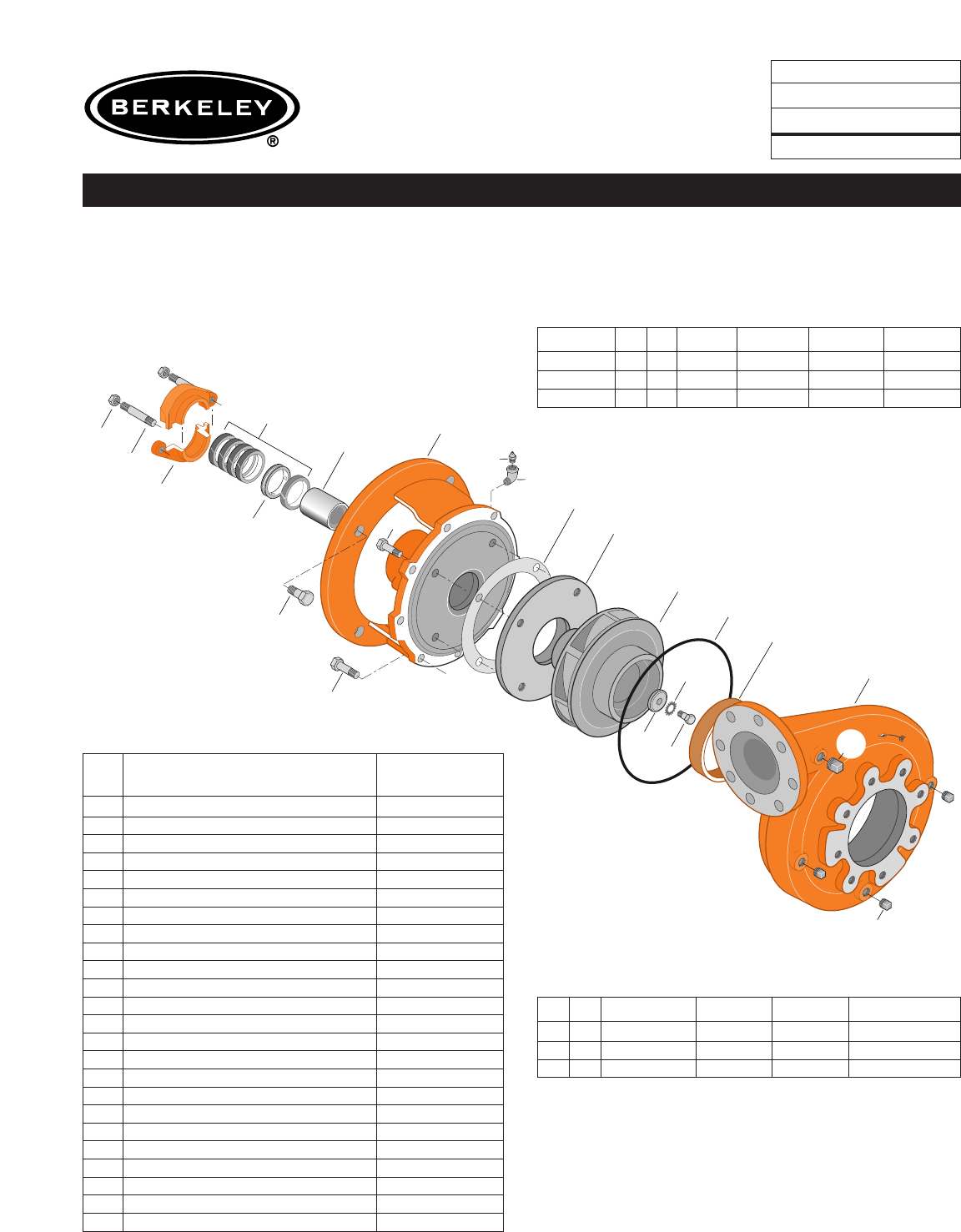
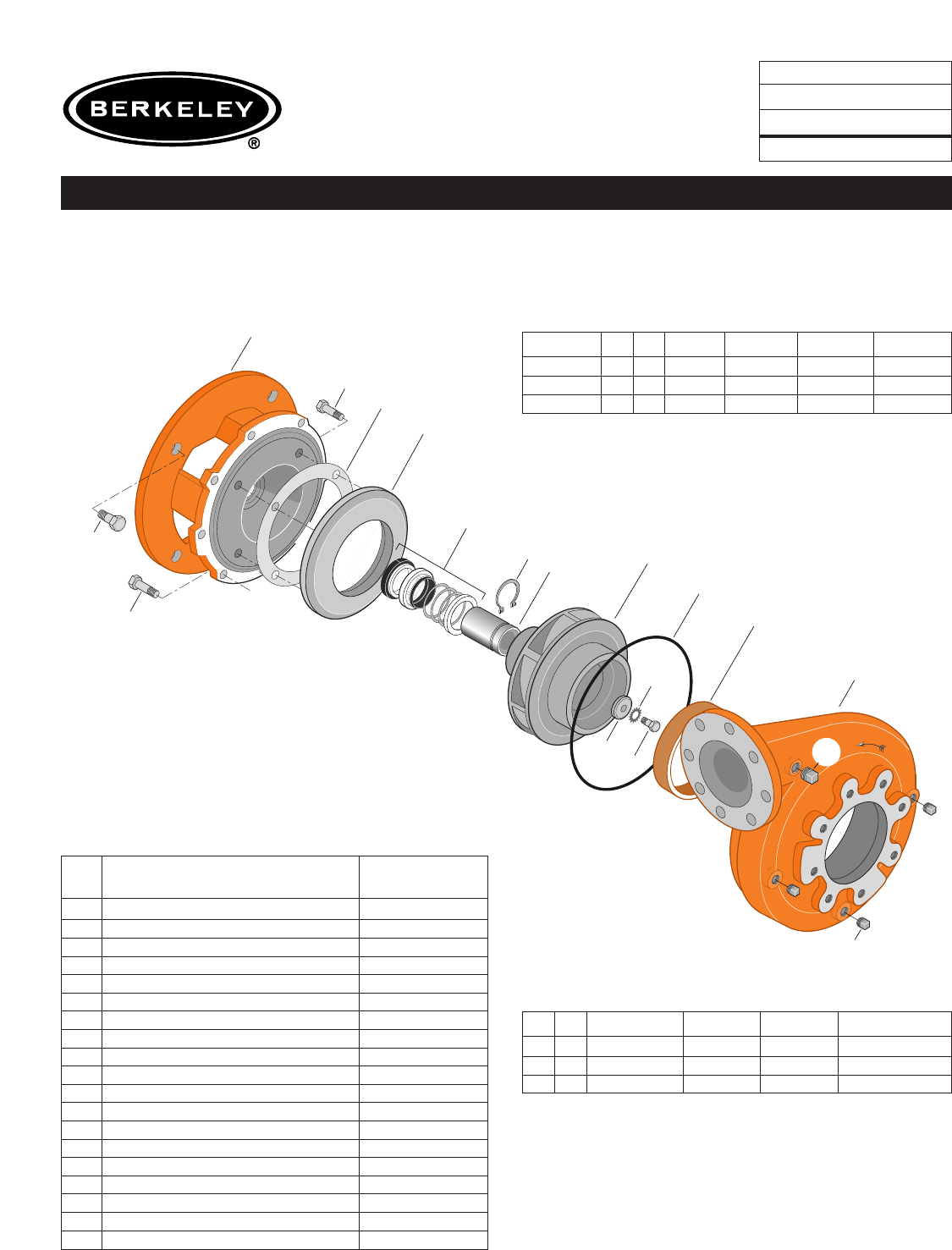
TYPE ‘‘B’’ SINGLE STAGE
CENTRIFUGAL PUMP
Electric Motor Drive
Section CC
Page 260.1
Date January 1, 2004
Supersedes 6/1/95
CAST IRON IMPELLER B4EPBM
Flanged Case Packing Construction
NOTE: For an explanation of the tabulated material
found on this page and for impeller key location, refer to
Supplement A located at the beginning of this section.
Form No. S4855BK
Item
No. Part Description Part Number
1Case, Volute H01939
2Impeller See Table I
7Ring, Wearing S32745
13 Rings, Packing (Set of 4) S13435
14 Sleeve, Shaft S05149
17 Gland, Packing B82470
26 Screw, Impeller 1/2 - 13 x 1-3/4” S23625
29 Ring, Lantern S19200
32 Key, 1/4 x 2-1/4” (See Note) S23677
69 Washer, Impeller S18117
71 Bracket See Table II
73 Gasket, Balance Ring S09943
115 Ring, Balance L03649
119 O-Ring S13760
800A Capscrew, 1/2 - 13 x 1-1/4” (8 Req.) S26914
800B Capscrew, 5/8 - 11 x 1-1/2” (4 Req.) S26999
800C Capscrew, 3/8 - 16 x 1” (4 Req.) S26826
801 Stud, 3/8 - 16 x 2-1/2” (2 Req.) S04438
802 Nut, Hex 3/8 - 16 (2 Req.) S23343
805 Washer, Lock S23038
810A Plug, Pipe 1/4 NPT (3 Req.) S23715
810B Plug, Pipe 1/2 NPT (2 Req.) S23717
811 Fitting, Grease S23700
812 Elbow, Street S25421
TABLE I
B/M No. HP PH RPM ‘‘U’’ Dim. Imp. Dia. Imp. No.
B58786 40 3 3600 1-1/4” 7.18” L06131
B58787 50 3 3600 1-1/4” 7.75” L06132
B58788 60 3 3600 1-1/4” 8.18” L06133
TABLE II
HP PH Bracket No. ‘‘AK’’ Fit ‘‘U’’ Dim. Motor Frame
40 3 L03497 12-1/2” 1-1/4” 286JP
50 3 L03497 12-1/2” 1-1/4” 324JP
60 3 L03497 12-1/2” 1-1/4” 326JP
1762 0495
1
2
805
26
69
119
7
810A
810B
17
801
802 14
29 811 115
73
800A
800B
800C
71
13
See Supplement B
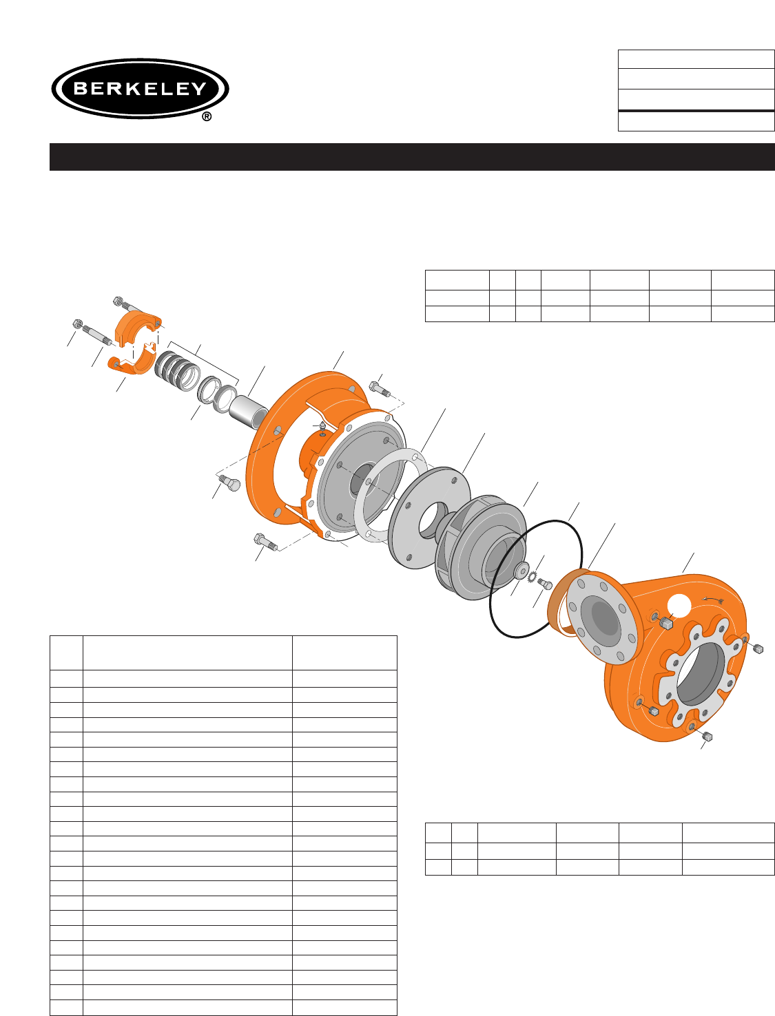
TYPE ‘‘B’’ SINGLE STAGE
CENTRIFUGAL PUMP
Electric Motor Drive
Section CC
Page 260.2
Date January 1, 2004
Supersedes 6/1/95
CAST IRON IMPELLER B4EPBM
Flanged Case Packing Construction
NOTE: For an explanation of the tabulated material
found on this page and for impeller key location, refer to
Supplement A located at the beginning of this section.
Form No. S4855BK
Item
No. Part Description Part Number
1Case, Volute H01939
2Impeller See Table I
7Ring, Wearing S32745
13 Rings, Packing (Set of 4) S13437
14 Sleeve, Shaft S07073
17 Gland, Packing B82471
26 Screw, Impeller 1/2 - 13 x 1-1/2” S23623
29 Ring, Lantern S19198
32 Key, 3/8 x 2-1/4” (See Note) S23940
69 Washer, Impeller S18801
71 Bracket See Table II
73 Gasket, Balance Ring S09943
115 Ring, Balance L03837
119 O-Ring S13760
800A Capscrew, 1/2 - 13 x 1-1/4” (8 Req.) S26914
800B Capscrew, 5/8 - 11 x 1-1/2” (4 Req.) S26999
800C Capscrew, 3/8 - 16 x 1” (4 Req.) S26826
801 Stud, 3/8 - 16 x 2-1/2” (2 Req.) S04438
802 Nut, Hex 3/8 - 16 (2 Req.) S23343
805 Washer, Lock S23038
810A Plug, Pipe 1/4 NPT (3 Req.) S23715
810B Plug, Pipe 1/2 NPT (2 Req.) S23717
811 Fitting, Grease S23700
TABLE I
B/M No. HP PH RPM ‘‘U’’ Dim. Imp. Dia. Imp. No.
B58789 75 3 3600 1-5/8” 8.75” L06134
B58790 100 3 3600 1-5/8” 9.62” L06135
TABLE II
HP PH Bracket No. ‘‘AK’’ Fit ‘‘U’’ Dim. Motor Frame
75 3 L05610 12-1/2” 1-5/8” 364JP
100 3 L05610 12-1/2” 1-5/8” 365JP
1763 0495
1
2
119
7
810A
810B
17
801
802 14
29 811 115
73
800A
800B
800C
71
24
40
13
See Supplement B
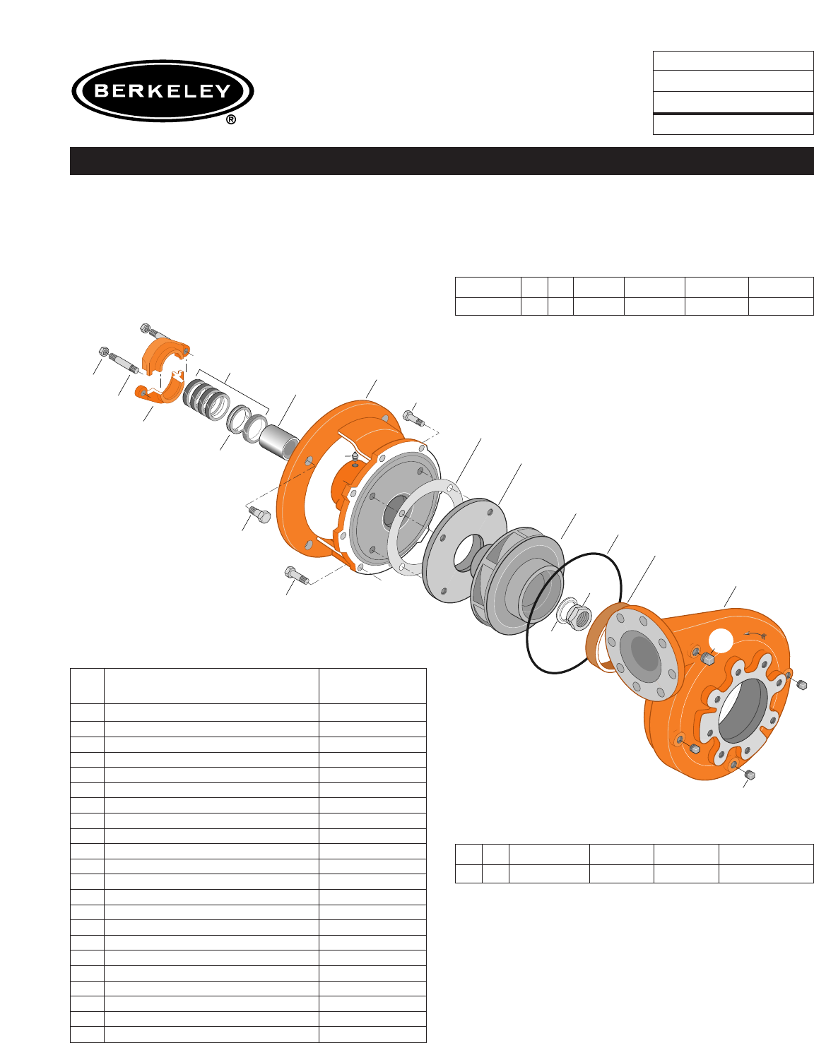
TYPE ‘‘B’’ SINGLE STAGE
CENTRIFUGAL PUMP
Electric Motor Drive
Section CC
Page 260.3
Date January 1, 2004
Supersedes 6/1/95
CAST IRON IMPELLER B4EPBM
Flanged Case Packing Construction
NOTE: For an explanation of the tabulated material
found on this page and for impeller key location, refer to
Supplement A located at the beginning of this section.
Form No. S4855BK
Item
No. Part Description Part Number
1Case, Volute H01939
2Impeller See Table I
7Ring, Wearing S32745
13 Rings, Packing (Set of 4) S13437
14 Sleeve, Shaft S07073
17 Gland, Packing B82471
24 Nut, Impeller S17955
29 Ring, Lantern S19198
32 Key, 3/8 x 2-1/4” (See Note) S23940
40 Deflector S17956
71 Bracket See Table II
73 Gasket, Balance Ring S09943
115 Ring, Balance L03837
119 O-Ring S13760
800A Capscrew, 1/2 - 13 x 1-1/4” (8 Req.) S26914
800B Capscrew, 5/8 - 11 x 1-1/2” (4 Req.) S26999
800C Capscrew, 3/8 - 16 x 7/8” (4 Req.) S26825
801 Stud, 3/8 - 16 x 2-1/2” (2 Req.) S04438
802 Nut, Hex 3/8 - 16 (2 Req.) S23343
810A Plug, Pipe 1/4 NPT (3 Req.) S23715
810B Plug, Pipe 1/2 NPT (2 Req.) S23717
811 Fitting, Grease S23700
TABLE I
B/M No. HP PH RPM ‘‘U’’ Dim. Imp. Dia. Imp. No.
B58791 125 3 3600 1-5/8” 10.44” L05889
TABLE II
HP PH Bracket No. ‘‘AK’’ Fit ‘‘U’’ Dim. Motor Frame
125 3 L05610 12-1/2” 1-5/8” 404TC

1678 0295
800A
71
89
115
73
T
r
u
a
r
c
815
1
2
805
26
69
119
7
800B
800C
14
810A
810B
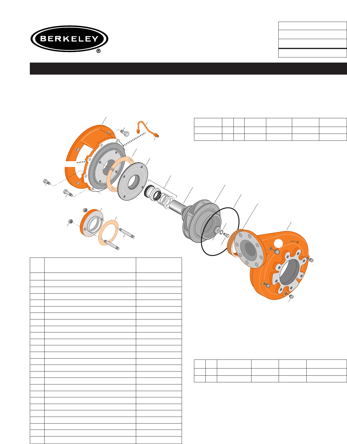
TYPE ‘‘B’’ SINGLE STAGE
CENTRIFUGAL PUMP
Electric Motor Drive
Section CC
Page 260.4
Date January 1, 2004
Supersedes 6/1/95
CAST IRON IMPELLER B4EPBMS
Flanged Case Mechanical Shaft Seal Construction
NOTE: For an explanation of the tabulated material
found on this page and for impeller key location, refer to
Supplement A located at the beginning of this section.
Form No. S4855BK
TABLE I
B/M No. HP PH RPM ‘‘U’’ Dim. Imp. Dia. Imp. No.
B58792 40 3 3600 1-1/4” 7.18” L06131
B58793 50 3 3600 1-1/4” 7.75” L06132
B58794 60 3 3600 1-1/4” 8.18” L06133
TABLE II
HP PH Bracket No. ‘‘AK’’ Fit ‘‘U’’ Dim. Motor Frame
40 3 L04628 12-1/2” 1-1/4” 286JM
50 3 L04628 12-1/2” 1-1/4” 324JM
60 3 L04628 12-1/2” 1-1/4” 326JM
Item
No. Part Description Part Number
1Case, Volute H01939
2Impeller See Table I
7Ring, Wearing S32745
14 Sleeve, Shaft S18869
26 Screw, Impeller 1/2 - 13 x 1-3/4” S23625
32 Key, 1/4 x 2-1/4” (See Note) S23677
69 Washer, Impeller S18117
71 Bracket See Table II
73 Gasket, Balance Ring S09943
89 Seal, Mechanical Shaft S32015
115 Ring, Balance L05263
119 O-Ring S13760
800A Capscrew, 1/2 - 13 x 1-1/4” (8 Req.) S26914
800B Capscrew, 5/8 - 11 x 1-1/2” (4 Req.) S26999
800C Capscrew, 3/8 - 16 x 3/4” (4 Req.) S26824
805 Washer, Lock S23038
810A Plug, Pipe 1/4 NPT (3 Req.) S23715
810B Plug, Pipe 1/2 NPT (2 Req.) S23717
815 Ring, Retaining S16767
1679 0295
800A
800B
800C
802
801
11
73B
820
71
822
89
115
73A
Seal Flush Line
Shown twice scale.
DETAIL- A
DETAIL- A
2
1
805
26
69
119
7
14
810A
810B
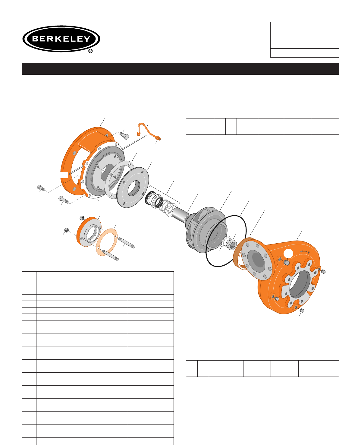
TYPE ‘‘B’’ SINGLE STAGE
CENTRIFUGAL PUMP
Electric Motor Drive
Section CC
Page 260.5
Date January 1, 2004
Supersedes 6/1/95
CAST IRON IMPELLER B4EPBMS
Flanged Case Mechanical Shaft Seal Construction
NOTE: For an explanation of the tabulated material
found on this page and for impeller key location, refer to
Supplement A located at the beginning of this section.
Form No. S4855BK
TABLE I
B/M No. HP PH RPM ‘‘U’’ Dim. Imp. Dia. Imp. No.
B62031 75 3 3600 1-5/8” 8.75” L06134
B61804 100 3 3600 1-5/8” 9.62” L06135
TABLE II
HP PH Bracket No. ‘‘AK’’ Fit ‘‘U’’ Dim. Motor Frame
75 3 L06315 12-1/2” 1-5/8” 364JP
100 3 L06315 12-1/2” 1-5/8” 365JP
Item
No. Part Description Part Number
1Case, Volute H01939
2Impeller See Table I
7Ring, Wearing S13061
11 Retainer, Mechanical Shaft Seal S15377
14 Sleeve, Shaft S07073
26 Screw, Impeller 1/2 - 13 x 1-1/2” S23623
32 Key, 3/8 x 2” (75 HP) (See Note) S23939
32 Key, 3/8 x 2-1/4” (100 HP) (See Note) S23940
69 Washer, Impeller S18801
71 Bracket See Table II
73A Gasket, Balance Ring S09943
73B Gasket, Seal Retainer S15078
89 Seal, Mechanical Shaft S32016
115 Ring, Balance L03837
119 O-Ring S13760
800A Capscrew, 1/2 - 13 x 1-1/4” (8 Req.) S26914
800B Capscrew, 5/8 - 11 x 1-3/4” (4 Req.) S27001
800C Capscrew, 3/8 - 16 x 1” (4 Req.) S26826
801 Stud, 3/8 - 16 x 2-1/2” (2 Req.) S04438
802 Nut, 3/8 x 16 (2 Req.) S23343
805 Washer, Lock S23038
810A Plug, Pipe 1/4 NPT (3 Req.) S23715
810B Plug, Pipe, 1/2 NPT (2 Req.) S23717
820 Connector, Comp. Fitting (2 Req.) S24013
822 Tubing, Copper S20677
•Plug, Pipe 1/8 NPT (At Seal Bore) S23714

1680 0295
800A
800B
800C
802
801
11
73B
820
71
822
89
115
73A
Seal Flush Line
Shown twice scale.
DETAIL- A
DETAIL- A
2
24
40
119
7
1
14
810A
810B
TYPE ‘‘B’’ SINGLE STAGE
CENTRIFUGAL PUMP
Electric Motor Drive
Section CC
Page 260.6
Date January 1, 2004
Supersedes 6/1/95
CAST IRON IMPELLER B4EPBMS
Flanged Case Mechanical Shaft Seal Construction
NOTE: For an explanation of the tabulated material
found on this page and for impeller key location, refer to
Supplement A located at the beginning of this section.
Form No. S4855BK
TABLE I
B/M No. HP PH RPM ‘‘U’’ Dim. Imp. Dia. Imp. No.
B62032 125 3 3600 1-5/8” 10.44” L05889
TABLE II
HP PH Bracket No. ‘‘AK’’ Fit ‘‘U’’ Dim. Motor Frame
125 3 L06315 12-1/2” 1-5/8” 404TC
Item
No. Part Description Part Number
1Case, Volute H01939
2Impeller See Table I
7Ring, Wearing S32745
11 Retainer, Mechanical Shaft Seal S15377
14 Sleeve, Shaft S07073
24 Locknut, Impeller S17955
32 Key, 3/8 x 2-1/4” (See Note) S23940
40 Deflector S17956
71 Bracket See Table II
73A Gasket, Balance Ring S09943
73B Gasket, Seal Retainer S15078
89 Seal, Mechanical Shaft S32016
115 Ring, Balance L03837
119 O-Ring S13760
800A Capscrew, 1/2 - 13 x 1-1/4” (8 Req.) S26914
800B Capscrew, 5/8 - 11 x 1-3/4” (4 Req.) S27001
800C Capscrew, 3/8 - 16 x 7/8” (4 Req.) S26825
801 Stud, 3/8 - 16 x 2-1/2” (2 Req.) S04438
802 Nut, 3/8 - 16 (2 Req.) S23343
810A Plug, Pipe 1/4 NPT (3 Req.) S23715
810B Plug, Pipe 1/2 NPT (2 Req.) S23717
820 Connector, Comp. Fitting (2 Req.) S24013
822 Tubing, Copper S20677
•Plug, Pipe 1/8 NPT (At Seal Bore) S23714
1678 0295
800A
71
89
115
73
T
r
u
a
r
c
815
1
2
805
26
69
119
7
800B
800C
14
810A
810B
TYPE ‘‘B’’ SINGLE STAGE
CENTRIFUGAL PUMP
Electric Motor Drive
Section CC
Page 260.7
Date January 1, 2004
Supersedes/New
BRONZE IMPELLER B4EPBMS
Flanged Case Mechanical Shaft Seal Construction
NOTE: For an explanation of the tabulated material
found on this page and for impeller key location, refer to
Supplement A located at the beginning of this section.
Form No. S4855BK
TABLE I
B/M No. HP PH RPM ‘‘U’’ Dim. Imp. Dia. Imp. No.
B76769 40 3 3600 1-1/4” 7.18” M11559
B76770 50 3 3600 1-1/4” 7.75” M11560
B76425 60 3 3600 1-1/4” 8.18” L08540
TABLE II
HP PH Bracket No. ‘‘AK’’ Fit ‘‘U’’ Dim. Motor Frame
40 3 L04628 12-1/2” 1-1/4” 286JM
50 3 L04628 12-1/2” 1-1/4” 324JM
60 3 L04628 12-1/2” 1-1/4” 326JM
Item
No. Part Description Part Number
1Case, Volute H01939
2Impeller See Table I
7Ring, Wearing S32745
14 Sleeve, Shaft S18869
26 Screw, Impeller 1/2 - 13 x 1-3/4” S23625
32 Key, 1/4 x 2-1/4” (See Note) S23677
69 Washer, Impeller S18117
71 Bracket See Table II
73 Gasket, Balance Ring S09943
89 Seal, Mechanical Shaft S32015
115 Ring, Balance L05263
119 O-Ring S13760
800A Capscrew, 1/2 - 13 x 1-1/4” (8 Req.) S26914
800B Capscrew, 5/8 - 11 x 1-1/2” (4 Req.) S26999
800C Capscrew, 3/8 - 16 x 3/4” (4 Req.) S26824
805 Washer, Lock S23038
810A Plug, Pipe 1/4 NPT (3 Req.) S23715
810B Plug, Pipe 1/2 NPT (2 Req.) S23717
815 Ring, Retaining S16767

1679 0295
800A
800B
800C
802
801
11
73B
820
71
822
89
115
73A
Seal Flush Line
Shown twice scale.
DETAIL- A
DETAIL- A
2
1
805
26
69
119
7
14
810A
810B
TYPE ‘‘B’’ SINGLE STAGE
CENTRIFUGAL PUMP
Electric Motor Drive
Section CC
Page 260.8
Date January 1, 2004
Supersedes/New
BRONZE IMPELLER B4EPBMS
Flanged Case Mechanical Shaft Seal Construction
NOTE: For an explanation of the tabulated material
found on this page and for impeller key location, refer to
Supplement A located at the beginning of this section.
Form No. S4855BK
TABLE I
B/M No. HP PH RPM ‘‘U’’ Dim. Imp. Dia. Imp. No.
B76771 75 3 3600 1-5/8” 8.75” L08529
B76772 100 3 3600 1-5/8” 9.62” M11561
TABLE II
HP PH Bracket No. ‘‘AK’’ Fit ‘‘U’’ Dim. Motor Frame
75 3 L06315 12-1/2” 1-5/8” 364JP
100 3 L06315 12-1/2” 1-5/8” 365JP
Item
No. Part Description Part Number
1Case, Volute H01939
2Impeller See Table I
7Ring, Wearing S13061
11 Retainer, Mechanical Shaft Seal S15377
14 Sleeve, Shaft S07073
26 Screw, Impeller 1/2 - 13 x 1-1/2” S23623
32 Key, 3/8 x 2” (75 HP) (See Note) S23939
32 Key, 3/8 x 2-1/4” (100 HP) (See Note) S23940
69 Washer, Impeller S18801
71 Bracket See Table II
73A Gasket, Balance Ring S09943
73B Gasket, Seal Retainer S15078
89 Seal, Mechanical Shaft S32016
115 Ring, Balance L03837
119 O-Ring S13760
800A Capscrew, 1/2 - 13 x 1-1/4” (8 Req.) S26914
800B Capscrew, 5/8 - 11 x 1-3/4” (4 Req.) S27001
800C Capscrew, 3/8 - 16 x 1” (4 Req.) S26826
801 Stud, 3/8 - 16 x 2-1/2” (2 Req.) S04438
802 Nut, 3/8 x 16 (2 Req.) S23343
805 Washer, Lock S23038
810A Plug, Pipe 1/4 NPT (3 Req.) S23715
810B Plug, Pipe, 1/2 NPT (2 Req.) S23717
820 Connector, Comp. Fitting (2 Req.) S24013
822 Tubing, Copper S20677
•Plug, Pipe 1/8 NPT (At Seal Bore) S23714
1680 0295
800A
800B
800C
802
801
11
73B
820
71
822
89
115
73A
Seal Flush Line
Shown twice scale.
DETAIL- A
DETAIL- A
2
24
40
119
7
1
14
810A
810B
TYPE ‘‘B’’ SINGLE STAGE
CENTRIFUGAL PUMP
Electric Motor Drive
Section CC
Page 260.9
Date January 1, 2004
Supersedes/New
BRONZE IMPELLER B4EPBMS
Flanged Case Mechanical Shaft Seal Construction
NOTE: For an explanation of the tabulated material
found on this page and for impeller key location, refer to
Supplement A located at the beginning of this section.
Form No. S4855BK
TABLE I
B/M No. HP PH RPM ‘‘U’’ Dim. Imp. Dia. Imp. No.
B76773 125 3 3600 1-5/8” 10.44” M11562
TABLE II
HP PH Bracket No. ‘‘AK’’ Fit ‘‘U’’ Dim. Motor Frame
125 3 L06315 12-1/2” 1-5/8” 404TC
Item
No. Part Description Part Number
1Case, Volute H01939
2Impeller See Table I
7Ring, Wearing S32745
11 Retainer, Mechanical Shaft Seal S15377
14 Sleeve, Shaft S07073
24 Locknut, Impeller S17955
32 Key, 3/8 x 2-1/4” (See Note) S23940
40 Deflector S17956
71 Bracket See Table II
73A Gasket, Balance Ring S09943
73B Gasket, Seal Retainer S15078
89 Seal, Mechanical Shaft S32016
115 Ring, Balance L03837
119 O-Ring S13760
800A Capscrew, 1/2 - 13 x 1-1/4” (8 Req.) S26914
800B Capscrew, 5/8 - 11 x 1-3/4” (4 Req.) S27001
800C Capscrew, 3/8 - 16 x 7/8” (4 Req.) S26825
801 Stud, 3/8 - 16 x 2-1/2” (2 Req.) S04438
802 Nut, 3/8 - 16 (2 Req.) S23343
810A Plug, Pipe 1/4 NPT (3 Req.) S23715
810B Plug, Pipe 1/2 NPT (2 Req.) S23717
820 Connector, Comp. Fitting (2 Req.) S24013
822 Tubing, Copper S20677
•Plug, Pipe 1/8 NPT (At Seal Bore) S23714
