CheckIt_3Phase Duplex_IOM__Comp 552754 2 Alderon Three Phase Duplex Control Panel Installation Manual
552759 2 Alderon Three Phase Duplex Control Panel Installation Manual 552759_2_Alderon Three Phase Duplex Control Panel Installation Manual
552760 2 Alderon Three Phase Duplex Control Panel Installation Manual 552760_2_Alderon Three Phase Duplex Control Panel Installation Manual
552757 2 Alderon Three Phase Duplex Control Panel Installation Manual 552757_2_Alderon Three Phase Duplex Control Panel Installation Manual
552752 2 Alderon Three Phase Duplex Control Panel Installation Manual 552752_2_Alderon Three Phase Duplex Control Panel Installation Manual
552755 2 Alderon Three Phase Duplex Control Panel Installation Manual 552755_2_Alderon Three Phase Duplex Control Panel Installation Manual
: Pump 552754 2 Alderon Three Phase Duplex Control Panel Installation Manual 552754_2_Alderon Three Phase Duplex Control Panel Installation Manual pdf
Open the PDF directly: View PDF ![]() .
.
Page Count: 5

Check It Panel
Introduction
Before proceeding with the installation or operation of the control panel read all instructions thoroughly,
as well as comply with all Federal, State and Local Codes, Regulations and Practices. The control panel
must be installed by qualified personnel familiar with all applicable local electrical and mechanical codes.
Refer to the National Electrical Code (NFPA 70). Failure to properly install and test this product can result
in personal injury or equipment malfunction. All conduit connected to the panel must be sealed with
conduit sealant to prevent moisture or gases from entering the panel. NEMA 1 enclosures are for indoor
use only while NEMA 4X panel enclosures may be used indoor or outdoor. Refer to panel model name-
plate on inside of door for enclosure rating. Note: If options are ordered that affect the number of floats,
refer to the panel schematic for complete information.
Safety Guidelines
1. DO NOT USE WITH FLAMMABLE OR EXPLOSIVE FLUIDS SUCH AS GASOLINE, FUEL OIL, KEROSENE,
ETC. DO NOT USE IN EXPLOSIVE ATMOSPHERES. CONTROL PANEL SHOULD ONLY BE USED IN
WATER AND WASTEWATER APPLICATIONS THAT ARE NOT RATED AS A HAZARDOUS LOCATION.
2. DO NOT WORK ON THE CONTROL PANEL WITH LIVE VOLTAGE APPLIED TO THE CONTROL PANEL
WITH WET HANDS OR WHEN STANDING ON A WET SURFACE.
3. DISCONNECT ALL ELECTRICAL SERVICE BEFORE WORKING ON OR HANDLING THE CONTROL
PANEL
4. INCOMING VOLTAGE MUST MATCH THE CONTROL PANEL VOLTAGE. REFER TO THE PANEL SCHE-
MATIC FOR COMPLETE INFORMATION.
P/N Page 1 of 5
TM
Installation of the Control Panel:
-
1. Determine mounting location for the control panel. If splicing is required between the level
switches and the panel, we recommend an Alderon Junction box. CAUTION! Use conduit sealant and
waterproof wire nuts for connections. Make sure all connections are water tight.
2. Determine conduit entrance locations on control panel and install per local codes. Check sche-
matic and determine number of power sources required. Use conduit sealant on all conduits to prevent
moisture and gases from entering control panel.
3. Connect control/alarm and pump power conductors to the proper terminals. The schematic and
terminal blocks will be labeled for proper and terminal blocks will be labeled for proper connection.
4. Verify correct panel operation after installation of panel, power and level switches are complete.
Operation & Maintenance Manual - 3 Phase Duplex
Check It Panel
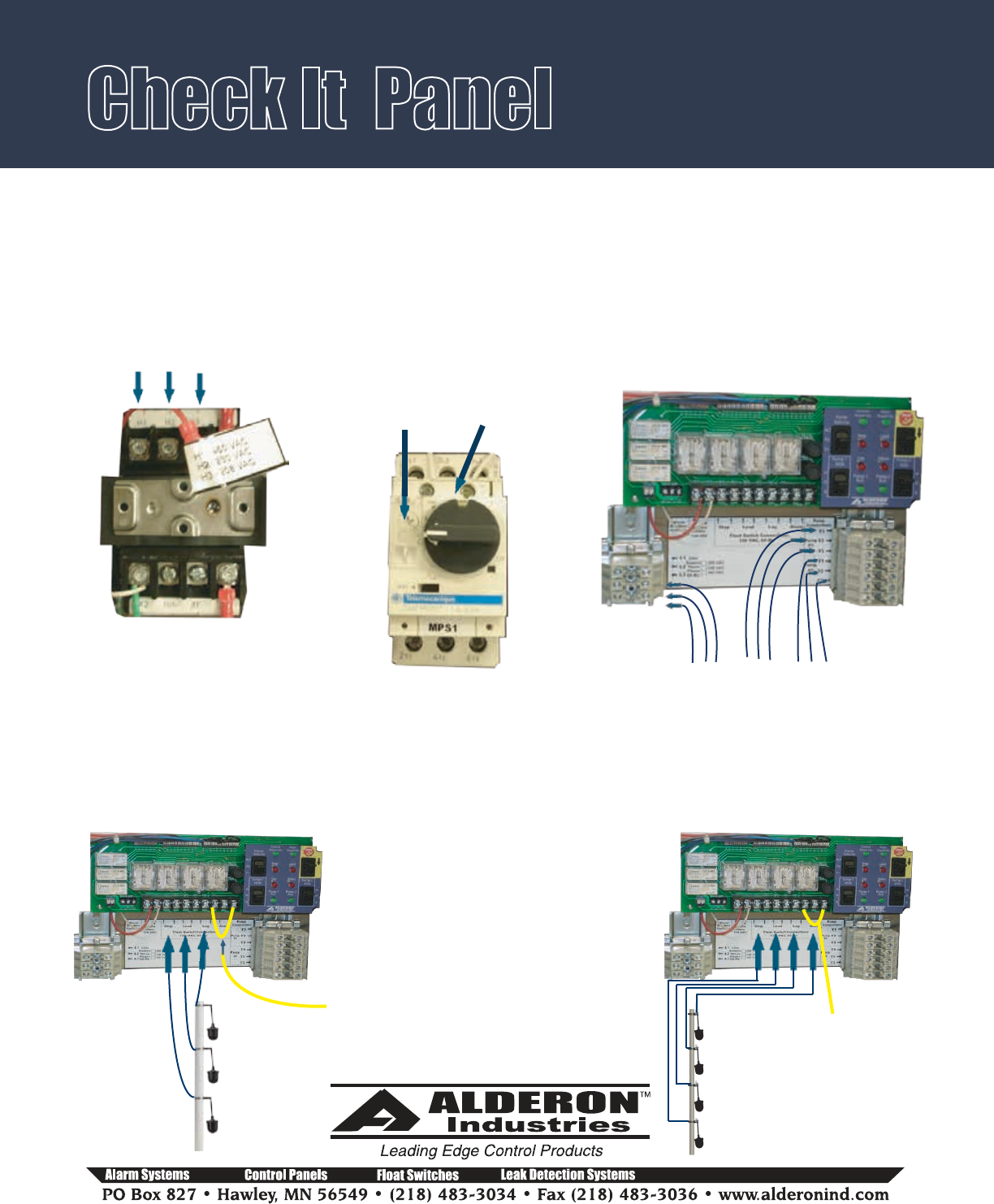
Field Wiring Connections:
Check It series control panels are multi voltage. Set the transformer voltage to match incoming power
voltage. Set the amperage on the motor protective switches to match the pump full load amps.
Pump Power Configurations
Mounting Level Switches:
Stop Float
Start Float
Lag/Alarm Float
Set transformer to match
incoming voltage.
460 230 208 0
Connect incoming power and connect
each pump.
P/N Page 2 of 5
TM
L3 L2 L1
Incoming
Power
Pump 1
Connection
T1 T2 T3
Pump 2
Connection
T1 T2 T3
Connecting 3 float switches
Float switches are most commonly used, but the Check It series control panels can be used with any dry
contact type level or pressure switch. Illustrations show float switches installed for pump down applications.
Reverse float order for Pump Up applications. Refer to float switch instructions for mounting of pipe clamp or
weighted floats.
Stop Float
Lead Float
Lag Float
Connecting 4 float switches
Alarm Float
Set amps
of each
overload
to match
pump
amps.
When panel
is ready for
operation,
place the
switch in the
on position.
Jumper wire
from terminal 6
to terminal 8
REMOVE -
Jumper wire
from terminal 6
to terminal 8.
Operation & Maintenance Manual - 3 Phase Duplex
Check It Panel
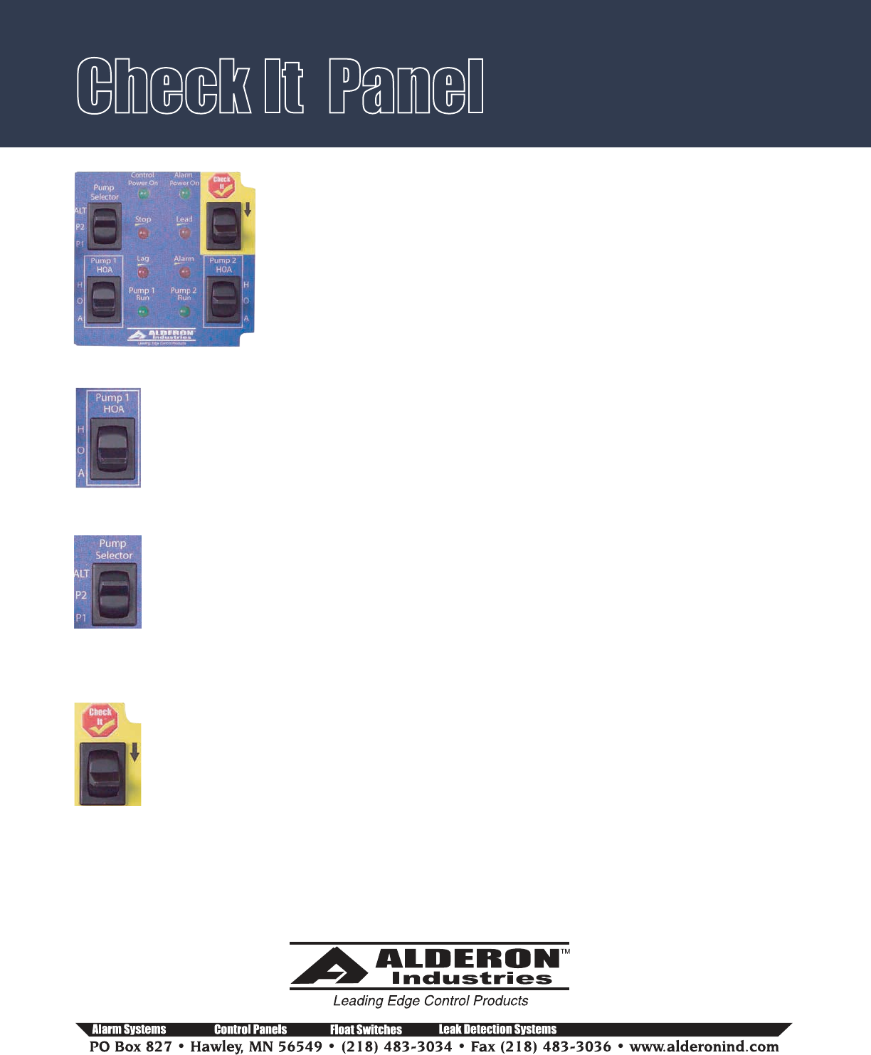
Circuit Board Command Center:
The control panel is equipped with a circuit board and control command
center. There are two “HOA” switches, a pump selector switch and a Check It
switch. Two green power “on” indicators provide visual indication for the
control and alarm fuses. Fuses must be replaced with 1 amp fast acting 5mm
x 20mm fuses. 4 red level indicators are provided for level indication of the
off, lead, lag and alarm switches.
HOA switch:
Placing the HOA switch in “H” (hand mode) will activate the pump. In the “O” (off) mode the
pump will not activate. Placing the switch in “A” (automatic) mode, will activate the pump
with the level switches. Place the switch in “A” mode when installation is complete and normal
operation is desired.
Pump selector switch:
Placing the switch in “ALT” will allow the panel to automatically alternate the pumps on
successive cycles. If a pump needs to be taken out of service, place the switch to the pump
that will remain in service. I.E. if pump 2 is out of service, place the switch to “P1” so the panel
will activate pump 1 on each cycle. Note: If the level reaches the lag/alarm or alarm switch
level the alarm will activate. For applications where alternation is not desired and a lag pump
operation is required, consult factory for further information. When a pump is selected with
the pump selector switch only that pump will activate (simplex mode).
Check It switch:
Use the Check It switch to verify panel operation and float status. To check panel operation
place the pump selector switch to “Alt” and the HOA switches to “A”. Press and hold the Check
It switch – one pump should activate. De-Press the Check It switch and Re-Press again and the
other pump should activate. The panel will alternate the pumps each time the Check It switch
is pressed.
Use the Check It switch to verify float status. In normal operation the float status LED’s activate when the
level switch “closes”. If the floats are activated out of sequence (I.E., “off” float is not activated but the
“lead” float is activated) the LED for the “lead” switch will not illuminate. Use the Check It switch to deter-
mine exact status of each float. When the Check It switch is pressed and held, the circuit will automatically
give true indication of which level switches are “closed” or “opened”. You can perform this test with the
“HOA” switch in either the “O” (off) or “A” (auto) modes.
P/N Page 3 of 5
TM
Operation & Maintenance Manual - 3 Phase Duplex
Check It Panel
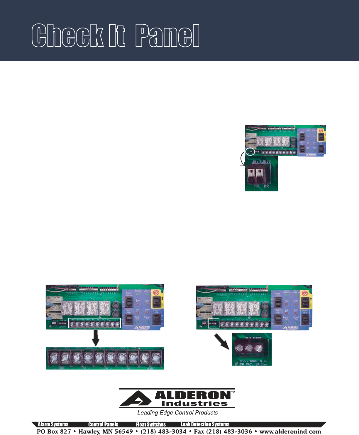
Alarm Mode Configurations:
All “e” (economy) series control panels will only have a combination “test-normal-silence” switch where
automatic alarm reset is the only alarm configuration. When the panel goes into alarm, press the switch to
“silence” and the buzzer will turn off but the alarm indicator will remain on until the lag/alarm or alarm
level switch deactivates and automatically resets the alarm system.
All other Check It series control panels employ separate “test” and
“silence” switches. These panels can be field modified to have a “manual”
alarm reset. Refer to figure for placement of an 18 AWG jumper wire to
convert the panel from automatic reset to MANUAL reset. In the Manual
Reset mode and when the panel goes into alarm, the panel will remain in
alarm even if the alarm level switch is “opened” until the “silence” switch
is activated. This feature allows alarms to be manually acknowledged
before the alarm is cleared. In the event of a power failure, the alarm is
also cleared.
Use 18 AWG wire approximately 4” long. Strip off ¼” outer insulation. Insert jumper wire into the 2 posi-
tion wire port (one wire per port). To remove jumper wire, press small screw driver or pointed object onto
the “white” port block and remove wire as the wire is held in place by a spring cage terminal device.
P/N Page 4 of 5
TM
Circuit Board Terminal Blocks:
The Check It series control panel uses two terminal blocks. A 10 position main terminal block is for power
and level switch connections. A separate 3 position terminal block are for dry auxiliary contacts. A 5 amp,
120 VAC max load can be applied to the auxiliary terminals. The auxiliary contacts are Form C, Single Pole,
Double Throw. (Common, Normally Open, Normally Closed). Contacts change state when in alarm condi-
tion.
10 position terminal block Auxiliary Contact terminal block
WARNING! When using the manual alarm reset feature you
must use a four float system. If you’re using a 3 float system, add a fourth float and remove the yellow jumper
wire between the lag and alarm terminals to avoid dry pumping.
Operation & Maintenance Manual - 3 Phase Duplex
Check It Panel
P/N Page 5 of 5
TM
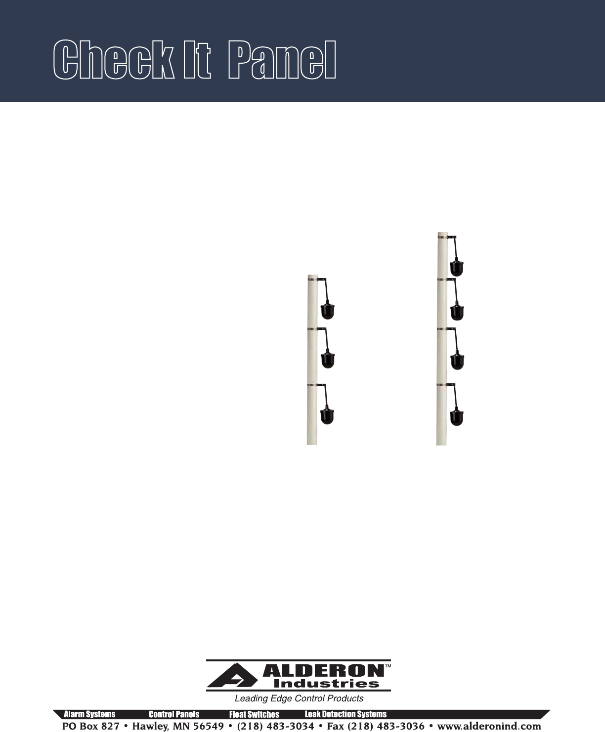
-
Float switches are most commonly used, but the
Check It series control panels can be used with any
dry contact type level or pressure switch. Illustra-
tions show float switches and installed for pump
down applications. Reverse float order for Pump Up
applications. Refer to float switch instuctions for
mounting of pipe clamp or weighted floats.
Mounting Level Switches:
Fig. #A
3 float configuration
Fig. #B
4 float configuration
Stop Float
Lead Pump
Start Float
Lag Pump Start
& Alarm Float
Stop Float
Lead Pump
Start Float
Lag Pump
Start Float
Alarm Float
Description of Operation.
3 Float:
4 Float:
With both “HOA” switches in “Auto” and the
pump selector switch in “ALT”: On water rise, the
“off” float will close and when the level closes the
“lead” float, pump 1 will start and pump down to
the “off” float. The panel will alternate so on the
next cycle pump 2 will activate. If the level
reaches the “lag” float, both pumps and the
alarm will activate and pump down to the “off”
float. Alarm turns off at the “off” level. For a
pump up application the floats are reversed (see
float configurations Fig. #A.
With both “HOA” switches in “Auto” and the
pump selector switch in “ALT”: On water rise, the
“off” float will close and when the level closes the
“lead” float, pump 1 will start and pump down to
the “off” float. The panel will alternate so on the
next cycle pump 2 will activate. If the level
reaches the “lag” float, both pumps will activate
and pump down to the “off” float. If the reaches
the “alarm” float the alarm will activate. Alarm
turns off when the alarm float is “off”. For a pump
up application the floats are reversed (see float
configurations Fig. #B.
Operation & Maintenance Manual - 3 Phase Duplex
