FM Section 84532 5 Berkeley B58085 Repair Parts I
: Pump 84532 5 Berkeley B58085 Repair Parts I 84532_5_Berkeley B58085 Repair Parts I pdf
Open the PDF directly: View PDF ![]() .
.
Page Count: 6
1
810
800A
71
26A (7/8 U)
26B (1-1/4 U)
69A (7/8 U)
69B (1-1/4 U)
73
2
14A (7/8 U)
14B (1-1/4 U)
13B (1-1/4 U)
13A (7/8 U)
17A (7/8 U)
17B (1-1/4 U)
1719 0495
800B (7/8 U)
800C (1-1/4U)
801A (7/8 U)
801B (1-1/4 U)
802
805
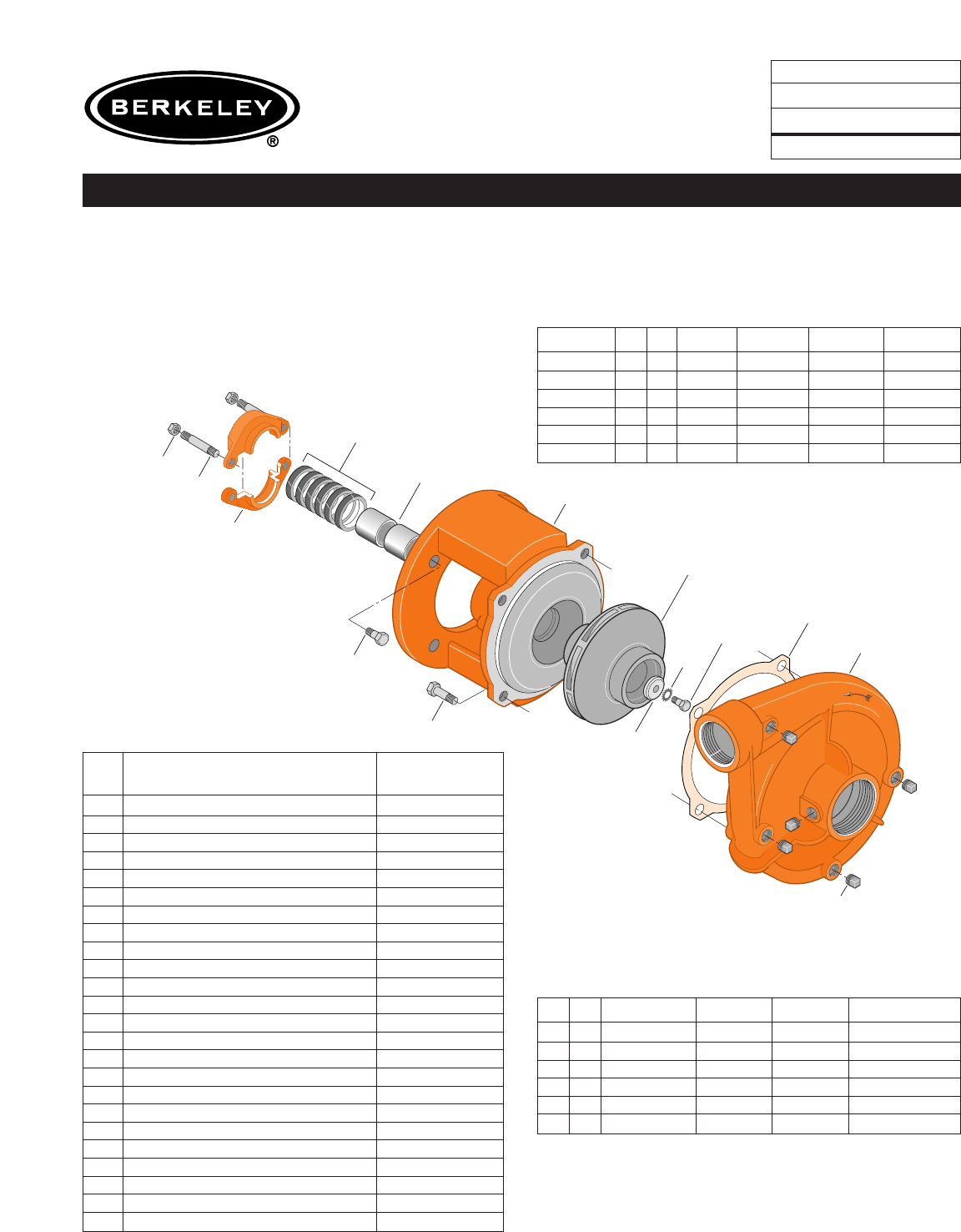
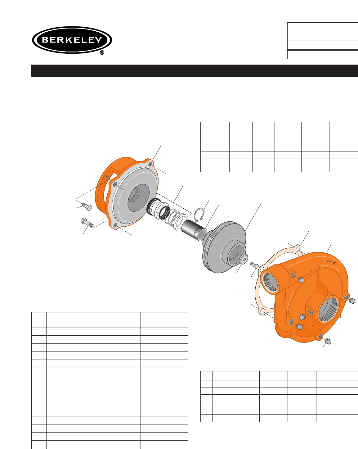
TYPE ‘‘B’’ SINGLE STAGE
CENTRIFUGAL PUMP
Electric Motor Drive
Section CC
Page 30.1
Date January 1, 2004
Supersedes 6/1/95
CAST IRON IMPELLER B1-1/2TPM
Threaded Case (NPT) Packing Construction
NOTE: For an explanation of the tabulated material
found on this page and for impeller key location, refer to
Supplement A located at the beginning of this section.
Form No. S4855BK
Item
No. Part Description Part Number
1Case, Volute L01018
2Impeller See Table I
13A Rings, Packing (Set of 6) S13469
13B Rings, Packing (Set of 6) S13470
14A Sleeve, Shaft (2 Req.) S00619
14B Sleeve, Shaft S05149
17A Gland, Packing B82469
17B Gland, Packing B82470
26A Screw, Impeller, 3/8 - 16 x 1” S23566
26B Screw, Impeller 1/2 - 13 x 1” S23619
32A Key, 3/16 x 1-1/4” (See Note) S34383
32B Key, 1/4 x 2-1/4” (See Note) S23677
69A Washer, Impeller S16239
69B Washer, Impeller S06317
71 Bracket See Table II
73 Gasket, Volute S04757
800A Capscrew, 1/2 - 13 x 1” (4 Req.) S26912
800B Capscrew, 1/2 - 13 x 1” (8 Req.) S26912
800C Capscrew, 3/8 - 16 x 7/8” (4 Req.) S26825
801A Stud, 3/8 - 16 x 4” (2 Req.) S08303
801B Stud, 3/8 - 16 x 3-1/2” (2 Req.) S04441
802 Nut, Hex 3/8 - 16 (2 Req.) S23343
805 Washer, Lock S23038
810 Plug, Pipe 1/4 NPT (5 Req.) S23715
TABLE I
B/M No. HP PH RPM ‘‘U’’ Dim. Imp. Dia. Imp. No.
B58143 51 3600 7/8” 5.50” M07637
B58144 53 3600 7/8” 5.50” M07637
B58145 7.5 1 3600 1-1/4” 6.00” S34238
B58146 7.5 3 3600 7/8” 6.00” M07638
B58147 10 1 3600 1-1/4” 6.56” S32401
B58148 10 3 3600 1-1/4” 6.56” S32401
TABLE II
HP PH Bracket No. ‘‘AK’’ Fit ‘‘U’’ Dim. Motor Frame
51 L01525 4-1/2” 7/8” 184JP
53 L01525 4-1/2” 7/8” 182JP
7.5 1 L01951 8-1/2” 1-1/4” 213JP
7.5 3 L01525 4-1/2” 7/8” 184JP
10 1 L01951 8-1/2” 1-1/4” 215JP
10 3 L01951 8-1/2” 1-1/4” 213JP
T
r
u
a
r
c
1
810
815
800A
800B
71
26
69
73
2
14
89
1479 0195
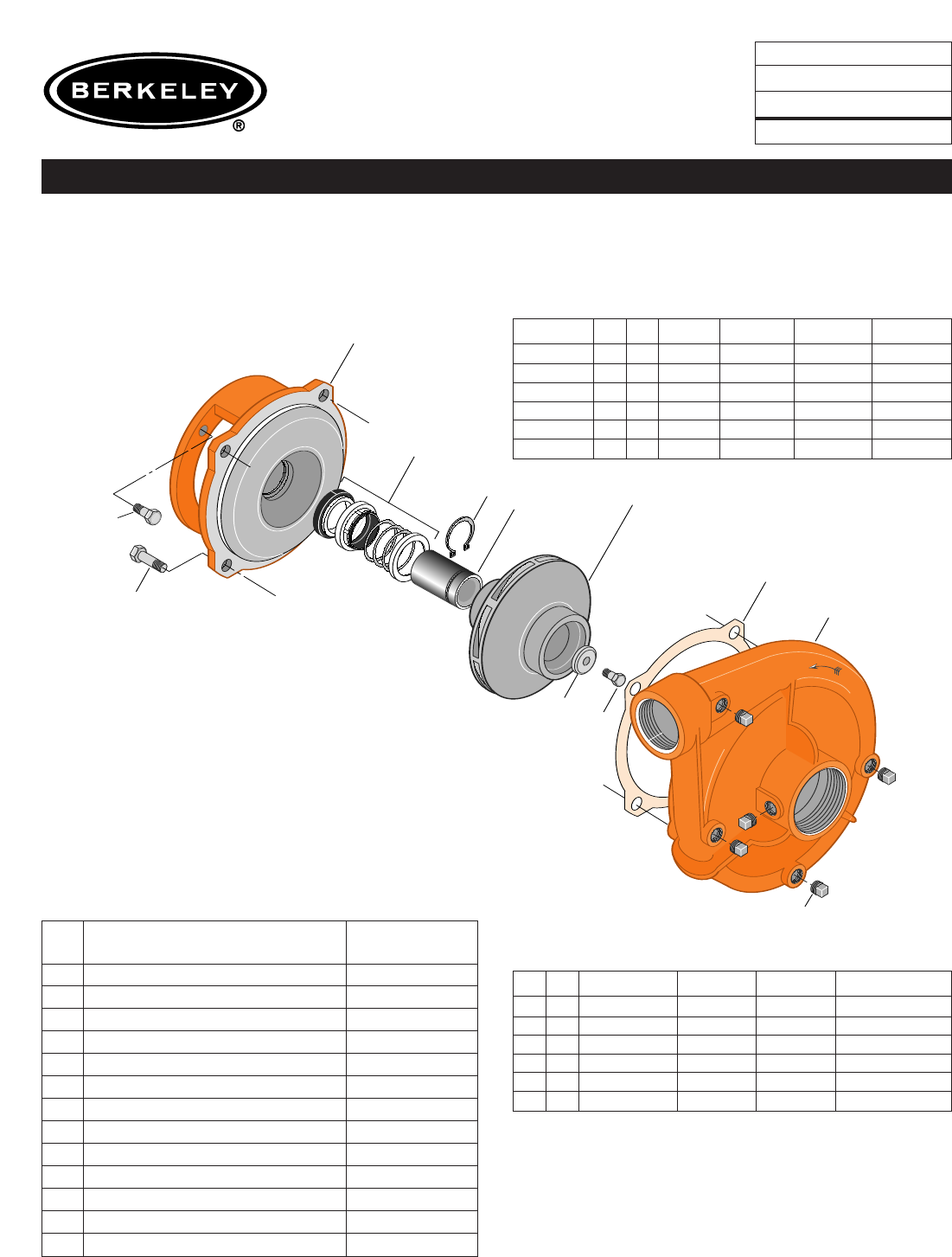
TYPE ‘‘B’’ SINGLE STAGE
CENTRIFUGAL PUMP
Electric Motor Drive
Section CC
Page 30.2
Date May 15, 2009
Supersedes 1/1/04
CAST IRON IMPELLER B1-1/2TPMS
Threaded Case (NPT) Mechanical Shaft Seal Construction
NOTE 1: For an explanation of the tabulated material
found on this page and for impeller key location, refer to
Supplement A located at the beginning of this section.
NOTE 2: Sleeve replacement kit available. Berkeley
part number B85681 includes the shaft sleeve, adhesive
compound and instruction sheet.
Form No. S4855BK
TABLE I
B/M No. HP PH RPM ‘‘U’’ Dim. Imp. Dia. Imp. No.
B58083 5 1 3600 7/8” 5.50” M07637
B58084 5 3 3600 7/8” 5.50” M07637
B58085 7.5 1 3600 7/8” 6.00” M07638
B58086 7.5 3 3600 7/8” 6.00” M07638
B58087 10 1 3600 7/8” 6.56” M07298
B58088 10 3 3600 7/8” 6.56” M07298
TABLE II
HP PH Bracket No. ‘‘AK’’ Fit ‘‘U’’ Dim. Motor Frame
5 1 L05329 4-1/2” 7/8” 184JM
5 3 L05329 4-1/2” 7/8” 182JM
7.5 1 L05328 8-1/2” 7/8” 213JM
7.5 3 L05329 4-1/2” 7/8” 184JM
10 1 L05328 8-1/2” 7/8” 215JM
10 3 L05328 8-1/2” 7/8” 213JM
Item
No. Part Description Part Number
1 Case, Volute L01018
2 Impeller See Table I
14 Sleeve, Shaft (See Note 2) S19310L
2 6 Screw, Impeller 3/8 - 16 x 1” S23566
32 Key, 3/16 x 1-1/4” (See Note 1) S34383
69 Washer, Impeller S16239
71 Bracket See Table II
73 Gasket, Volute S04757
89 Seal, Mechanical Shaft S32014
800A Capscrew, 1/2 - 13 x 1” (8 Req.) S26912
800B Capscrew, 3/8 - 16 x 1” (4 Req.) S26826
810 Plug, Pipe 1/4 NPT (5 Req.) S23715
815 Ring, Retaining S11207
1
810
800A
71
26A (7/8 U)
26B (1-1/4 U)
69A (7/8 U)
69B (1-1/4 U)
73
2
14A (7/8 U)
14B (1-1/4 U)
13B (1-1/4 U)
13A (7/8 U)
17A (7/8 U)
17B (1-1/4 U)
1719 0495
800B (7/8 U)
800C (1-1/4U)
801A (7/8 U)
801B (1-1/4 U)
802
805
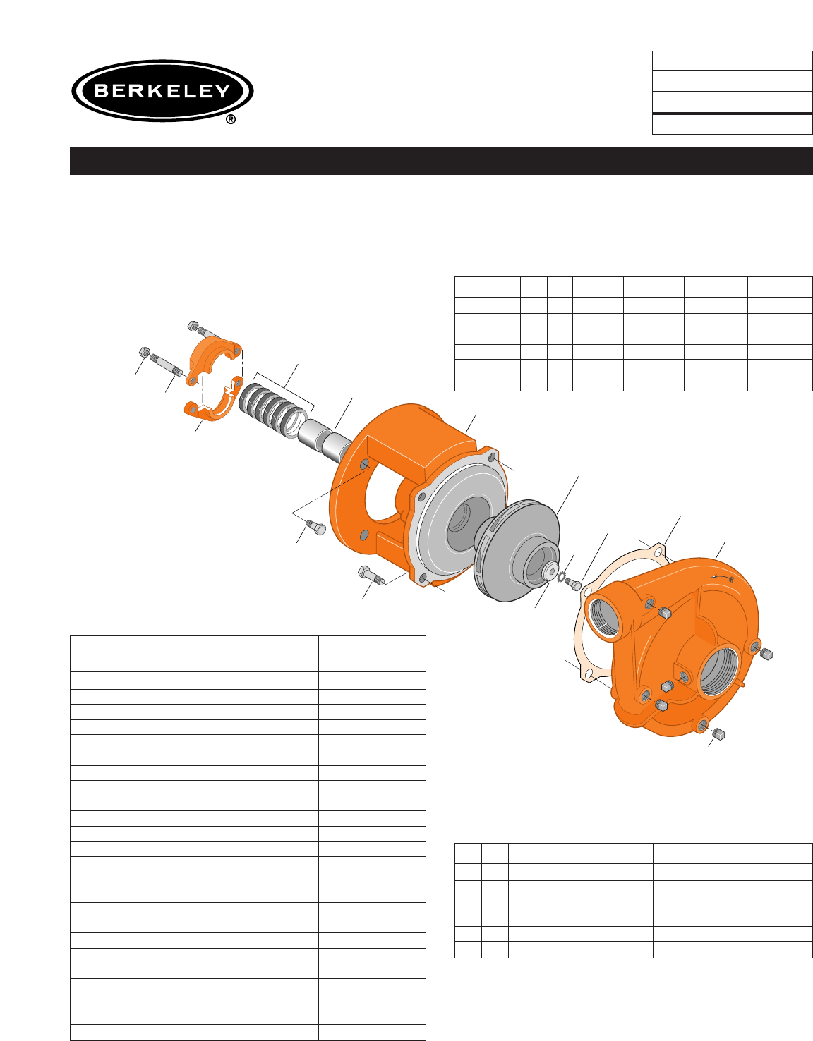
TYPE ‘‘B’’ SINGLE STAGE
CENTRIFUGAL PUMP
Electric Motor Drive
Section CC
Page 30.3
Date January 1, 2004
Supersedes 6/1/95
BRONZE IMPELLER B1-1/2TPM
Threaded Case (NPT) Packing Construction
NOTE: For an explanation of the tabulated material
found on this page and for impeller key location, refer to
Supplement A located at the beginning of this section.
Form No. S4855BK
Item
No. Part Description Part Number
1Case, Volute L01018
2Impeller See Table I
13A Rings, Packing (Set of 6) S13469
13B Rings, Packing (Set of 6) S13470
14A Sleeve, Shaft (2 Req.) S00619
14B Sleeve, Shaft S05149
17A Gland, Packing B82469
17B Gland, Packing B82470
26A Screw, Impeller, 3/8 - 16 x 1” S23566
26B Screw, Impeller 1/2 - 13 x 1” S23619
32A Key, 3/16 x 1-1/4” (See Note) S34383
32B Key, 1/4 x 2-1/4” (See Note) S23677
69A Washer, Impeller S16239
69B Washer, Impeller S06317
71 Bracket See Table II
73 Gasket, Volute S04757
800A Capscrew, 1/2 - 13 x 1” (4 Req.) S26912
800B Capscrew, 1/2 - 13 x 1” (8 Req.) S26912
800C Capscrew, 3/8 - 16 x 7/8” (4 Req.) S26825
801A Stud, 3/8 - 16 x 4” (2 Req.) S08303
801B Stud, 3/8 - 16 x 3-1/2” (2 Req.) S04441
802 Nut, Hex 3/8 - 16 (2 Req.) S23343
805 Washer, Lock S23038
810 Plug, Pipe 1/4 NPT (5 Req.) S23715
TABLE I
B/M No. HP PH RPM ‘‘U’’ Dim. Imp. Dia. Imp. No.
B66475 51 3600 7/8” 5.50” L08179
B66476 53 3600 7/8” 5.50” L08179
B66479 7.5 1 3600 1-1/4” 6.00” L08151
B66480 7.5 3 3600 7/8” 6.00” L08177
B66483 10 1 3600 1-1/4” 6.56” L08150
B66484 10 3 3600 1-1/4” 6.56” L08150
TABLE II
HP PH Bracket No. ‘‘AK’’ Fit ‘‘U’’ Dim. Motor Frame
51 L01525 4-1/2” 7/8” 184JP
53 L01525 4-1/2” 7/8” 182JP
7.5 1 L01951 8-1/2” 1-1/4” 213JP
7.5 3 L01525 4-1/2” 7/8” 184JP
10 1 L01951 8-1/2” 1-1/4” 215JP
10 3 L01951 8-1/2” 1-1/4” 213JP
T
r
u
a
r
c
1
810
815
800A
800B
71
26
69
73
2
14
89
1479 0195
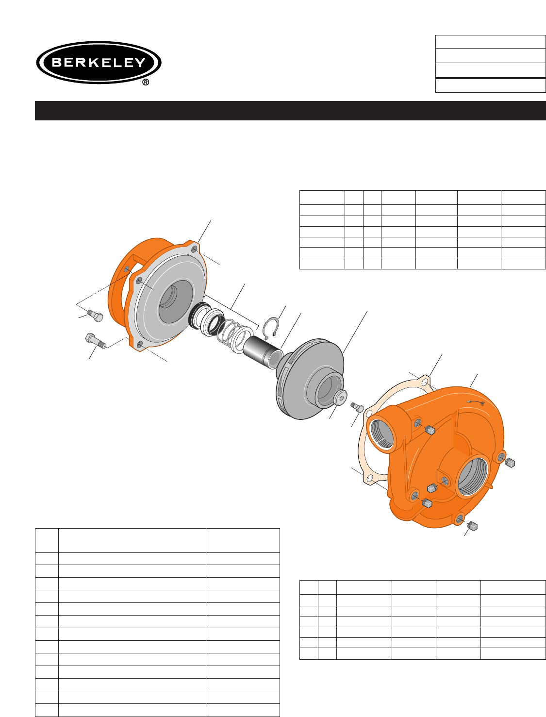
TYPE ‘‘B’’ SINGLE STAGE
CENTRIFUGAL PUMP
Electric Motor Drive
Section CC
Page 30.4
Date January 1, 2004
Supersedes 6/1/95
BRONZE IMPELLER B1-1/2TPMS
Threaded Case (NPT) Mechanical Shaft Seal Construction
NOTE: For an explanation of the tabulated material
found on this page and for impeller key location, refer to
Supplement A located at the beginning of this section.
Form No. S4855BK
TABLE I
B/M No. HP PH RPM ‘‘U’’ Dim. Imp. Dia. Imp. No.
B66477 51 3600 7/8” 5.50” L08179
B66478 53 3600 7/8” 5.50” L08179
B66481 7.5 1 3600 7/8” 6.00” L08177
B66482 7.5 3 3600 7/8” 6.00” L08177
B66485 10 1 3600 7/8” 6.56” L08176
B66486 10 3 3600 7/8” 6.56” L08176
TABLE II
HP PH Bracket No. ‘‘AK’’ Fit ‘‘U’’ Dim. Motor Frame
51 L05329 4-1/2” 7/8” 184JM
53 L05329 4-1/2” 7/8” 182JM
7.5 1 L05328 8-1/2” 7/8” 213JM
7.5 3 L05329 4-1/2” 7/8” 184JM
10 1 L05328 8-1/2” 7/8” 215JM
10 3 L05328 8-1/2” 7/8” 213JM
Item
No. Part Description Part Number
1Case, Volute L01018
2Impeller See Table I
14 Sleeve, Shaft S19310
26 Screw, Impeller 3/8 - 16 x 1” S23566
32 Key, 3/16 x 1-1/4” (See Note) S34383
69 Washer, Impeller S16239
71 Bracket See Table II
73 Gasket, Volute S04757
89 Seal, Mechanical Shaft S32014
800A Capscrew, 1/2 - 13 x 1” (8 Req.) S26912
800B Capscrew, 3/8 - 16 x 1” (4 Req.) S26826
810 Plug, Pipe 1/4 NPT (5 Req.) S23715
815 Ring, Retaining S11207

1
810
800A
71
26A (7/8 U)
26B (1-1/4 U)
69A (7/8 U)
69B (1-1/4 U)
73
2
14A (7/8 U)
14B (1-1/4 U)
13B (1-1/4 U)
13A (7/8 U)
17A (7/8 U)
17B (1-1/4 U)
1719 0495
800B (7/8 U)
800C (1-1/4U)
801A (7/8 U)
801B (1-1/4 U)
802
805
TYPE ‘‘B’’ SINGLE STAGE
CENTRIFUGAL PUMP
Electric Motor Drive
Section CC
Page 30.5
Date January 1, 2004
Supersedes 9/1/97
SILICON BRONZE IMPELLER B1-1/2TPM
Threaded Case (NPT) Packing Construction
NOTE: For an explanation of the tabulated material
found on this page and for impeller key location, refer to
Supplement A located at the beginning of this section.
Form No. S4855BK
Item
No. Part Description Part Number
1Case, Volute L01018
2Impeller See Table I
13A Rings, Packing (Set of 6) S13469
13B Rings, Packing (Set of 6) S13470
14A Sleeve, Shaft (2 Req.) S00619
14B Sleeve, Shaft S05149
17A Gland, Packing B82469
17B Gland, Packing B82470
26A Screw, Impeller, 3/8 - 16 x 1” S23566
26B Screw, Impeller 1/2 - 13 x 1” S23619
32A Key, 3/16 x 1-1/4” (See Note) S34383
32B Key, 1/4 x 2-1/4” (See Note) S23677
69A Washer, Impeller S16239
69B Washer, Impeller S06317
71 Bracket See Table II
73 Gasket, Volute S04757
800A Capscrew, 1/2 - 13 x 1” (4 Req.) S26912
800B Capscrew, 3/8 - 16 x 7/8” (4 Req.) S26825
800C Capscrew, 1/2 - 13 x 1” (4 Req.) S26912
801A Stud, 3/8 - 16 x 4” (2 Req.) S08303
801B Stud, 3/8 - 16 x 3-1/2” (2 Req.) S04441
802 Nut, Hex 3/8 - 16 (2 Req.) S23343
805 Washer, Lock S23038
810 Plug, Pipe 1/4” NPT (5 Req.) S23715
TABLE I
B/M No. HP PH RPM ‘‘U’’ Dim. Imp. Dia. Imp. No.
B74394 51 3600 7/8” 5.50” L08179
B74393 53 3600 7/8” 5.50” L08179
B74401 7.5 1 3600 1-1/4” 6.00” L08151
B74405 7.5 3 3600 7/8” 6.00” L08177
B74414 10 1 3600 1-1/4” 6.56” L08150
B74413 10 3 3600 1-1/4” 6.56” L08150
TABLE II
HP PH Bracket No. ‘‘AK’’ Fit ‘‘U’’ Dim. Motor Frame
51 L01525 4-1/2” 7/8” 184JP
53 L01525 4-1/2” 7/8” 182JP
7.5 1 L01951 8-1/2” 1-1/4” 213JP
7.5 3 L01525 4-1/2” 7/8” 184JP
10 1 L01951 8-1/2” 1-1/4” 215JP
10 3 L01951 8-1/2” 1-1/4” 213JP
T
r
u
a
r
c
1
810
815
800A
800B (4 1/2 AK)
800C (8 1/2 AK)
71
26
69
73
2
14
89
1479A 0195
TYPE ‘‘B’’ SINGLE STAGE
CENTRIFUGAL PUMP
Electric Motor Drive
Section CC
Page 30.6
Date January 1, 2004
Supersedes 9/1/97
SILICON BRONZE IMPELLER B1-1/2TPMS
Threaded Case (NPT) Mechanical Shaft Seal Construction
NOTE: For an explanation of the tabulated material
found on this page and for impeller key location, refer to
Supplement A located at the beginning of this section.
NOTE: For seal flush line details, see Supplement D.
Form No. S4855BK
TABLE I
B/M No. HP PH RPM ‘‘U’’ Dim. Imp. Dia. Imp. No.
B74397 51 3600 7/8” 5.50” L08179
B74396 53 3600 7/8” 5.50” L08179
B74409 7.5 1 3600 7/8” 6.00” L08177
B74407 7.5 3 3600 7/8” 6.00” L08177
B74419 10 1 3600 7/8” 6.56” L08176
B74418 10 3 3600 7/8” 6.56” L08176
TABLE II
HP PH Bracket No. ‘‘AK’’ Fit ‘‘U’’ Dim. Motor Frame
51 L05329 4-1/2” 7/8” 184JM
53 L05329 4-1/2” 7/8” 182JM
7.5 1 L05328 8-1/2” 7/8” 213JM
7.5 3 L05329 4-1/2” 7/8” 184JM
10 1 L05328 8-1/2” 7/8” 215JM
10 3 L05328 8-1/2” 7/8” 213JM
Item
No. Part Description Part Number
1Case, Volute L01018
2Impeller See Table I
14 Sleeve, Shaft S19310
26 Screw, Impeller 3/8 - 16 x 1” S23566
32 Key, 3/16 x 1-1/4” (See Note) S34383
69 Washer, Impeller S16239
71 Bracket See Table II
73 Gasket, Volute S04757
89 Seal, Mechanical Shaft S32014
800A Capscrew, 1/2 - 13 x 1” (4 Req.) S26912
800B Capscrew, 3/8 - 16 x 1” (4 Req.) S26826
800C Capscrew, 1/2 - 13 x 1” (4 Req.) S26912
810 Plug, Pipe 1/4” NPT (5 Req.) S23715
815 Ring, Retaining S11207
•Plug, Pipe 1/8” NPT (In Bracket) S23714
• Not illustrated.
