89272 5 Berkeley B83194 Repair Parts I
89273 5 Berkeley B83189 Repair Parts I 89273_5_Berkeley B83189 Repair Parts I
89269 5 Berkeley B83188 Repair Parts I 89269_5_Berkeley B83188 Repair Parts I
89268 5 Berkeley B83193 Repair Parts I 89268_5_Berkeley B83193 Repair Parts I
89270 5 Berkeley B83186 Repair Parts I 89270_5_Berkeley B83186 Repair Parts I
89265 5 Berkeley B83191 Repair Parts I 89265_5_Berkeley B83191 Repair Parts I
: Pump 89272 5 Berkeley B83194 Repair Parts I 89272_5_Berkeley B83194 Repair Parts I pdf
Open the PDF directly: View PDF ![]() .
.
Page Count: 8
17
801
802 14
29
9
1
73A
26
805
69
2
73B
115
73C
7
810
800A
1765 0495
811
812
800B
800B
800C
71
13
See Supplement B
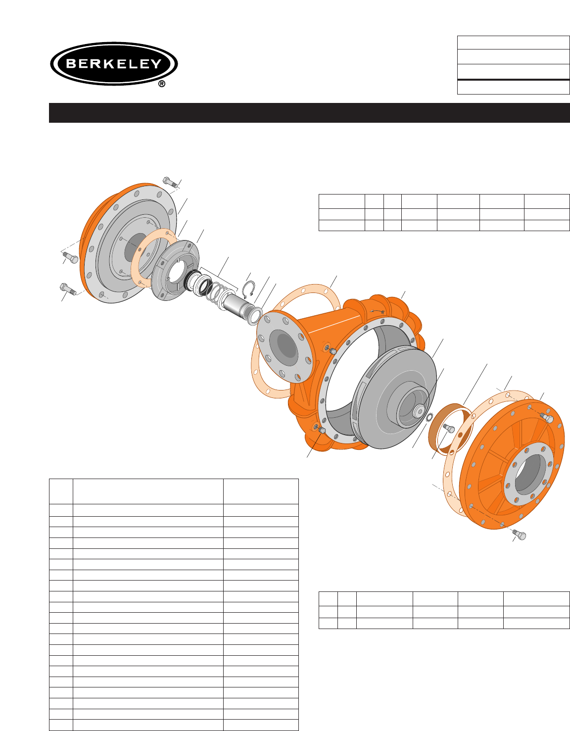
TYPE ‘‘B’’ SINGLE STAGE
CENTRIFUGAL PUMP
Electric Motor Drive
Section CC
Page 290.1
Date June 1, 1995
Supersedes/New
CAST IRON IMPELLER B4EYPBM
Flanged Case Packing Construction
NOTE: For an explanation of the tabulated material
found on this page and for impeller key location, refer to
Supplement A located at the beginning of this section.
Item
No. Part Description Part Number
1Case, Volute L01536
2Impeller See Table I
7 Ring, Wearing S15718
9 Cover, Suction L01541
13 Rings, Packing (Set of 4) S13435
14 Sleeve, Shaft S05149
17 Gland, Packing S12034
26 Screw, Impeller 1/2 - 13 x 1” S23619
29 Ring, Lantern S19200
32 Key, 1/4 x 2-1/4” (See Note) S23677
69 Washer, Impeller S06319
71 Bracket See Table II
73A Gasket, Suction Cover S06401
73B Gasket, Volute S06271
73C Gasket, Balance Ring S09943
115 Ring, Balance S13655
800A Capscrew, 5/8 - 11x1-3/4” (16 Req.) S27001
800B Capscrew, 5/8 - 11 x 1-1/2” (16 Req.) S26999
800C Capscrew, 3/8 - 16 x 1-1/2” (4 Req.) S26830
801 Stud, 3/8 - 16 x 2-1/2” (2 Req.) S04438
802 Nut, Hex 3/8 - 16 (2 Req.) S23343
805 Washer, Lock S23038
810 Plug, Pipe 1/2 NPT (4 Req.) S23717
811 Fitting, Grease S23700
812 Elbow, Street S25421
TABLE I
B/M No. HP PH RPM ‘‘U’’ Dim. Imp. Dia. Imp. No.
B51738 40 3 1800 1-1/4” 14.44” L06185
B51739 50 3 1800 1-1/4” 15.06” L06186
TABLE II
HP PH Bracket No. ‘‘AK’’ Fit ‘‘U’’ Dim. Motor Frame
40 3 H01601 12-1/2” 1-1/4” 324JP
50 3 H01601 12-1/2” 1-1/4” 326JP
73A
73B
800A
2
71 A
69
26
7
805A
17
801
802 14
29 115
73C
811
812
800B
800B
800C
71B
13
See Supplement B
1
810
5177 1105
TYPE ‘‘B’’ SINGLE STAGE
CENTRIFUGAL PUMP
Electric Motor Drive
Section CC
Page 290.1.1
Date December 1, 2005
Supersedes 1/1/04
CAST IRON IMPELLER B4EYPBM
Flanged Case Packing Construction
NOTE: For an explanation of the tabulated material
found on this page and for impeller key location, refer to
Supplement A located at the beginning of this section.
Item
No. Part Description Part Number
1Case, Volute M13751
2Impeller See Table I
7 Ring, Wearing S15718
13 Rings, Packing (Set of 4) S13435
14 Sleeve, Shaft S05149
17 Gland, Packing B82470
26 Screw, Impeller 1/2 - 13 x 1” S23619
29 Ring, Lantern S19200
32 Key, 1/4 x 2-1/4” (See Note) S23677
69 Washer, Impeller S06319
71A Ring, Adapter M13753
71B Bracket See Table II
73A Gasket, Suction Cover S06401
73B Gasket, Volute S06271
73C Gasket, Balance Ring S09943
115 Ring, Balance S13655
800A Capscrew, 5/8 - 11x1-3/4” (16 Req.) S27001
800B Capscrew, 5/8 - 11 x 1-1/2” (16 Req.) S26999
800C Capscrew, 3/8 - 16 x 1-1/2” (4 Req.) S26830
801 Stud, 3/8 - 16 x 2-1/2” (2 Req.) S04438
802 Nut, Hex 3/8 - 16 (2 Req.) S23343
805 Washer, Lock S23038
810 Plug, Pipe 1/2 NPT (4 Req.) S23717
811 Fitting, Grease S23700
812 Elbow, Street S25421
TABLE I
B/M No. HP PH RPM ‘‘U’’ Dim. Imp. Dia. Imp. No.
B83191 40 3 1800 1-1/4” 14.44” L06185
B83195 50 3 1800 1-1/4” 15.06” L06186
TABLE II
HP PH Bracket No. ‘‘AK’’ Fit ‘‘U’’ Dim. Motor Frame
40 3 H01601 12-1/2” 1-1/4” 324JP
50 3 H01601 12-1/2” 1-1/4” 326JP
29
17
801
802 14
24 (100HP)
9
1
73A
26
805
69
2
73B
115
73C
7
810
800A
1766 0495
811
812
800B
800B
800C
71
13
See Supplement B
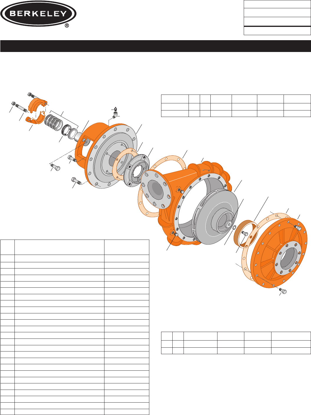
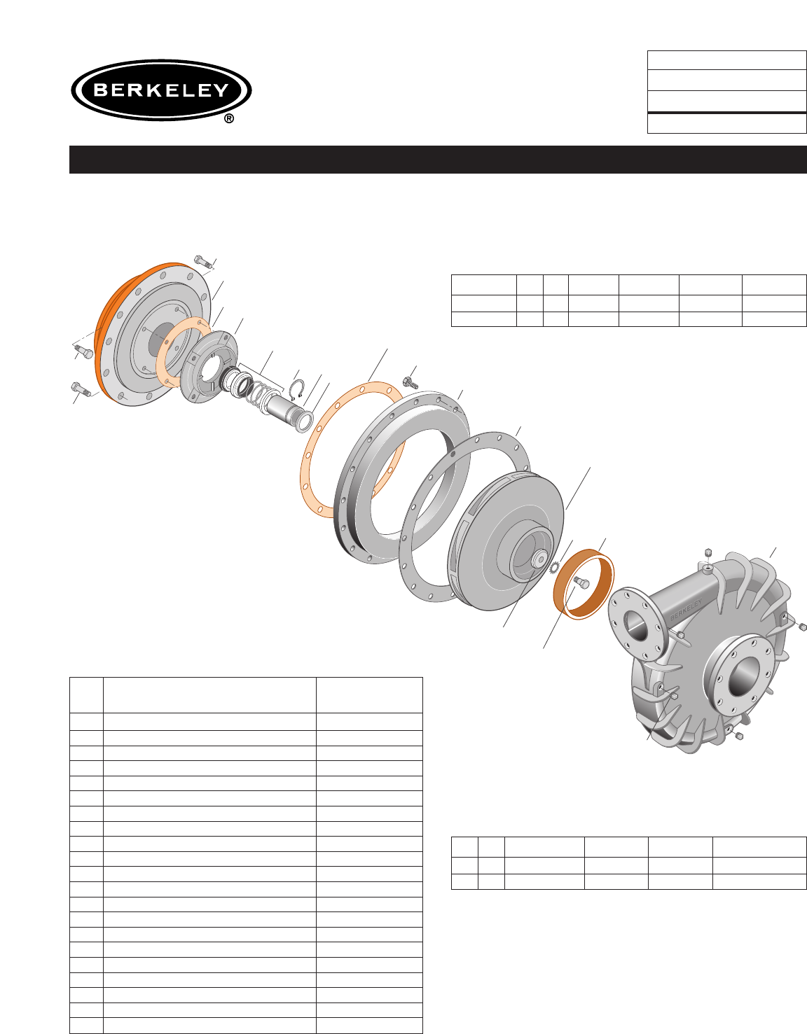
TYPE ‘‘B’’ SINGLE STAGE
CENTRIFUGAL PUMP
Electric Motor Drive
Section CC
Page 290.2
Date November 2, 2009
Supersedes 1/1/04
CAST IRON IMPELLER B4EYPBM
Flanged Case Packing Construction
NOTE: For an explanation of the tabulated material
found on this page and for impeller key location, refer to
Supplement A located at the beginning of this section.
Form No. S4855BK
Item
No. Part Description Part Number
1 Case, Volute L01536
2 Impeller See Table I
7 Ring, Wearing S15718
9 Cover, Suction L01541
13 Rings, Packing (Set of 4) S13437
14 Sleeve, Shaft S07073L
17 Gland, Packing B82471
24 Locknut, Impeller S07829
26 Screw, Impeller 1/2 - 13 x 1-1/4” S23621
29 Ring, Lantern S19198
32 Key, 3/8 x 2-1/4” (See Note) S23940
69 Washer, Impeller S34492
71 Bracket See Table II
73A Gasket, Suction Cover S06401
73B Gasket, Volute S06271
73C Gasket, Balance Ring S09943
115 Ring, Balance S13655
800A Capscrew, 5/8 - 11 x 1-3/4” (20 Req.) S27001
800B Capscrew, 5/8 - 11 x 1-1/2” (12 Req.) S26999
800C Capscrew, 3/8 - 16 x 1-1/2” (4 Req.) S26830
801 Stud, 3/8 - 16 x 2-1/2” (2 Req.) S04438
802 Nut, Hex 3/8 - 16 (2 Req.) S23343
805 Washer, Lock S23038
810 Plug, Pipe 1/2 NPT (4 Req.) S23717
811 Fitting, Grease S23700
812 Elbow, Street S25421
TABLE I
B/M No. HP PH RPM ‘‘U’’ Dim. Imp. Dia. Imp. No.
BB555599777760 3 1800 1-5/8” 16.00” L06187
BB555599778875 3 1800 1-5/8” 16.94” L06188
BB5555997799100 3 1800 1-5/8” 17.88” L02425
TABLE II
HP PH Bracket No. ‘‘AK’’ Fit ‘‘U’’ Dim. Motor Frame
60 3 H03622 12-1/2” 1-5/8” 364JP
75 3 H03622 12-1/2” 1-5/8” 365JP
100 3 H03622 12-1/2” 1-5/8” 404TC
73A
73B
800A
2
71A
69
26
7
805A
29
17
801
802 14
24 (100HP)
115
73C
811
812
800B
800B
800C
71A
13
See Supplement B
1
810
5178 1105
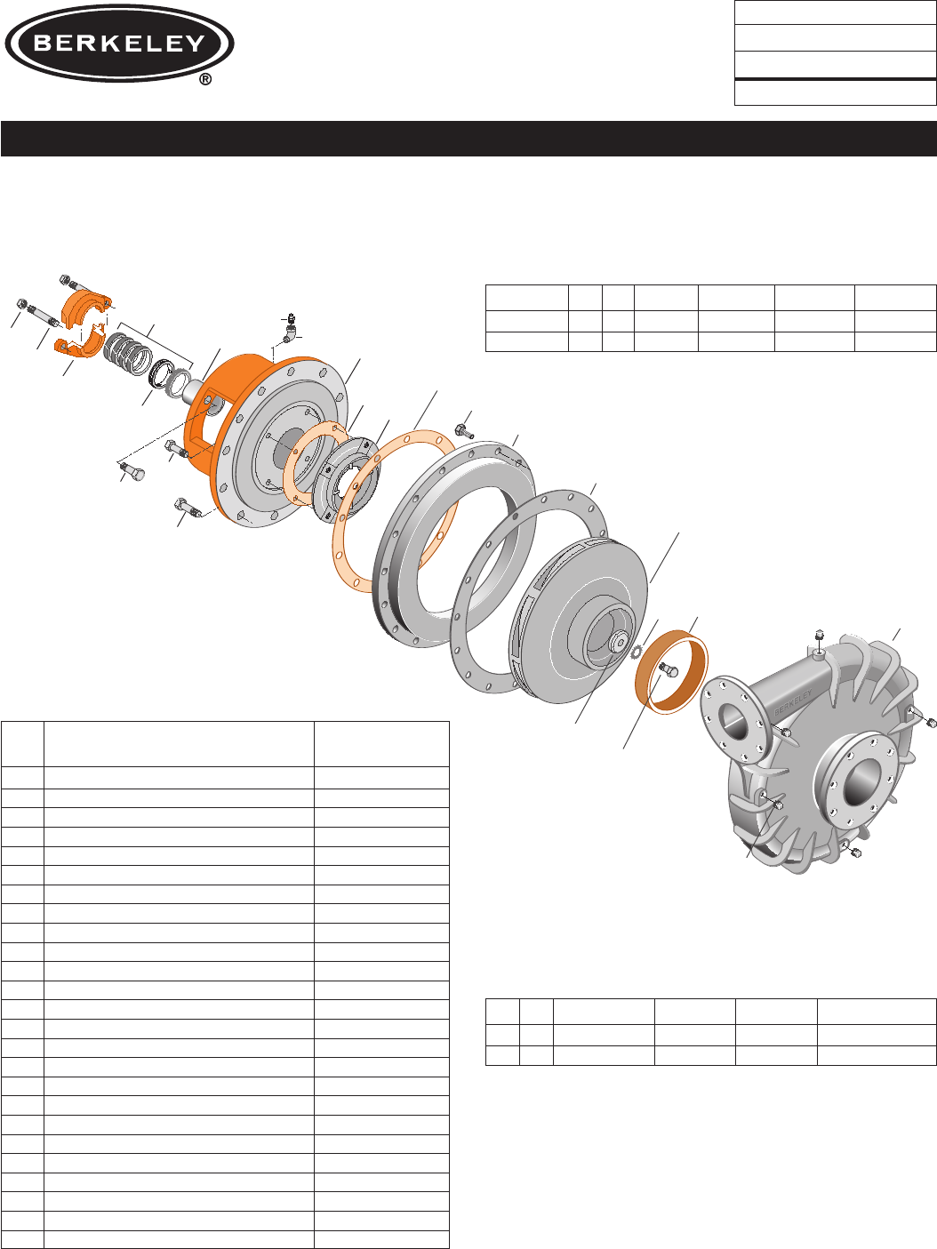
TYPE ‘‘B’’ SINGLE STAGE
CENTRIFUGAL PUMP
Electric Motor Drive
Section CC
Page 290.2.1
Date November 2, 2009
Supersedes 12/1/05
CAST IRON IMPELLER B4EYPBM
Flanged Case Packing Construction
NOTE: For an explanation of the tabulated material
found on this page and for impeller key location, refer to
Supplement A located at the beginning of this section.
Form No. S4855BK
Item
No. Part Description Part Number
1 Case, Volute M13751
2 Impeller See Table I
7 Ring, Wearing S15718
13 Rings, Packing (Set of 4) S13437
14 Sleeve, Shaft S07073L
17 Gland, Packing B82471
24 Locknut, Impeller S07829
26 Screw, Impeller 1/2 - 13 x 1-1/4” S23621
29 Ring, Lantern S19198
32 Key, 3/8 x 2-1/4” (See Note) S23940
69 Washer, Impeller S34492
71A Ring, Adapter M13753
71B Bracket See Table II
73A Gasket, Suction Cover S06401
73B Gasket, Volute S06271
73C Gasket, Balance Ring S09943
115 Ring, Balance S13655
800A Capscrew, 5/8 - 11 x 1-3/4” (20 Req.) S27001
800B Capscrew, 5/8 - 11 x 1-1/2” (12 Req.) S26999
800C Capscrew, 3/8 - 16 x 1-1/2” (4 Req.) S26830
801 Stud, 3/8 - 16 x 2-1/2” (2 Req.) S04438
802 Nut, Hex 3/8 - 16 (2 Req.) S23343
805 Washer, Lock S23038
810 Plug, Pipe 1/2 NPT (4 Req.) S23717
811 Fitting, Grease S23700
812 Elbow, Street S25421
TABLE I
B/M No. HP PH RPM ‘‘U’’ Dim. Imp. Dia. Imp. No.
B83192 60 3 1800 1-5/8” 16.00” L06187
B83193 75 3 1800 1-5/8” 16.94” L06188
B83188 100 3 1800 1-5/8” 17.88” L02425
TABLE II
HP PH Bracket No. ‘‘AK’’ Fit ‘‘U’’ Dim. Motor Frame
60 3 H03622 12-1/2” 1-5/8” 364JP
75 3 H03622 12-1/2” 1-5/8” 365JP
100 3 H03622 12-1/2” 1-5/8” 404TC
T
r
u
a
r
c
9
1
73A
26
805
69
2
73B
67
815
89
115
800B
800B
73C
800C
71
7
810
800A
1699 0295
14
TYPE ‘‘B’’ SINGLE STAGE
CENTRIFUGAL PUMP
Electric Motor Drive
Section CC
Page 290.3
Date January 1, 2004
Supersedes 6/1/95
CAST IRON IMPELLER B4EYPBMS
Flanged Case Mechanical Shaft Seal Construction
NOTE: For an explanation of the tabulated material
found on this page and for impeller key location, refer to
Supplement A located at the beginning of this section.
Form No. S4855BK
TABLE I
B/M No. HP PH RPM ‘‘U’’ Dim. Imp. Dia. Imp. No.
B54183 40 3 1800 1-1/4” 14.44” L06185
B54184 50 3 1800 1-1/4” 15.06” L06186
TABLE II
HP PH Bracket No. ‘‘AK’’ Fit ‘‘U’’ Dim. Motor Frame
40 3 H03301 12-1/2” 1-1/4” 324JM
50 3 H03301 12-1/2” 1-1/4” 326JM
Item
No. Part Description Part Number
1Case, Volute L01536
2Impeller See Table I
7Ring, Wearing S15718
9Cover, Suction L01541
14 Sleeve, Shaft S18869
26 Screw, Impeller 1/2 - 13 x 1-1/4’’ S23621
32 Key, 1/4 x 2-1/4” (See Note) S23677
67 Ring, Spacer S19349
69 Washer, Impeller S06319
71 Bracket See Table II
73A Gasket, Suction Cover S06401
73B Gasket, Volute Case S06271
73C Gasket, Blanace Ring S09943
89 Seal, Mechanical Shaft S32015
115 Ring, Balance S19036
800A Capscrew, 5/8 - 11 x 1-3/4” (16 Req.) S27001
800B Capscrew, 5/8 - 11 x 1-1/2” (16 Req.) S26999
800C Capscrew, 3/8 - 16 x 1” (4 Req.) S26826
805 Washer, Lock S23038
810 Plug, Pipe 1/2 NPT (4 Req.) S23717
815 Ring, Retaining S16767
T
r
u
a
r
c
67
815
89
115
800B
800B
73C
800C
71B
5179 1105
14
73A
73B
800A
2
71A
69
26
7
805A 1
810
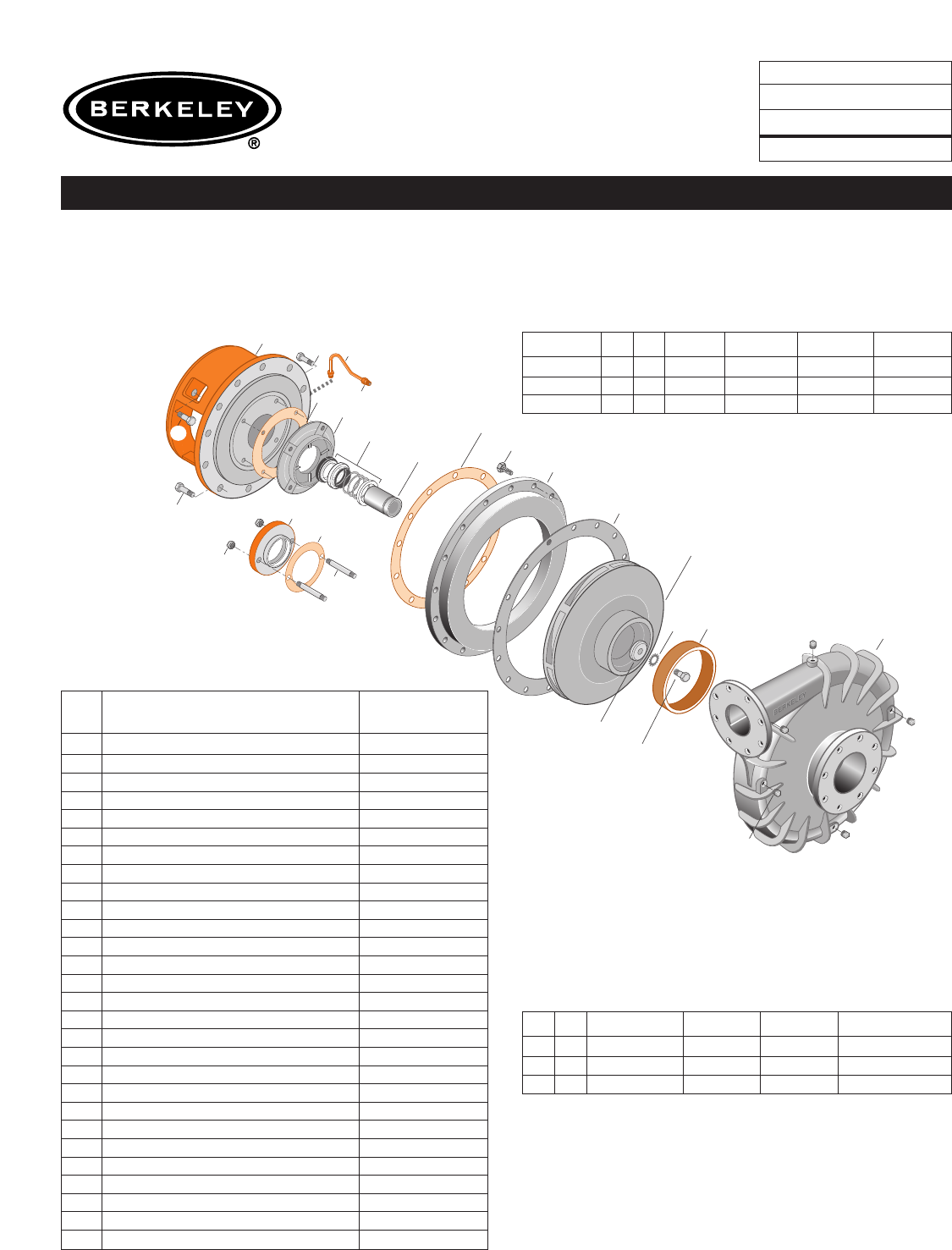
TYPE ‘‘B’’ SINGLE STAGE
CENTRIFUGAL PUMP
Electric Motor Drive
Section CC
Page 290.3.1
Date November 2, 2009
Supersedes 12/1/05
CAST IRON IMPELLER B4EYPBMS
Flanged Case Mechanical Shaft Seal Construction
NOTE: For an explanation of the tabulated material
found on this page and for impeller key location, refer to
Supplement A located at the beginning of this section.
Form No. S4855BK
TABLE I
B/M No. HP PH RPM ‘‘U’’ Dim. Imp. Dia. Imp. No.
B8318640 3 1800 1-1/4” 14.44” L06185
B8318750 3 1800 1-1/4” 15.06” L06186
TABLE II
HP PH Bracket No. ‘‘AK’’ Fit ‘‘U’’ Dim. Motor Frame
40 3 H03301 12-1/2” 1-1/4” 324JM
50 3 H03301 12-1/2” 1-1/4” 326JM
Item
No. Part Description Part Number
1 Case, Volute M13751
2 Impeller See Table I
7 Ring, Wearing S15718
14 Sleeve, Shaft S18869L
26 Screw, Impeller 1/2 - 13 x 1-1/4’’ S23621
32 Key, 1/4 x 2-1/4” (See Note) S23677
67 Ring, Spacer S19349
69 Washer, Impeller S06319
71A Ring, Adapter M13753
71B Bracket See Table II
73A Gasket, Suction Cover S06401
73B Gasket, Volute Case S06271
73C Gasket, Blanace Ring S09943
89 Seal, Mechanical Shaft S32015
115 Ring, Balance S19036
800A Capscrew, 5/8 - 11 x 1-3/4” (16 Req.) S27001
800B Capscrew, 5/8 - 11 x 1-1/2” (16 Req.) S26999
800C Capscrew, 3/8 - 16 x 1” (4 Req.) S26826
805 Washer, Lock S23038
810 Plug, Pipe 1/2 NPT (4 Req.) S23717
815 Ring, Retaining S16767
820
822
Seal Flush Line
Shown twice scale.
9
1
73A
26
805
69
2
73B
14
89
115
800B
73C
800D
71
7
810
800A
802
801
11
13
Detail of Mechanical
Seal Retainer
800C
1700 0295
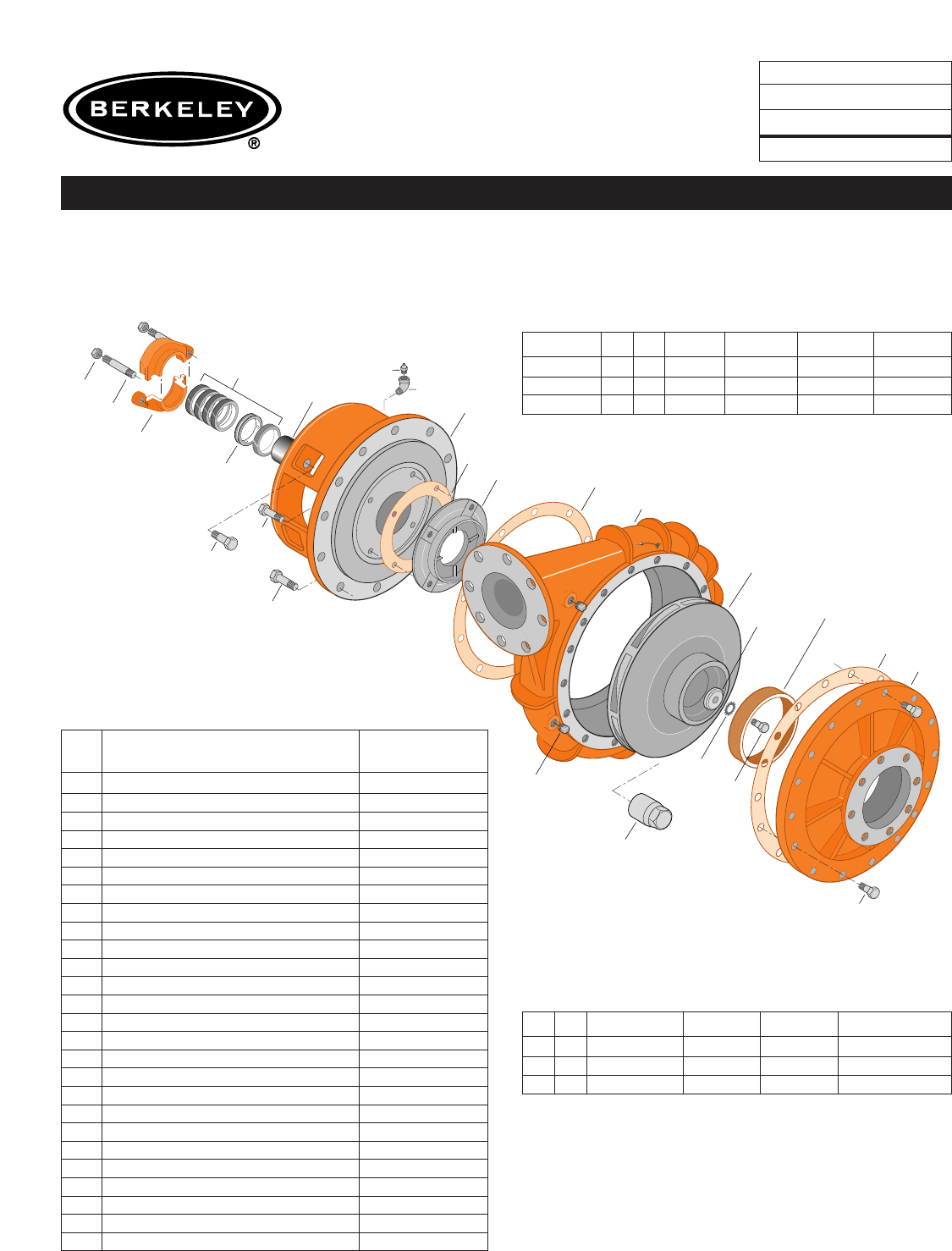
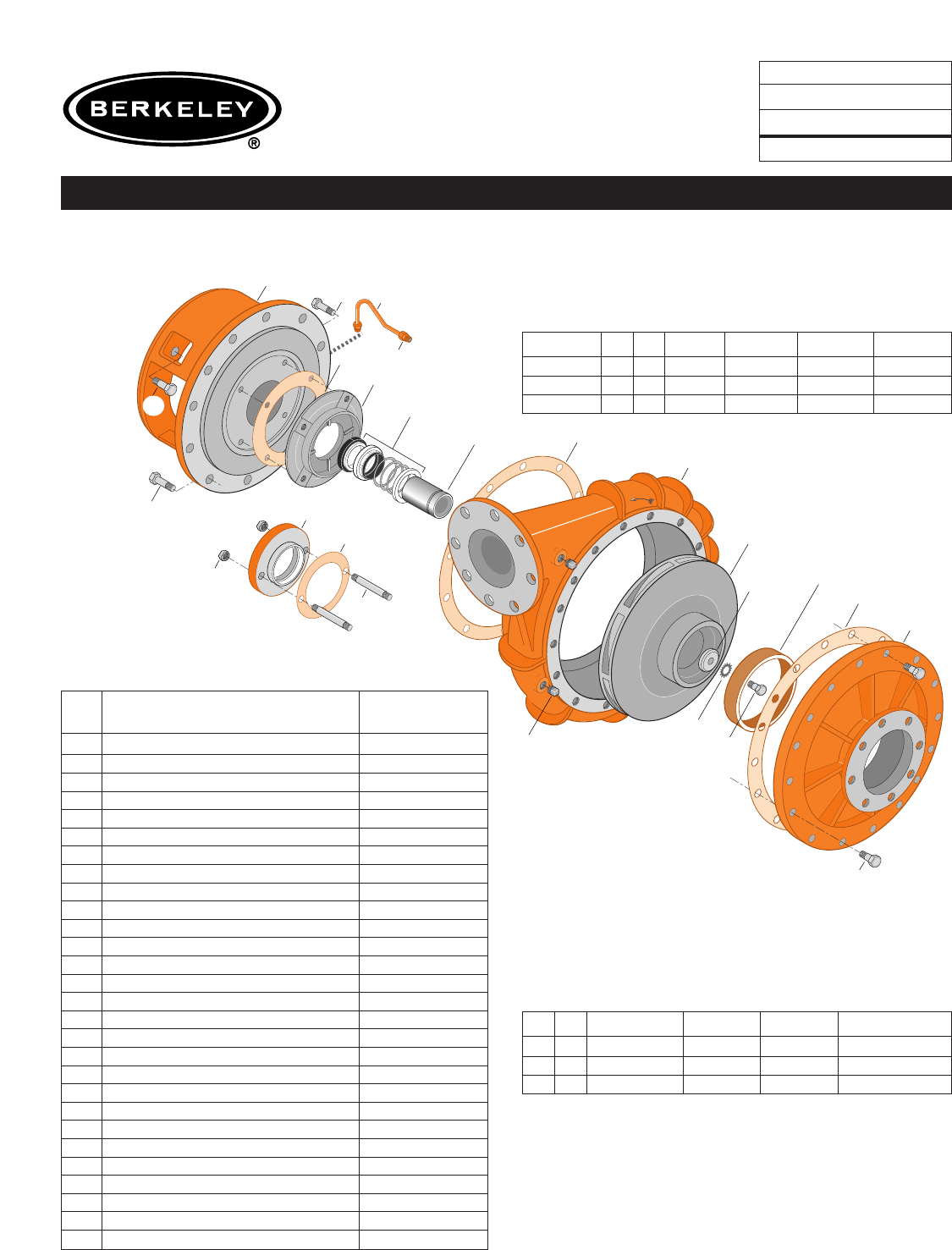
TYPE ‘‘B’’ SINGLE STAGE
CENTRIFUGAL PUMP
Electric Motor Drive
Section CC
Page 290.4
Date January 1, 2004
Supersedes 6/1/95
CAST IRON IMPELLER B4EYPBMS
Flanged Case Mechanical Shaft Seal Construction
NOTE: For an explanation of the tabulated material
found on this page and for impeller key location, refer to
Supplement A located at the beginning of this section.
Form No. S4855BK
TABLE I
B/M No. HP PH RPM ‘‘U’’ Dim. Imp. Dia. Imp. No.
B62039 60 3 1800 1-5/8” 16.00” L06187
B62041 75 3 1800 1-5/8” 16.94” L06188
B62043 100 3 1800 1-5/8” 17.88” L02425
TABLE II
HP PH Bracket No. ‘‘AK’’ Fit ‘‘U’’ Dim. Motor Frame
60 3 H03936 12-1/2” 1-5/8” 364JP
75 3 H03936 12-1/2” 1-5/8” 365JP
100 3 H03936 12-1/2” 1-5/8” 404TC
Item
No. Part Description Part Number
1Case, Volute L01536
2Impeller See Table I
7Ring, Wearing S15718
9Cover, Suction L01541
11 Retainer, Mechanical Shaft Seal S15377
14 Sleeve, Shaft S07073
26 Screw, Impeller 1/2 - 13 x 1-1/4” S23621
32 Key, 1/4 x 2-1/4” (See Note) S23677
69 Washer, Impeller (60-75 HP) S34492
69 Washer, Impeller (100 HP) S07829
71 Bracket See Table II
73A Gasket, Suction Cover S06401
73B Gasket, Volute Case S06271
73C Gasket, Balance Ring S09943
73D Gasket, Seal Retainer S15078
89 Seal, Mechanical Shaft S32016
115 Ring, Balance S13655
800A Capscrew, 5/8 - 11 x 1-3/4” (20 Req.) S27001
800B Capscrew, 5/8 - 11 x 1-1/2” (12 Req.) S26999
800C Capscrew, 3/8 - 16 x 1-1/2” (4 Req.) S26830
801 Stud, 3/8 - 16 x 2-1/2” (2 Req.) S04438
802 Nut, 3/8 - 16 (2 Req.) S23343
805 Washer, Lock (Not On 100 HP) S23038
810 Plug, Pipe 1/2 NPT (4 Req.) S23717
820 Connector, Comp. Fitting (2 Req.) S24013
822 Tubing, Copper S20677
•Plug, Pipe 1/8 NPT (Not Illustrated) S23714
•Plug, Pipe 1/4 NPT (Not Illustrated) S23715
820
822 Seal Flush Line
Shown twice scale.
14
89
115
800B
73C
800D
71B
802
801
11
13
Detail of Mechanical
Seal Retainer
800C
5180 1105
73A
73B
800A
2
71A
69
26
7
805A 1
810
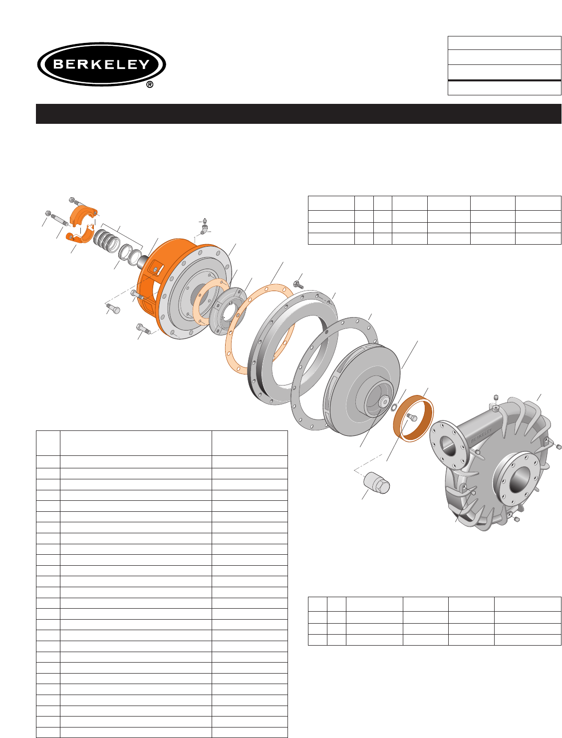
TYPE ‘‘B’’ SINGLE STAGE
CENTRIFUGAL PUMP
Electric Motor Drive
Section CC
Page 290.4.1
Date November 2, 2009
Supersedes 12/1/05
CAST IRON IMPELLER B4EYPBMS
Flanged Case Mechanical Shaft Seal Construction
NOTE: For an explanation of the tabulated material
found on this page and for impeller key location, refer to
Supplement A located at the beginning of this section.
Form No. S4855BK
TABLE I
B/M No. HP PH RPM ‘‘U’’ Dim. Imp. Dia. Imp. No.
B83194 60 3 1800 1-5/8” 16.00” L06187
B8318975 3 1800 1-5/8” 16.94” L06188
B83190 100 3 1800 1-5/8” 17.88” L02425
TABLE II
HP PH Bracket No. ‘‘AK’’ Fit ‘‘U’’ Dim. Motor Frame
60 3 H03936 12-1/2” 1-5/8” 364JP
75 3 H03936 12-1/2” 1-5/8” 365JP
100 3 H03936 12-1/2” 1-5/8” 404TC
Item
No. Part Description Part Number
1 Case, Volute M13751
2 Impeller See Table I
7 Ring, Wearing S15718
11 Retainer, Mechanical Shaft Seal S15377
14 Sleeve, Shaft S07073L
26 Screw, Impeller 1/2 - 13 x 1-1/4” S23621
32 Key, 1/4 x 2-1/4” (See Note) S23677
69 Washer, Impeller (60-75 HP) S34492
69 Washer, Impeller (100 HP) S07829
71A Ring, Adapter M13753
71B Bracket See Table II
73A Gasket, Suction Cover S06401
73B Gasket, Volute Case S06271
73C Gasket, Balance Ring S09943
73D Gasket, Seal Retainer S15078
89 Seal, Mechanical Shaft S32016
115 Ring, Balance S13655
800A Capscrew, 5/8 - 11 x 1-3/4” (20 Req.) S27001
800B Capscrew, 5/8 - 11 x 1-1/2” (12 Req.) S26999
800C Capscrew, 3/8 - 16 x 1-1/2” (4 Req.) S26830
801 Stud, 3/8 - 16 x 2-1/2” (2 Req.) S04438
802 Nut, 3/8 - 16 (2 Req.) S23343
805 Washer, Lock (Not On 100 HP) S23038
810 Plug, Pipe 1/2 NPT (4 Req.) S23717
820 Connector, Comp. Fitting (2 Req.) S24013
822 Tubing, Copper S20677
•Plug, Pipe 1/8 NPT (Not Illustrated) S23714
•Plug, Pipe 1/4 NPT (Not Illustrated) S23715
