Puretek Co PT-3030 Modem User Manual 3030
Puretek Industrial Co Ltd Modem 3030
users manual

Quick Installation GuideQuick Installation Guide
Quick Installation GuideQuick Installation Guide
Quick Installation Guide
VVVVVererererer. B 303. B 303
. B 303. B 303
. B 3036-0007
Fax ModemFax Modem
Fax ModemFax Modem
Fax Modem

Quick Installation GuideQuick Installation Guide
Quick Installation GuideQuick Installation Guide
Quick Installation Guide
VVVVVererererer. B 303. B 303
. B 303. B 303
. B 3036-0007
Fax ModemFax Modem
Fax ModemFax Modem
Fax Modem

FCC ComplianceFCC Compliance
FCC ComplianceFCC Compliance
FCC Compliance
To comply with the applicable sections of FCC
Rules and Regulations, Parts 68 and 15, please
follow these instructions:
§ Do not connect your modem to a party lineparty line
party lineparty line
party line
or to a coin-operatedcoin-operated
coin-operatedcoin-operated
coin-operated telephone.
§ If your modem should cause a problem on
the telephone line, it should be
disconnecteddisconnected
disconnecteddisconnected
disconnected from the line until it can be
determined whether the modem or
another device on the phone line caused
the problem.
§ Only the manufacturermanufacturer
manufacturermanufacturer
manufacturer can make repairs to
the modem. Other repair methods will void
your warranty.
§ If you have an external modem, use a
properly constructed shielded cableconstructed shielded cable
constructed shielded cableconstructed shielded cable
constructed shielded cable to
connect it to your computer.
§ If your telephone company asks for the
following information, please make it
available:
- Modem manufacturer
- Model of modem
- FCC Registration Number
- Ringer Equivalence Number (REN)
FCC Part 15FCC Part 15
FCC Part 15FCC Part 15
FCC Part 15
Operation is subject to the following two
conditions:
1. This device may not cause harmful
interference.
2. This device must accept any interference
received including interference that may
cause undesired operation.
This equipment has been tested and found to
comply with the limits for a Class B digital device,
pursuant to Part 15 of the FCC Rules. These limits
are designed to provide reasonable protection
against harmful interference when the equipment
is operated in a residential installation. This
equipment generates, uses, and can radiate
frequency energy and if not installed and used in
accordance with the instructions, may cause
harmful interference to radio communications.
However, there is no guarantee that the interfer-
ence to radio or television reception, which can be
determined by turning the equipment off and on,
the user is encouraged to try to correct the
interference by one or more of the following
measures:
§ Reorient or relocate the receiving antenna.
§ Increase the separation between the
equipment and receiver.
§ Connect the equipment into an outlet on a

circuit different from that to which the
receiver is connected.
§ Consult the dealer or an experienced radio/
TV technician for help.
Any changes or modifications not
expressly approved by the grantee of
this device could void the user authority
to operate the equipment.
FCC Part 68 NoticeFCC Part 68 Notice
FCC Part 68 NoticeFCC Part 68 Notice
FCC Part 68 Notice
This equipment complies with Part 68 of the FCC
rules. On the base of this unit is a label that
contains, among other information, the FCC
registration number and Ringer Equivalence
Number (REN) for this equipment. If requested,
this information must be given to your telephone
company.
The REN is used to determine the quantity of
devices you may connect to your telephone line
and still have all of those devices ring when your
number is called. In most, but not all areas, the
sum of the RENs of all devices should not exceed
five (5.0). To be certain of the number of devices
you may connect to your line, as determined by
the total RENs, you should call your local tel-
ephone company to determine the maximum RENs
for your calling area.
If the telephone company suspects a problem with
your telephone line is related to an add-on
Caution
!
electronic device, such as your modem, they have
the right to temporarily suspend your service. It is
your responsibility to remove from the telephone
line any malfunctioning electronic communications
equipment to avoid damage to the telephone
system.
If your equipment causes harm to the telephone
network, the telephone company may discontinue
your service temporarily. If possible, they will notify
you in advance. But if advance notice is not
practical, you will be notified as soon as possible.
You will be informed of your right to file a com-
plaint with the FCC. Your telephone company may
make changes to its facilities, equipment, opera-
tions, or procedures that could affect the proper
functioning of your equipment. If they do, you will
be notified in advance to give you an opportunity
to maintain uninterrupted telephone service.
The telephone company may ask that you discon-
nect this equipment from the network until the
problem has been corrected or until you are sure
that the equipment is not malfunctioning.
This equipment may not be used on coin service
provided by the telephone company. Connection
to party lines is subjected to state tariffs.
If you experience trouble with this telephone
equipment, please contact your place of purchase
for information on obtaining service or repairs.

TT
TT
Table of Contentsable of Contents
able of Contentsable of Contents
able of Contents
Chapter 1 IntroductionChapter 1 Introduction
Chapter 1 IntroductionChapter 1 Introduction
Chapter 1 Introduction
Your Modem ..................................... 1
Features............................................... 2
System Requirements......................... 2
Package Checklist .............................. 3
Chapter 2 InstallationsChapter 2 Installations
Chapter 2 InstallationsChapter 2 Installations
Chapter 2 Installations
Hardware Installation .............. ........... 4
Installation Procedures for
Windows NT4.0 driver ............ .......... 5
Installation Procedures for
Windows 98 driver ................. ......... 6
Installation of Procedures for
Windows 2000 driver ...................... 10
AT Command .................................... 11

Chapter 1
IntroductionIntroduction
IntroductionIntroduction
Introduction
The Voice/Fax/Data Modem connects your computer
to Internet, and all kinds of BBS, and other popular
Fax / Modems. This manual describes the features,
procedures of installations, and AT command set...
etc. of this modem.
YY
YY
Your modem...our modem...
our modem...our modem...
our modem...
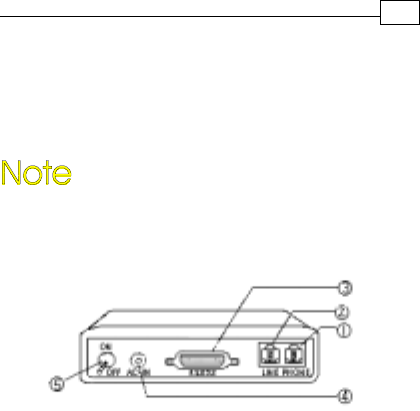
There are indicator lights and connectors on the
front and back side of this modem. Following is
the meaning of these light and connectors for
your reference:
1. External Front Panel 1. External Front Panel
1. External Front Panel 1. External Front Panel
1. External Front Panel
RD : Received Data indicator.
TD : Transmitted Data indicator.
CD : Carrier Detect indicator.
OH : Off Hook.
MR : Modem Ready.
PHONE : Phone jack.
LINE : Telephone line jack.
RS232 : RS232 cable socket.
AC-IN : AC adapter input.
ON/OFF : Power switch.
2. External Rear Panel2. External Rear Panel
2. External Rear Panel2. External Rear Panel
2. External Rear Panel
1

2
Chapter 1
FeaturesFeatures
FeaturesFeatures
Features
This modem supports the following communica-
tion standards. ITU-T is known as CCITT.
DataData
DataData
Data
ITU-T V.90
z ITU-T V.34, V.32bis, V.32, V.22bis, V.22
Bell 103 & 212A
V.42bis & MNP 5 ( Data compression )
V.42 & MNP2-4 ( Error correction )
FaxFax
FaxFax
Fax
V.17 ( 14400bps FAX )
V.29 ( 9600bps FAX )
V.27ter ( 4800bps FAX )
z
z
z
z
z
z
z
VV
VV
Voiceoice
oiceoice
oice
Voice/Audio mode
z
System RequirementsSystem Requirements
System RequirementsSystem Requirements
System Requirements
Windows NT 4.0, Windows 95, Windows 98,
Windows 2000.

3
Chapter 1
The package contains the following items:
One fax modem
One piece of phone cable
One CD
One AC Adaptop
The fax modem Quick Installation Guide
If any of these items are missing or damaged,
please contact your dealer or sales representative
for assistance.
z
z
One piece of RS-232 cable
z
z
z
Package ChecklistPackage Checklist
Package ChecklistPackage Checklist
Package Checklist
z

4
Chapter 2
InstallationsInstallations
InstallationsInstallations
Installations
This chapter describes how to install and power
on you fax modem.
Hardware InstallationHardware Installation
Hardware InstallationHardware Installation
Hardware Installation
Before complete the hardware installation
be aware not to power on the modem
1. Plug the male end of the RS-232RS-232
RS-232RS-232
RS-232 cable into
the connector marked RS-232RS-232
RS-232RS-232
RS-232 ( ) on the
back of the modem.
2. Plug the other end of this cable into the
serial port on the back of your computer.
3. ( Be sure your modem is Power off ) Plug
the power cable into the AC-INAC-IN
AC-INAC-IN
AC-IN connector
( ) on the back of the modem.
e
f
4. Plug the power adapter into a wall outlet.

5
Chapter 2
7. Turn your modem on( ). The MR MR
MR MR
MR lights
should light up.
8. Turn your computer on.
g
5. Plug one end of the phone cable into the
modem‘s LINELINE
LINELINE
LINE jack ( ). Plug the other end
into the phone outlet.
6. To use telephone and the modem on the
same line, plug one end of the optional
phone cable into the PHONE PHONE
PHONE PHONE
PHONE jack( ) on
the modem; plug the other end into the
phone. Lift the telephone handset and listen
for a DIALDIAL
DIALDIAL
DIALTONE TONE
TONE TONE
TONE to check the connection.
Windows NT4.0 DriverWindows NT4.0 Driver
Windows NT4.0 DriverWindows NT4.0 Driver
Windows NT4.0 Driver
c
d
1. When enter to the Winnt operating system,
select the modem item in the control panel,
the following dialog box will appear, please
select “do not detect my modem…”, then
click Next.
2. Select install from disk, the following dialog
box appear, please specify the path of the
driver, e.g. D:\Drivers\winnt4, then click
Next.
3. Varies type of modems will show in a dialog
box, please select ( “Topic 56000bps External
Fax Voice Modem”), then click Next.
Installation Procedures forInstallation Procedures for
Installation Procedures forInstallation Procedures for
Installation Procedures for
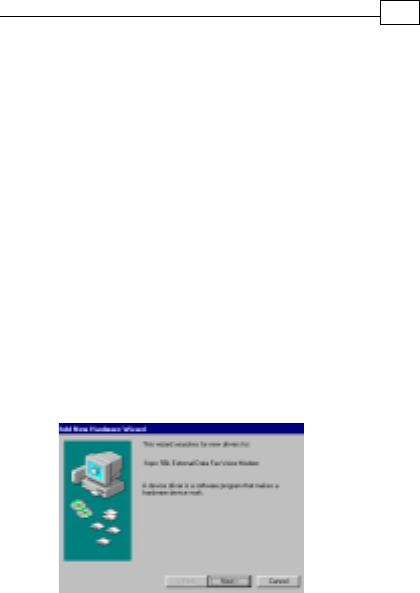
1. Once you have completed the hardware
installation, power on your computer.
When running Win 98, your system will
detect a new device and the following
message will appear. click Next .
6
Chapter 2
4. Please select the COM port which attach to
your modem, then click Next
5. You have installed the modem successfully .
6. If you want to configure the setting of your
modem, please select the modem item in
the control panel, a dialog box with modem
status will appear.
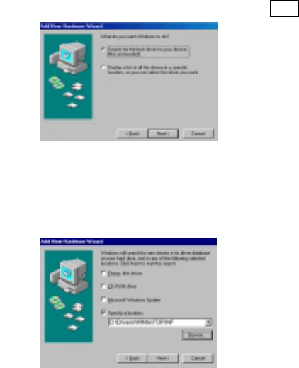
2. Select the “search for the best driver for
your device (Recommended)” option, then
click Next .
Installation ProceduresInstallation Procedures
Installation ProceduresInstallation Procedures
Installation Procedures for for
for for
for
Windows 98 DirverWindows 98 Dirver
Windows 98 DirverWindows 98 Dirver
Windows 98 Dirver

7
Chapter 2
3. Place the disk containing the driver of Win 9X
into your floppy disk drive. Specify the
location of the modem driver, e.g.
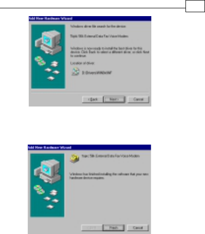
D:\Drivers\WIN9x\TOP.INF . click Next .
4. The following message will appear. click
Next .

5. The installation has been completed. click
Finish.
8
Chapter 2
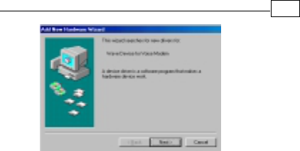
6. After the installation of Fax Voice Modem
was completed, your system will detect Wave
Device for Voice Modem and the following
message will appear . click Next and
then you could follow Step2 to Step5 to
finish the installation .
9
Chapter 2

Installation Procedures forInstallation Procedures for
Installation Procedures forInstallation Procedures for
Installation Procedures for
1. Once you have completed the hardware
installation, power on your computer. When
running Win 2000, your system will detect a
new device. click Next.
2. Select the “search for the best driver for your
device (Recommended) “option, then click
Next.
3. Place the disk containing the driver of Win 2000
into your floppy disk drive. Select the “specify
location”, then click Next.
4. Browse the proper location of the driver path,
e.g. D:\Drivers\WIN2000, then cilck Next.
5. Click Nexit.
6. Please read the Digital Signature, then click
Yes.
7. To complete the installation, click Finish.
10
Chapter 2
Windows 2000Windows 2000
Windows 2000Windows 2000
Windows 2000 Driver Driver
Driver Driver
Driver

11
Chapter 2
AA
AA
AT CommandT Command
T CommandT Command
T Command
Most people use the communication software
programs to tell modems what to do. Therefore,
you may not use the commands in this chapter.
However, if you prefer to communicate with your
modem directly, you can type the commands
described below.
This chapter describes how to work in the
terminal mode.
The disk contains detail of AT commands.
(file path:D :\ATCOMMAND.PDF)
PK-MAN-0142

TT
TT
Table of Contentsable of Contents
able of Contentsable of Contents
able of Contents
Chapter 1 IntroductionChapter 1 Introduction
Chapter 1 IntroductionChapter 1 Introduction
Chapter 1 Introduction
Your Modem ..................................... 1
Features............................................... 2
System Requirements......................... 2
Package Checklist .............................. 3
Chapter 2 InstallationsChapter 2 Installations
Chapter 2 InstallationsChapter 2 Installations
Chapter 2 Installations
Hardware Installation .............. ........... 4
Installation Procedures for
Windows NT4.0 driver ............ .......... 5
Installation Procedures for
Windows 98 driver ................. ......... 6
Installation of Procedures for
Windows 2000 driver ...................... 10
AT Command .................................... 11

Chapter 1
IntroductionIntroduction
IntroductionIntroduction
Introduction
The Voice/Fax/Data Modem connects your computer
to Internet, and all kinds of BBS, and other popular
Fax / Modems. This manual describes the features,
procedures of installations, and AT command set...
etc. of this modem.
YY
YY
Your modem...our modem...
our modem...our modem...
our modem...
There are indicator lights and connectors on the
front and back side of this modem. Following is
the meaning of these light and connectors for
your reference:
1. External Front Panel 1. External Front Panel
1. External Front Panel 1. External Front Panel
1. External Front Panel
RD : Received Data indicator.
TD : Transmitted Data indicator.
CD : Carrier Detect indicator.
OH : Off Hook.
MR : Modem Ready.
PHONE : Phone jack.
LINE : Telephone line jack.
RS232 : RS232 cable socket.
AC-IN : AC adapter input.
ON/OFF : Power switch.
2. External Rear Panel2. External Rear Panel
2. External Rear Panel2. External Rear Panel
2. External Rear Panel
1

2
Chapter 1
FeaturesFeatures
FeaturesFeatures
Features
This modem supports the following communica-
tion standards. ITU-T is known as CCITT.
DataData
DataData
Data
ITU-T V.90
z ITU-T V.34, V.32bis, V.32, V.22bis, V.22
Bell 103 & 212A
V.42bis & MNP 5 ( Data compression )
V.42 & MNP2-4 ( Error correction )
FaxFax
FaxFax
Fax
V.17 ( 14400bps FAX )
V.29 ( 9600bps FAX )
V.27ter ( 4800bps FAX )
z
z
z
z
z
z
z
VV
VV
Voiceoice
oiceoice
oice
Voice/Audio mode
z
System RequirementsSystem Requirements
System RequirementsSystem Requirements
System Requirements
Windows NT 4.0, Windows 95, Windows 98,
Windows 2000.

3
Chapter 1
The package contains the following items:
One fax modem
One piece of phone cable
One CD
One AC Adaptop
The fax modem Quick Installation Guide
If any of these items are missing or damaged,
please contact your dealer or sales representative
for assistance.
z
z
One piece of RS-232 cable
z
z
z
Package ChecklistPackage Checklist
Package ChecklistPackage Checklist
Package Checklist
z
4
Chapter 2
InstallationsInstallations
InstallationsInstallations
Installations
This chapter describes how to install and power
on you fax modem.
Hardware InstallationHardware Installation
Hardware InstallationHardware Installation
Hardware Installation
Before complete the hardware installation
be aware not to power on the modem
1. Plug the male end of the RS-232RS-232
RS-232RS-232
RS-232 cable into
the connector marked RS-232RS-232
RS-232RS-232
RS-232 ( ) on the
back of the modem.
2. Plug the other end of this cable into the
serial port on the back of your computer.
3. ( Be sure your modem is Power off ) Plug
the power cable into the AC-INAC-IN
AC-INAC-IN
AC-IN connector
( ) on the back of the modem.
e
f
4. Plug the power adapter into a wall outlet.

5
Chapter 2
7. Turn your modem on( ). The MR MR
MR MR
MR lights
should light up.
8. Turn your computer on.
g
5. Plug one end of the phone cable into the
modem‘s LINELINE
LINELINE
LINE jack ( ). Plug the other end
into the phone outlet.
6. To use telephone and the modem on the
same line, plug one end of the optional
phone cable into the PHONE PHONE
PHONE PHONE
PHONE jack( ) on
the modem; plug the other end into the
phone. Lift the telephone handset and listen
for a DIALDIAL
DIALDIAL
DIALTONE TONE
TONE TONE
TONE to check the connection.
Windows NT4.0 DriverWindows NT4.0 Driver
Windows NT4.0 DriverWindows NT4.0 Driver
Windows NT4.0 Driver
c
d
1. When enter to the Winnt operating system,
select the modem item in the control panel,
the following dialog box will appear, please
select “do not detect my modem…”, then
click Next.
2. Select install from disk, the following dialog
box appear, please specify the path of the
driver, e.g. D:\Drivers\winnt4, then click
Next.
3. Varies type of modems will show in a dialog
box, please select ( “Topic 56000bps External
Fax Voice Modem”), then click Next.
Installation Procedures forInstallation Procedures for
Installation Procedures forInstallation Procedures for
Installation Procedures for

1. Once you have completed the hardware
installation, power on your computer.
When running Win 98, your system will
detect a new device and the following
message will appear. click Next .
6
Chapter 2
4. Please select the COM port which attach to
your modem, then click Next
5. You have installed the modem successfully .
6. If you want to configure the setting of your
modem, please select the modem item in
the control panel, a dialog box with modem
status will appear.
2. Select the “search for the best driver for
your device (Recommended)” option, then
click Next .
Installation ProceduresInstallation Procedures
Installation ProceduresInstallation Procedures
Installation Procedures for for
for for
for
Windows 98 DirverWindows 98 Dirver
Windows 98 DirverWindows 98 Dirver
Windows 98 Dirver
7
Chapter 2
3. Place the disk containing the driver of Win 9X
into your floppy disk drive. Specify the
location of the modem driver, e.g.
D:\Drivers\WIN9x\TOP.INF . click Next .
4. The following message will appear. click
Next .
5. The installation has been completed. click
Finish.
8
Chapter 2
6. After the installation of Fax Voice Modem
was completed, your system will detect Wave
Device for Voice Modem and the following
message will appear . click Next and
then you could follow Step2 to Step5 to
finish the installation .

9
Chapter 2

Installation Procedures forInstallation Procedures for
Installation Procedures forInstallation Procedures for
Installation Procedures for
1. Once you have completed the hardware
installation, power on your computer. When
running Win 2000, your system will detect a
new device. click Next.
2. Select the “search for the best driver for your
device (Recommended) “option, then click
Next.
3. Place the disk containing the driver of Win 2000
into your floppy disk drive. Select the “specify
location”, then click Next.
4. Browse the proper location of the driver path,
e.g. D:\Drivers\WIN2000, then cilck Next.
5. Click Nexit.
6. Please read the Digital Signature, then click
Yes.
7. To complete the installation, click Finish.
10
Chapter 2
Windows 2000Windows 2000
Windows 2000Windows 2000
Windows 2000 Driver Driver
Driver Driver
Driver

11
Chapter 2
AA
AA
AT CommandT Command
T CommandT Command
T Command
Most people use the communication software
programs to tell modems what to do. Therefore,
you may not use the commands in this chapter.
However, if you prefer to communicate with your
modem directly, you can type the commands
described below.
This chapter describes how to work in the
terminal mode.
The disk contains detail of AT commands.
(file path:D :\ATCOMMAND.PDF)
PK-MAN-0142