Pyott Boone Electronics PAS400 125 kHz Transceiver User Manual PAS
Pyott Boone Electronics, Inc. 125 kHz Transceiver PAS
Manual
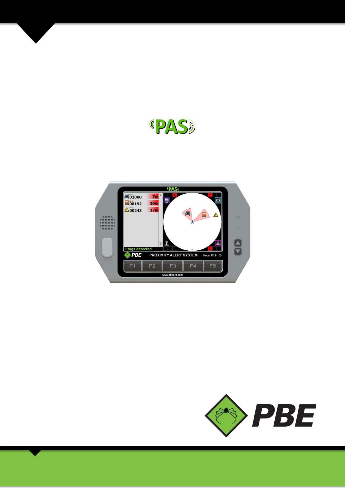
MODEL PAS
Proximity Alert System
MANUAL: 004-0352-001-A
Rev: 1
INNOVATING SAFETY
POWERING PRODUCTIVITY
sales@pbegrp.com
www.pbegrp.com

Model PAS Proximity Alert System Manual Page 2 of 25
TABLE OF CONTENTS
1. WARRANTY ............................................................................................................................................................... 3
2. INTRODUCTION ......................................................................................................................................................... 3
3. INSTALLATION ........................................................................................................................................................... 5
VEHICLE INSTALLATION ..................................................................................................................................................................... 5
PAS CONTROLLER SETUP .................................................................................................................................................................. 5
Units ....................................................................................................................................................................................... 6
Volume ................................................................................................................................................................................... 7
Vehicle Dimensions ................................................................................................................................................................. 7
Sensor Locations ..................................................................................................................................................................... 8
Zones ...................................................................................................................................................................................... 8
Audible Alerts ......................................................................................................................................................................... 9
Visual Alerts .......................................................................................................................................................................... 10
Linked Tags ........................................................................................................................................................................... 10
PAS Display Setup ................................................................................................................................................................. 11
Geofences ............................................................................................................................................................................. 12
Compass ............................................................................................................................................................................... 15
System .................................................................................................................................................................................. 16
Detection .............................................................................................................................................................................. 16
Relay Outputs ....................................................................................................................................................................... 17
Passcode ............................................................................................................................................................................... 17
About .................................................................................................................................................................................... 18
4. OPERATION ............................................................................................................................................................. 19
SWITCHING ON ............................................................................................................................................................................. 19
DISCLAIMER ................................................................................................................................................................................. 19
EQUIPMENT DETECTION ................................................................................................................................................................. 19
USING THE CONTROLLER PAS SCREEN ............................................................................................................................................... 20
PAS Screen Area Coverage ................................................................................................................................................... 20
Zoomed-out Coverage View ................................................................................................................................................. 20
Zoomed-in Coverage View .................................................................................................................................................... 22
Urgent Alarm ........................................................................................................................................................................ 22
Caution Alarm ....................................................................................................................................................................... 23
Geofence Alarm .................................................................................................................................................................... 23
VIDEO ......................................................................................................................................................................................... 23
VEHICLE OCCUPANTS ..................................................................................................................................................................... 24
NOTIFICATIONS ............................................................................................................................................................................. 24
OTHER FEATURES .......................................................................................................................................................................... 24
Event Log .............................................................................................................................................................................. 24
MAINTENANCE ............................................................................................................................................................................. 24
Copyright © 2014 PBE Inc. All rights reserved. No section or element of this document may be removed from this
document, reproduced, electronically stored or transmitted in any form without the written permission of PBE. The
information contained in this document produced by PBE, is solely for the use of the client(s) for the purpose for which
it has been prepared and PBE undertakes no duty to, nor accepts any responsibility to, any third party who may rely
upon this information contained in this document.
Model PAS Proximity Alert System Manual Page 3 of 25
1. WARRANTY
The Proximity Alert System has a 12 month warranty period on all components. This warranty covers any defects which
prove to be in materials and/or workmanship. This warranty shall be considered void on any unit which has been
subjected to misuse, neglect, or accident or used in violation of instructions. Modifications of this unit will void any and
all warranty, implied, expressed or written. Any defect should be brought to the attention of PBE, whereupon
arrangements will be made to repair or replace the unit at the discretion of PBE.
2. INTRODUCTION
PBE’s Proximity Alert System (PAS) is designed to enhance workplace safety by reducing risk of collision through asset
and personnel detection and warning. The system incorporates overlapping detection technologies (RFID, GPS,
Electromagnetic sensors, and (optional) real-time video surveillance) for redundancy and safety to detect user defined
Heavy Vehicles, Light Vehicles, Personnel and Obstacles.
PBE’s PAS provides the driver with greater situational awareness which leads to increased safety and comfort.
The system can be easily integrated into PBE’s tracking system with MineBoss™ compatible tags and can provide
monitoring and reporting.
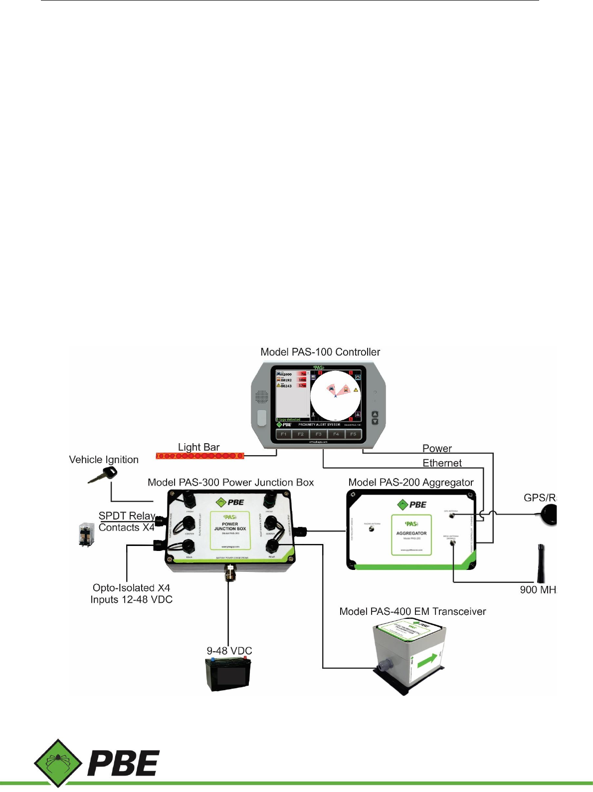
The Proximity Alert System comprises several major components (see Figure 1).
Figure 1: PAS system diagram

Model PAS Proximity Alert System Manual Page 4 of 25
Controller (Model PAS-100) – in-cab user interface with touchscreen and speaker (and attached light bar).
Aggregator (Model PAS-200) – data collection point for the various sensor technologies. There is a 12 pin circular
connector for receiving power and EM transceiver data from the PAS-300 Power Junction Box and an Ethernet port for
connection to the PAS-100 PAS Controller. GPS and Mesh antenna connection are located on the top.
Power Junction Box (Model PAS-300) – supplies power to the PAS-100 Controller, PAS-200 Aggregator and up to 6 PAS-
400 EM transceivers. Connection made through interconnected cables. One main power input (battery). One
transmit/receive data connection with the Aggregator. Power triggered by vehicle ignition switch.
Electromagnetic Transceiver (Model PAS-400) – generates and receives electromagnetic fields for accurate, close
proximity object detection. Up to six transceivers may be connected to the Junction Box (PAS-300).
PAS Texting Tag (Model PAS-500) – serves as a tracking tag to track/locate personnel, equipment, etc. The Tag sends
customized and canned messages to MineBoss™ and has a panic/warning mode for sending emergency notifications to
MineBoss™. The Tag has a rechargeable NiMH battery, two status LEDs, tri-axial EM receiver and GPS.
For more information visit our website or request a Technical Datasheet from your local sales representative.
Model PAS Proximity Alert System Manual Page 5 of 25
3. INSTALLATION
Vehicle Installation
Vehicle installation should only be performed by suitably qualified and authorized personnel. Installation will vary at
each site and with each different vehicle model.
The Controller should be mounted in the cabin of the vehicle to be in clear view of the driver without obscuring their
vision. Ideally the Controller would be close enough for the driver to see the details on the screen and be able to touch
the screen.
The Aggregator and Power Junction Box can be placed inside the cabin (space permitting) or outside the cabin in a
secure position so as to avoid damage. PBE can supply protective enclosures for these components.
EM sensors should be installed evenly around the side of the vehicle with the label facing outward and the text upright.
To ensure the sensor is vertical a panel may need to be welded to the side of the vehicle. The amount of sensors will
vary depending on the size of the vehicle, however, the normal installation assumes four or six sensors.
PAS Controller Setup
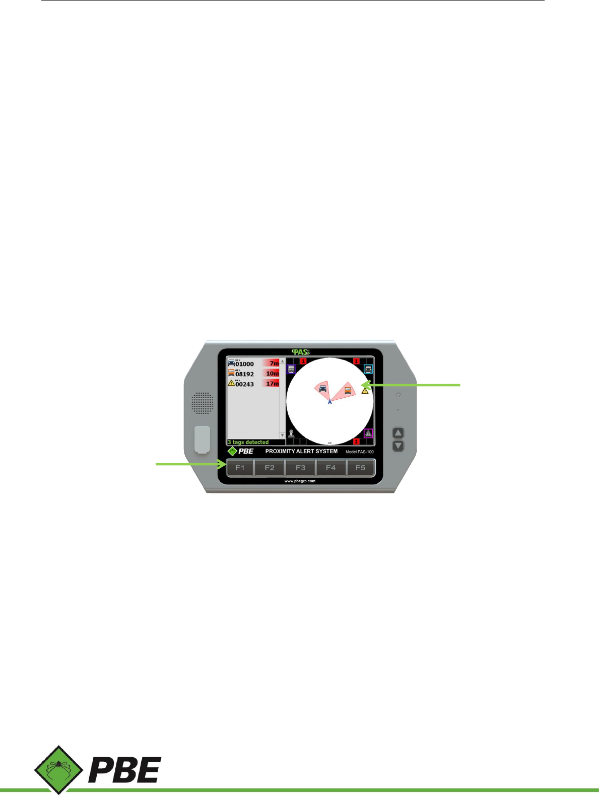
From the PAS screen, press F1 to access the Main Menu (see Figure 2 below).
The fully functional touch screen on the Controller (Model PAS-100) can be used to select setup options. On each of
the setup screens select ‘Done’ to return to the Setup Menu or ‘Next’ to continue to the next option. When finished
making changes press F1 to commit (save) those changes or F5 to discard them and return to the PAS screen.
Figure 2: PAS Controller hotkeys
PAS screen
Hotkeys
Model PAS Proximity Alert System Manual Page 6 of 25
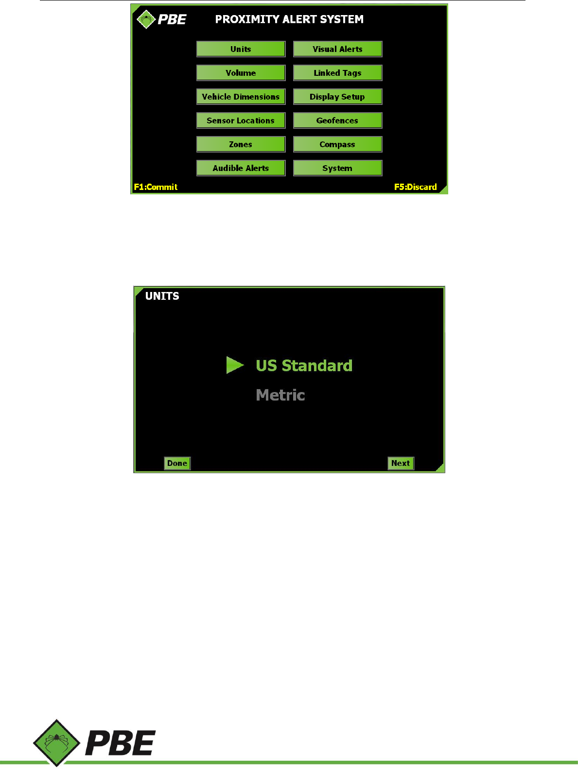
Figure 3: Main Menu
The following describes each of the setup options.
Units
Figure 4: Units menu screen
Select the desired units of measurement (US Standard or Metric) to be displayed throughout the application. The green
arrow highlights the selection.
Model PAS Proximity Alert System Manual Page 7 of 25
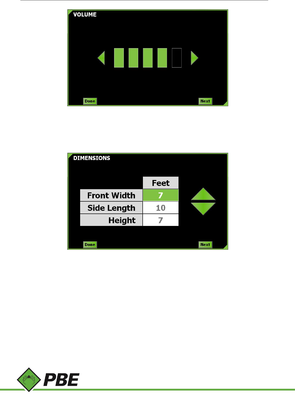
Volume
Figure 5: Volume menu screen
Select the speaker volume level by tapping the arrows to increase or decrease the volume.
Vehicle Dimensions
Figure 6: Dimensions menu screen
Enter the dimensions of the vehicle. Tap the displayed dimension for front width, then use the up and down arrows to
change the value. Repeat for vehicle side length and height. The vehicle should just fit inside the rectangular prism
formed by the dimensions. Vehicle articulation is not supported.
Model PAS Proximity Alert System Manual Page 8 of 25
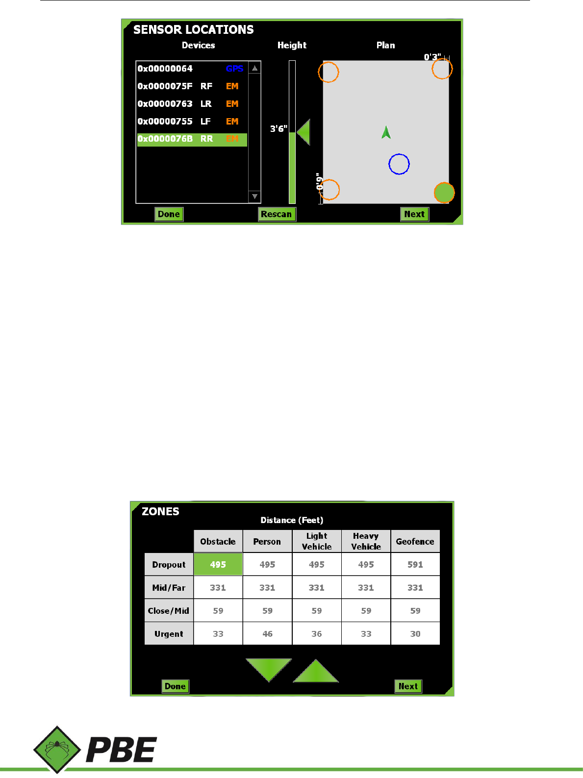
Sensor Locations
Figure 7: Sensor Locations menu screen
Sensors installed on the vehicle are displayed in the Devices list on the left (LF = Left Front; RF = Right Front; LC = Left
Center; RC = Right Center; LR = Left Rear; RR = Right Rear). Each sensor must be selected separately, and then the actual
height it was installed on the vehicle is represented on the Height bar by dragging the green arrow up or down.
The actual position of each sensor on the vehicle will also need to be represented in the Plan view (depicted by the grey
box on the right of the screen). Drag the sensor’s corresponding circle (highlighted in green) to its actual installation
location on the vehicle. Use the measurements given on the side, as the box is not to scale.
The EM sensors are represented by orange circles. The GPS antenna location is represented by a blue circle. Faulty
sensors are colored red.
To delete a sensor from the list, if it is no longer required (eg. damaged), right-click or tap and hold the item in the
Devices list.
Press the Rescan button to get immediate feedback about all currently connected sensors. If the Rescan button is
colored red, it means there is no connection to the PAS-200 Aggregator.
Zones
Figure 8: Zones menu screen
Model PAS Proximity Alert System Manual Page 9 of 25
The Dropout zone is the artificial maximum range beyond which objects will disappear from the PAS screen. Its purpose
is to limit distraction and reduce on-screen clutter by dropping objects that are not in the vicinity of the driver, which
would otherwise be displayed due to the extended tag communications range.
The Mid/Far and Close/Mid values define the two boundaries between three arbitrary range classification zones; Close,
Mid and Far. The Mid/Far value must be higher than the Close/Mid value. The number of objects in each of these three
zones is indicated in the four corners of the PAS screen for each object type. Each of the three zones has its own color,
which is used to highlight the object’s distance displayed in the tag list; Close is red, Mid is orange and Far is yellow.
The Urgent zone defines the range within which an object will trigger the urgent alarm, light bar flashing and on-screen
highlighting of the object. The alarm can be acknowledged by pressing the PAS screen.
To change a value, tap on the desired panel and then use the up and down arrows.
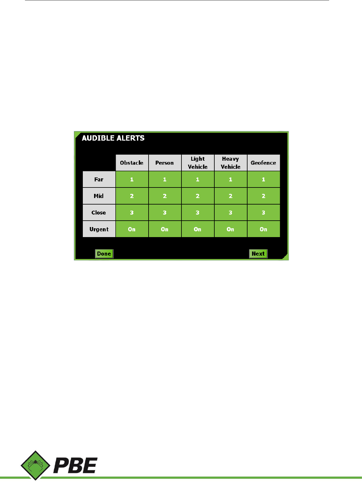
Audible Alerts
Figure 9: Audible Alerts menu screen
Select the amount of beeps sounded when an object comes into each specified zone. To change the value, tap on the
desired panel and cycle through the options: 1, 2, 3, or Off (then back to 1…). The Urgent alarm is either On or Off.
Model PAS Proximity Alert System Manual Page 10 of 25
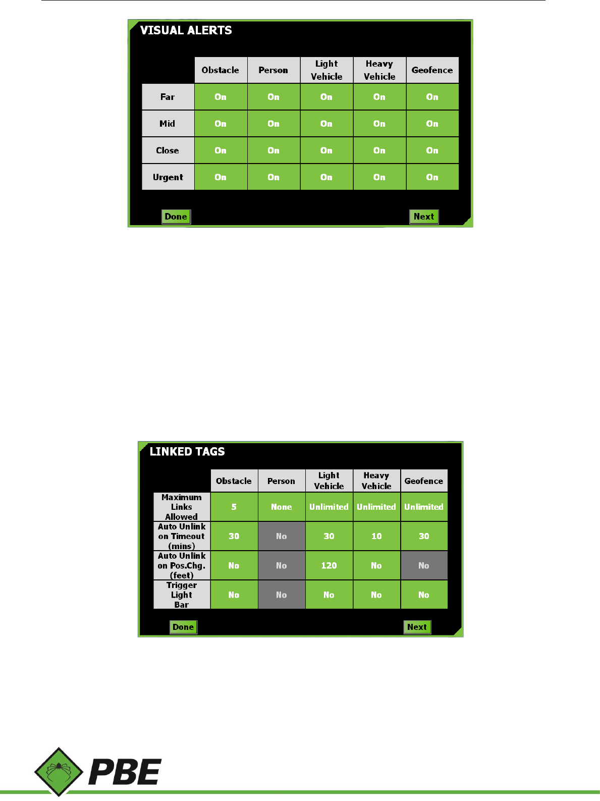
Visual Alerts
Figure 10: Visual Alerts menu screen
Select whether the light bar is on or off for each object type and zone. The light bar is:
off when no objects are detected
white when an object is detected in the Far zone
yellow when an object is detected in the Mid zone
red when an object is detected in the Close zone
flashes red when an object is detected in the Urgent zone
flashes red twice as fast when the caution alarm is sounding.
Linked Tags
Figure 11: Linked Tags menu screen
If a driver is aware of a particular object that comes into range regularly, the object can be linked with his or her vehicle,
inhibiting its audible and visual warnings, thereby reducing nuisance alarms. A tag can be linked by double-tapping on
the object’s entry in the tag list on the PAS screen. Double-tapping it again unlinks it. It will be unlinked automatically
under certain conditions described below.
Model PAS Proximity Alert System Manual Page 11 of 25
Tap on each field to toggle through the available options.
Maximum Links Allowed toggles from ‘None’ to 9, then ‘Unlimited’. If ‘None’ is selected then the driver cannot
Link to that particular type of tag, and the values of the other options below are greyed out and cannot be
adjusted. This option can be used to limit misuse of the linking feature by enforcing an optional upper limit on
the number of tags that the driver is allowed to link.
Auto-Unlink on Timeout (mins) toggles from ‘Never’ to 120, in increments of 10 minutes. This is the maximum
time that the linked tag can be absent from the PAS screen for without causing an automatic unlink. As long
as the linked tag continues to re-appear on the PAS screen at least once within this time setting, it will remain
linked (notwithstanding other unlink mechanisms). This behavior is disabled if set to ‘Never’.
Auto-Unlink on Position Change toggles from ‘No’ (disabled) to 300 ft in 60 ft increments, or in metric from
No to 100 m in 20 m increments. At the time an object is linked, its GPS position is recorded. If it moves from
that location by more than the value of this setting then it will be automatically unlinked. This behavior is
disabled if set to ‘No’. This feature requires GPS. This feature is not applicable to geofences-as-tags.
Trigger Light Bar toggles ‘Yes’ or ‘No’. If ‘Yes’ is selected, Linked objects can still create light-bar warnings when
they come into range. Regardless of this setting, audible warnings are always suppressed for linked tags.
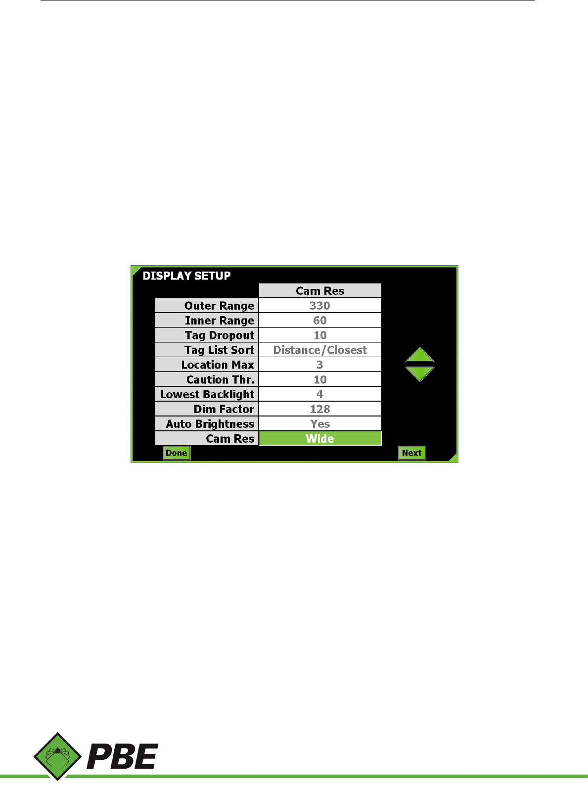
PAS Display Setup
Figure 12: Display Setup menu screen
Select an option and use the up and down arrows to select the desired value.
Outer Range defines the coverage of the zoomed-out PAS screen. Allowable values are from 100 to 600 feet or 30 to
183 metres.
Inner Range defines the coverage of the zoomed-in PAS screen. This cannot be more than the Outer Range and not less
than 10 feet or 3 metres. It is intended and highly recommended that this be set to the coverage distance of the
electromagnetic transceivers (approx. 30 feet or 9 metres).
Tag Dropout is the number of seconds an object remains on the PAS screen after its last known detection.
Tag List Sort defines the order in which the objects are presented in the Tag List on the PAS screen. They can be sorted
by distance with either the closest or farthest on top, or they can be ordered by their appearance time with either the
newest or oldest detected tag on top.
Location Max limits the number of EM transceivers used to pinpoint a tag.
Caution Threshold - When more than this many tags (not including geofences-as-tags) are detected, the caution alarm
sounds.
Model PAS Proximity Alert System Manual Page 12 of 25
Lowest Backlight defines the brightness of the display when the lowest brightness level is selected, either by the user
pressing the front-panel brightness buttons or automatically when auto-brightness is enabled. Three percent is the
lowest possible setting because zero, one and two are not sufficient to turn the backlight on. On some units screen
flicker may be observed at the lowest setting. If this is too annoying, use the next highest setting and rely more on the
Dim Factor.
Dim Factor is a number from 32 to 255 which further dims the display. This is a software feature which works in
conjunction with the hardware brightness control. It is only used when the lowest brightness level is selected. 255 means
software dimming is disabled. 32 is maximum software dimming.
Auto Brightness, when enabled, uses the PAS-100’s light sensor to automatically select the brightness of the display.
One of three levels is chosen; low, medium or high. Low is intended for underground use and sets the screen brightness
to the lowest possible setting (defined by Lowest Backlight and Dim Factor). Medium level is about 50% brightness. The
high level is the display’s maximum possible brightness. The front panel’s manual brightness controls still work when
auto-brightness is enabled but automatic levels will still be applied based on light sensor readings. Turn auto-brightness
off to rely solely on the hardware brightness buttons.
Cam Res must be set according to the aspect ratio of the camera being used. Most IP-based cameras would require the
setting be set to ‘Wide’. Analog cameras operating through an analog-to-IP converter must be set to ‘CIF’.
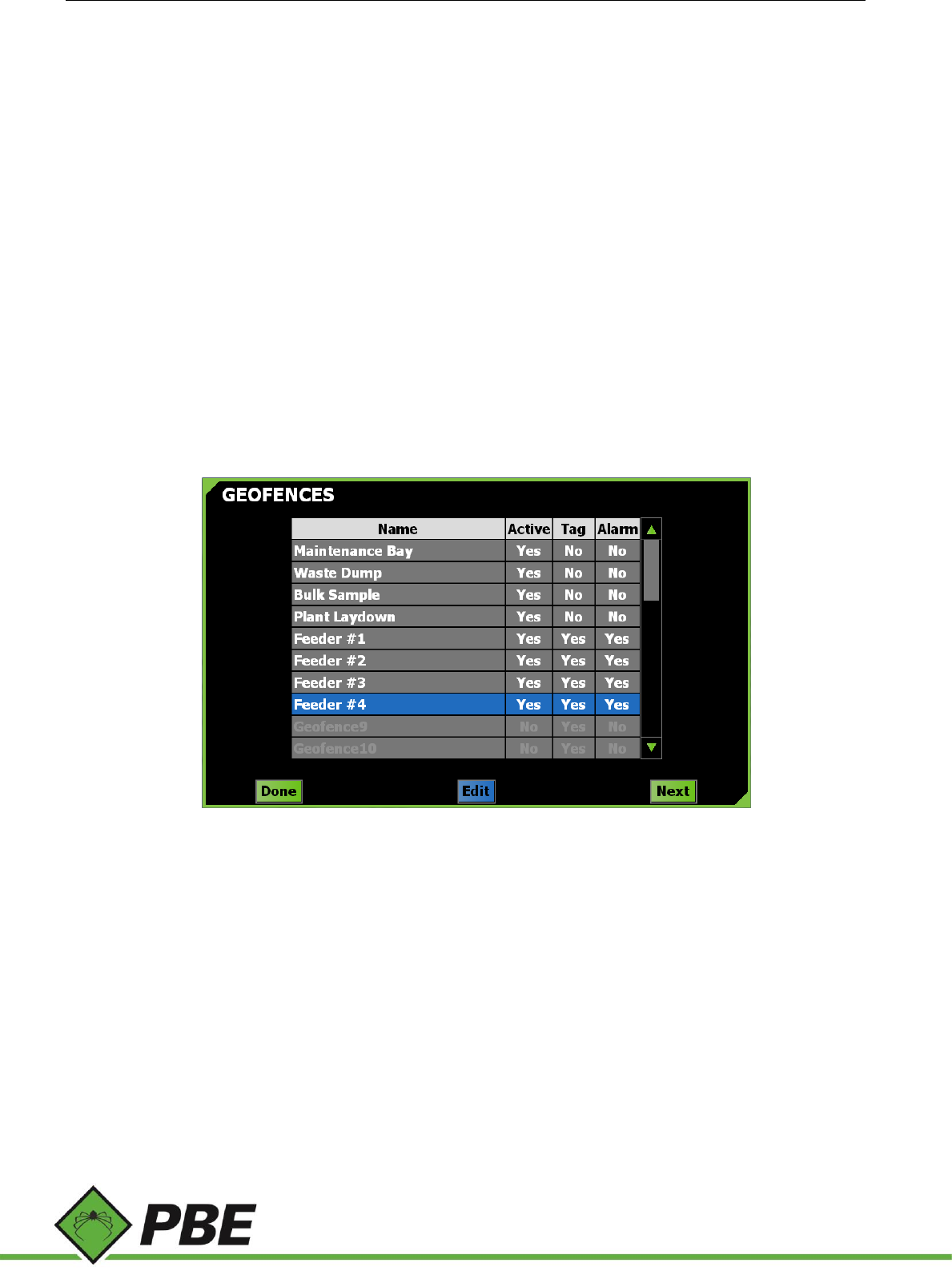
Geofences
Figure 13: Geofences menu screen
Geofencing is a virtual perimeter that can be set up by defining a polygon of latitude and longitude coordinates. As an
example, a maintenance area can be defined with a geofence and then alternative menu options can be set when driving
into this area, e.g. no warnings given - so drivers don’t get repeatedly warned each time they enter this area. Up to 32
geofences can be created. Geofencing requires GPS.
To edit a fence, single tap it and press the Edit button, or double-tap the fence’s name.
Tap in the fence’s ‘Active’ box to toggle the enabled/disabled state of the fence. The field can’t be activated if it doesn’t
have any coordinates defined.
The ‘Tag’ column specifies whether the fence is to be treated like a virtual tag or not. If set to ‘Yes’, then the closest
point of the fence is subject to audible and visual alarms, zoning and linking like any real tag. If set to ‘No’ the fence will
not appear in the tag list, but the fence’s configuration will still be applied when inside it, assuming it is Active.
The ‘Alarm’ column allows a geofence alarm to be enabled or disabled. If enabled, the alarm is sounded while the vehicle
is inside the perimeter of the geofence. Like the Urgent alarm, the geofence alarm is persistent, but can be
Model PAS Proximity Alert System Manual Page 13 of 25
acknowledged (silenced) by tapping the screen.
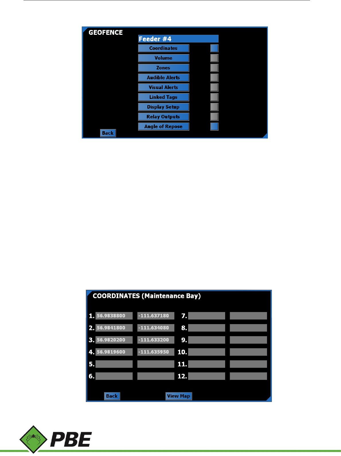
Geofence
Figure 14: Particular Geofence menu screen
This screen allows you to set the name of the geofence (up to 15 characters), its perimeter and other
configuration settings that can optionally take effect when inside the geofence.
Most geofence sub-menu screens are the same as their main-menu counterparts, but have a blue color theme
as a visual reminder that the options being set only apply when inside that geofence and are not the standard
configuration (green color theme) which applies when not inside any fence.
The push-button box beside each sub-menu defines whether that menu will, if blue, override the standard
settings when inside the geofence, or if grey, have no effect.
If the box beside the Coordinates menu is grey, the geofence will be deactivated.
Angle of Repose (more details below) is specific to geofences and has no main-menu counterpart. Its associated
push-button defines whether that feature is enabled or not.
Coordinates
Figure 15: Geofence Coordinates menu screen
Model PAS Proximity Alert System Manual Page 14 of 25
Define the geofence polygon as an ordered sequence of non-intersecting points using latitude and longitude
values in decimal degrees. Start from point one and don’t leave any gaps. The last point should not be a duplicate
of the first point.
Pressing F3 on this screen causes the vehicle’s current GPS location (if known) to be entered.
Press the View Map button to see the geofence plotted on a map.
Figure 16: Geofences (Map) menu screen example
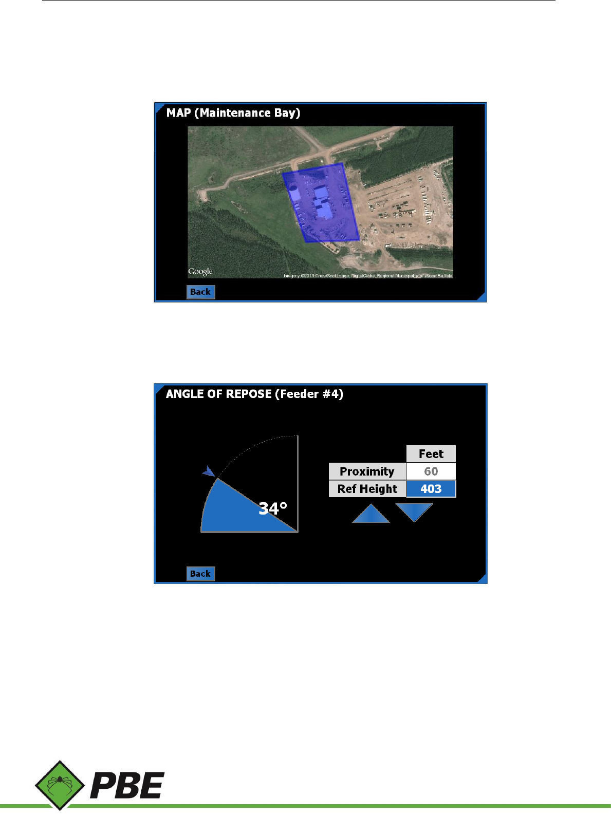
Angle of Repose
Angle of repose is intended for use on vehicles interacting with surge piles. The material on the pile is on the
verge of sliding at the angle of repose, a conservative value for which must be entered on this screen by dragging
the blue arrow.
When the vehicle is within the Proximity distance to the surge pile, PAS will increase the size of the feeder hole
(represented by the geofence perimeter) relative to how much higher the vehicle is above the Reference Height.
The Reference height is GPS height at the base of the surge pile.
If the vehicle reaches the perimeter of the inflating geofence drawn on the display, then it is at the danger point
of falling into the feeder hole if the material suddenly gives way.
As an additional safety feature, it is recommended to enable the geofence’s alarm, which will sound if the driver
Model PAS Proximity Alert System Manual Page 15 of 25
enters the danger zone (the inflated geofence)
Pressing F3 on this screen automatically fills in the Proximity and Reference Height with current GPS values.
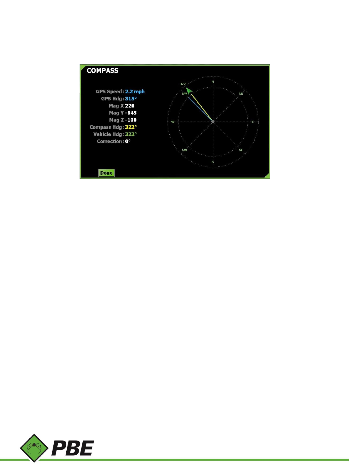
Compass
Figure 17: Compass menu screen
The purpose of the Compass setup screen is to calibrate the system’s electronic compass, which could have been
installed in any orientation.
There are eight calibration points (N, NE, E, etc.) coloured red if they aren't calibrated or green if they are.
When the GPS heading (blue needle) is within +/- 10 degrees of one of those points, a blue button appears at that point.
Press the blue button to set the current X, Y, Z magnetic field strength for that point.
After pressing the blue button, the label will change to green. Any calibrated point can be reset by right-clicking it (or
press and hold on the touch screen) and it will revert from green back to red. Pressing F2, F3 and F4 together will reset
all points.
When all eight points are green, the yellow compass needle and the draggable green needle/arrow will appear allowing
for fine tuning.
Tap and drag the green arrow until it points in the same direction as the vehicle is actually pointing, as indicated by a
trusted measurement. The compass is now calibrated.

Model PAS Proximity Alert System Manual Page 16 of 25
System
Figure 18: System menu screen
The system menu contains various sub-menus, each described below.
Detection
Figure 19: Detectability screen
The start-up equipment detection screen can be configured to ignore particular technologies which are not in use. Click
on an item to toggle its status between ‘Expect' and ‘Ignore’.
Model PAS Proximity Alert System Manual Page 17 of 25
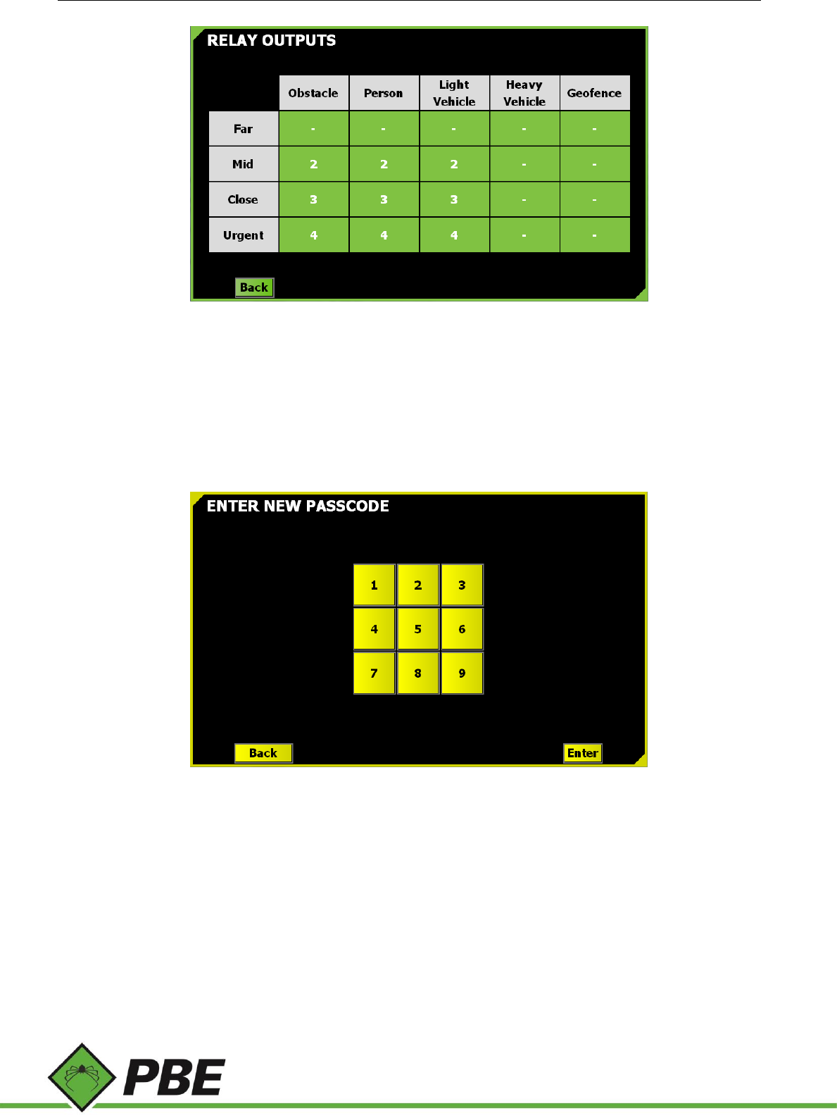
Relay Outputs
The PAS-300 Power Junction Box has isolated relay outputs which are controlled according to this screen setup. The
closest object of any given type can assert any one of four different relay outputs.
Tap any box to cycle through the five available options; 1, 2, 3, 4 and -. The dash means no relay output is asserted.
Take the above screenshot as an example setup and assume there’s an Obstacle tag in the Mid zone and a Personnel
tag in the Urgent zone. Two of the four relay outputs will be asserted; #2 (caused by the obstacle) and #4 (caused by
the person).
Passcode
The various Setup screens and Diagnostic screens (not documented - for PBE use only) can be optionally protected by a
passcode set by management to prevent modification by drivers.
The passcode is a barrier and deterrent against drivers changing the setup of the system. PBE can override and cancel
the passcode if required.
By default, there is no passcode. Create one from the Change Passcode menu. Enter up to 16 digits. It will need to be
entered a second time and if they match the passcode will be set.
The passcode can be removed by just hitting enter twice without pressing any digits on the keypad.
Note that setting a new passcode takes immediate effect. The F1 (Commit) and F5 (Discard) options used to leave setup
are not relevant to the passcode. A passcode change cannot be discarded by F5.
The Volume setup screen is, by default, the only menu not protected by the passcode, but this can be overridden by
Model PAS Proximity Alert System Manual Page 18 of 25
PBE if customers prefer it is protected too.
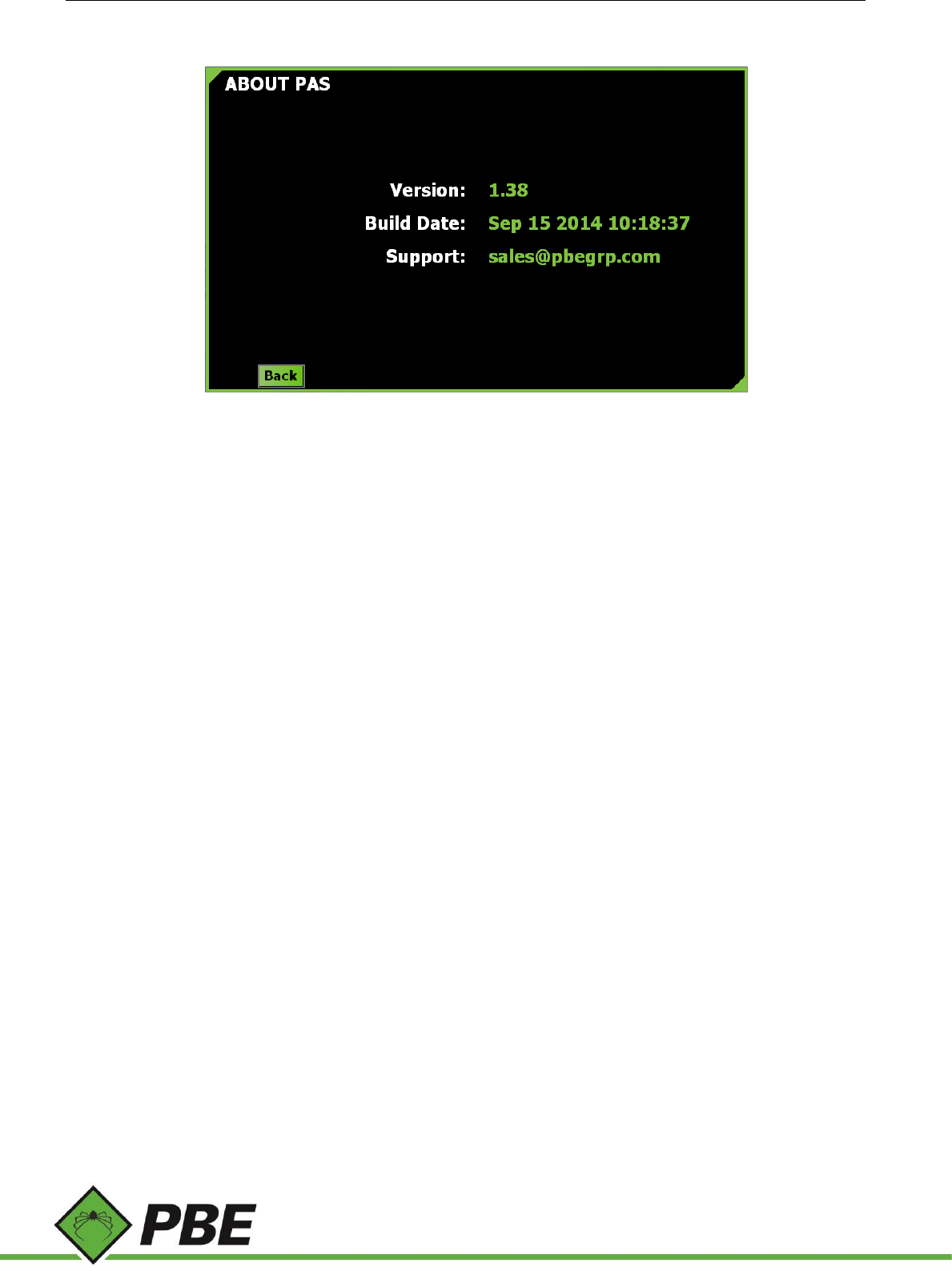
About
Figure 20: About menu screen
Displays current PAS software version and build date. Nothing can be selected on this screen.
Model PAS Proximity Alert System Manual Page 19 of 25
4. OPERATION
Local and company safety protocols and procedures should always take precedence over the warnings provided by the
PBE Proximity Alert System. The PAS warnings should be complementary to existing safety systems in place. The
Proximity Alert System will not prevent an accident on its own but will provide another level of awareness for the driver.
Switching on
The PAS-100 Controller is powered-up with the vehicle ignition.
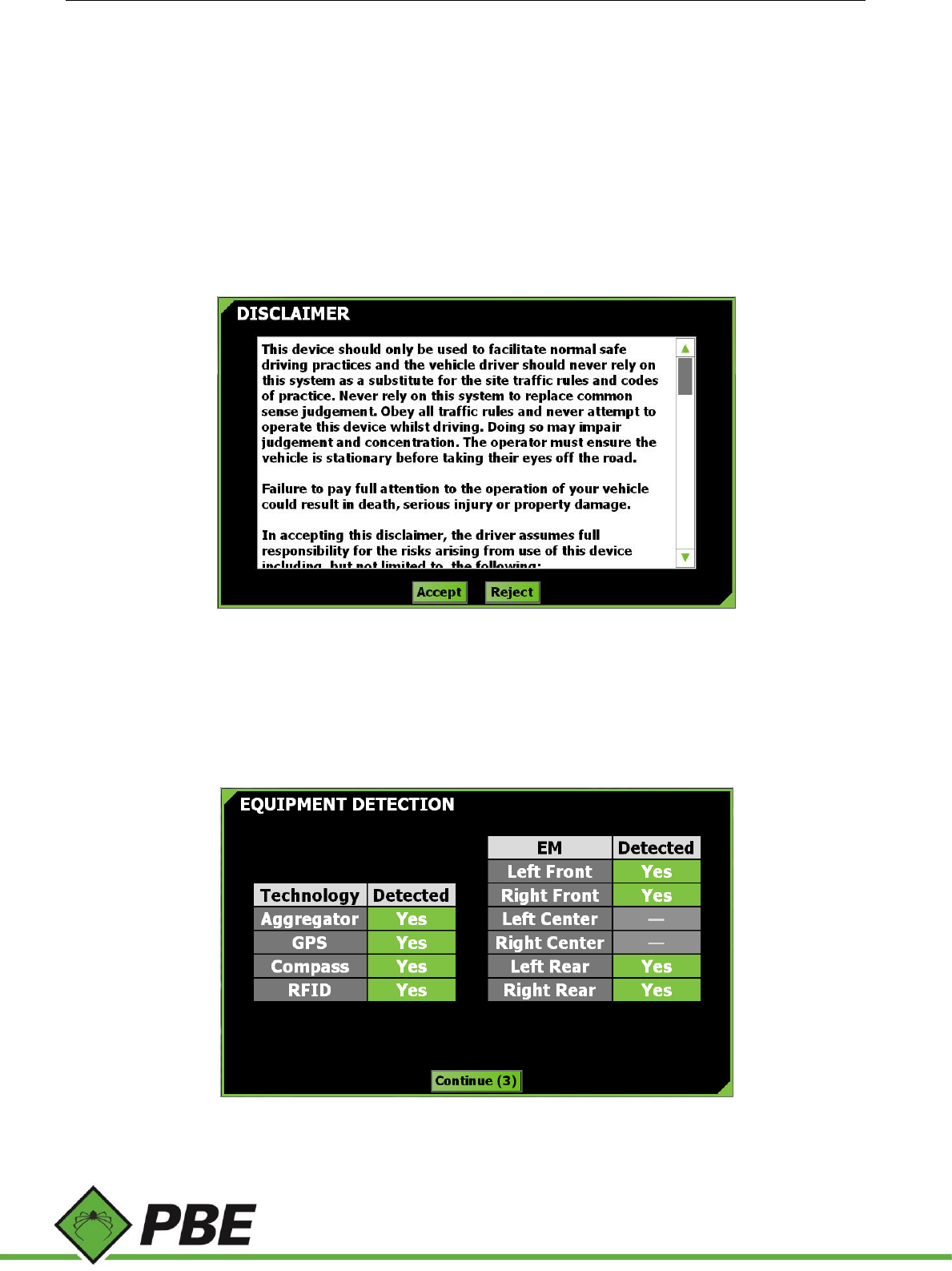
Disclaimer
Figure 21: Disclaimer menu screen
As a condition of using PAS, the disclaimer screen must be accepted. It is a reminder that the driver, not PAS, is
responsible for and in control of his or her vehicle.
Equipment Detection
Figure 22: Equipment Detection menu screen
Model PAS Proximity Alert System Manual Page 20 of 25
Before normal operation commences it must be verified that all major components of the system are functioning.
The screen will automatically dismiss itself after all equipment has been detected.
If any of the technologies show as ‘No’ in red, then maintenance is required to troubleshoot the problem.
PAS should not be relied upon if this screen has not been cleared.
For testing or troubleshooting purposes it is possible to continue operation with undetected equipment by clicking on
the red entry to acknowledge it (it will turn yellow) and agreeing to a disclaimer.
Using the Controller PAS Screen
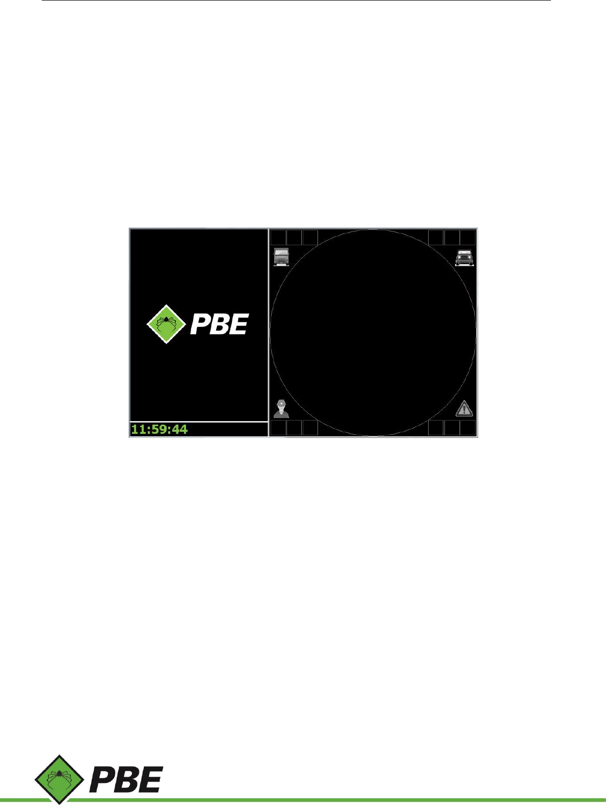
When nothing is in range, the PAS screen on the Controller shows the PBE logo on the left and the current time below
(see Figure 23). With nothing in range, the right part of the screen shows an empty black circle. The four icons represent
(clockwise from top left) Heavy Vehicle, Light Vehicle, Obstacle and Personnel.
Figure 23: PAS screen with nothing in range
PAS Screen Area Coverage
The PAS screen offers two different levels of area coverage, a zoomed-in view and a zoomed-out view.
The zoomed-out view is a black screen with a small white hub. The white hub symbolically represents the zoomed-in
coverage area (although not to scale).
The zoomed-in view is a white screen with no hub.
The triangular icon in the center of the screen is a visual cue that the vehicle is always pointing straight ahead with
respect to the PAS coverage view. It is colored green if the vehicle’s GPS position is not known or colored blue if it is.
The coverage area is quantified by a number at the base of the area which represents the distance to that boundary.
Zoomed-out Coverage View
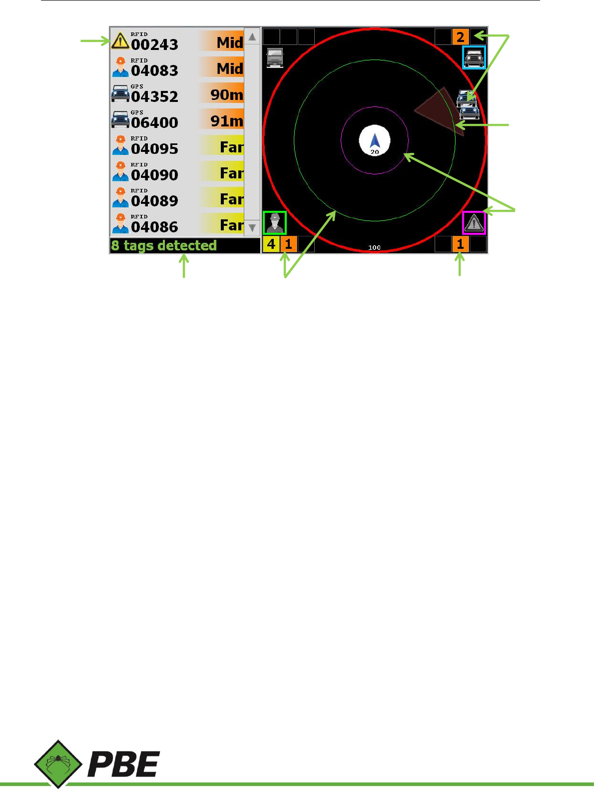
Once an object is detected its icon type and ID will appear in the list on the left (see 1 in Figure 24) with the distance it
is away from the vehicle. By default, the closest object will appear at the top of the list.
When an object comes within range, a colored square will highlight the object type (2) and the number of those objects
will be displayed in the boxes next to the icon (3 & 6). The box furthest from the center represents the number of those
objects in the Far zone (as defined in the Setup screens), the middle box represents the Mid zone, and the closest box
Model PAS Proximity Alert System Manual Page 21 of 25
the Close zone.
Figure 24: Objects on the Zoomed-out view
Figure 24 shows 8 tags (objects) detected in the Mid and Far zones. In this example the numbers represent:
1. The closest object (top of the list) is an Obstacle with an ID of ‘00243’ and it is in the Mid range as defined by
the user.
2. This Obstacle is also depicted on the bottom right of the PAS screen highlighted in purple and with a purple
ring is shown on the screen within the Mid zone. As this Obstacle is detected by RFID it is shown as a ring.
3. As this obstacle is within the Mid zone, the number of these objects is shown in the central orange box.
4. Two Light Vehicles are detected; both in the Mid zone and shown as icons as they are detected by GPS.
5. The brown region shows a user defined geofence.
6. There are 5 Personnel tags detected; 4 outside the current Mid zone screen (portrayed by the red outer ring)
and one in the Mid zone depicted by the green circle
7. The status or notification bar shows messages and current time (see Notifications below).
1
2
3
4
6
7
5
Model PAS Proximity Alert System Manual Page 22 of 25
Zoomed-in Coverage View
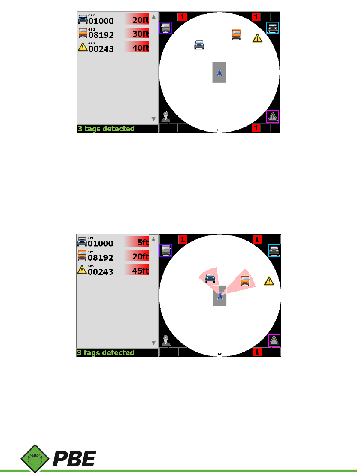
Figure 25: Objects on the Zoomed-in view
Figure 25 shows three tagged objects detected in the Close Zone.
Note the grey box containing the blue arrow. This box represents the outline of the vehicle and is drawn to scale based
on the vehicle dimensions entered in a setup screen.
The tag distances in the tag list are usually to the outline of the vehicle. In some cases, if there is insufficient information,
the distance may be reported to the center of the vehicle.
Urgent Alarm
Figure 26: Objects in Urgent Zone
When objects enter the Urgent zone, the driver is alerted in several ways; an alarm is sounded, the objects are
highlighted with a red sector and the light bar is flashed.
The driver can acknowledge (silence) the alarm by touching anywhere inside the coverage area of the PAS screen.
However, the alarm cannot be silenced if there are personnel in the urgent zone.
Figure 26 shows three tagged objects detected in the Close zone, two of which are within the urgent zone (represented
by the red sectors).
Model PAS Proximity Alert System Manual Page 23 of 25
Caution Alarm
A caution alarm may sound when the number of detected tags increases beyond a threshold in order to warn the driver
that system accuracy and responsiveness may be adversely affected. The operator may acknowledge (silence) the alarm
by touching anywhere inside the coverage area of the PAS screen.
Geofence Alarm
A geofence alarm may sound if inside the perimeter of a geofence which has the alarm enabled. The operator may
acknowledge (silence) the alarm by touching anywhere inside the coverage area of the PAS screen.
Video
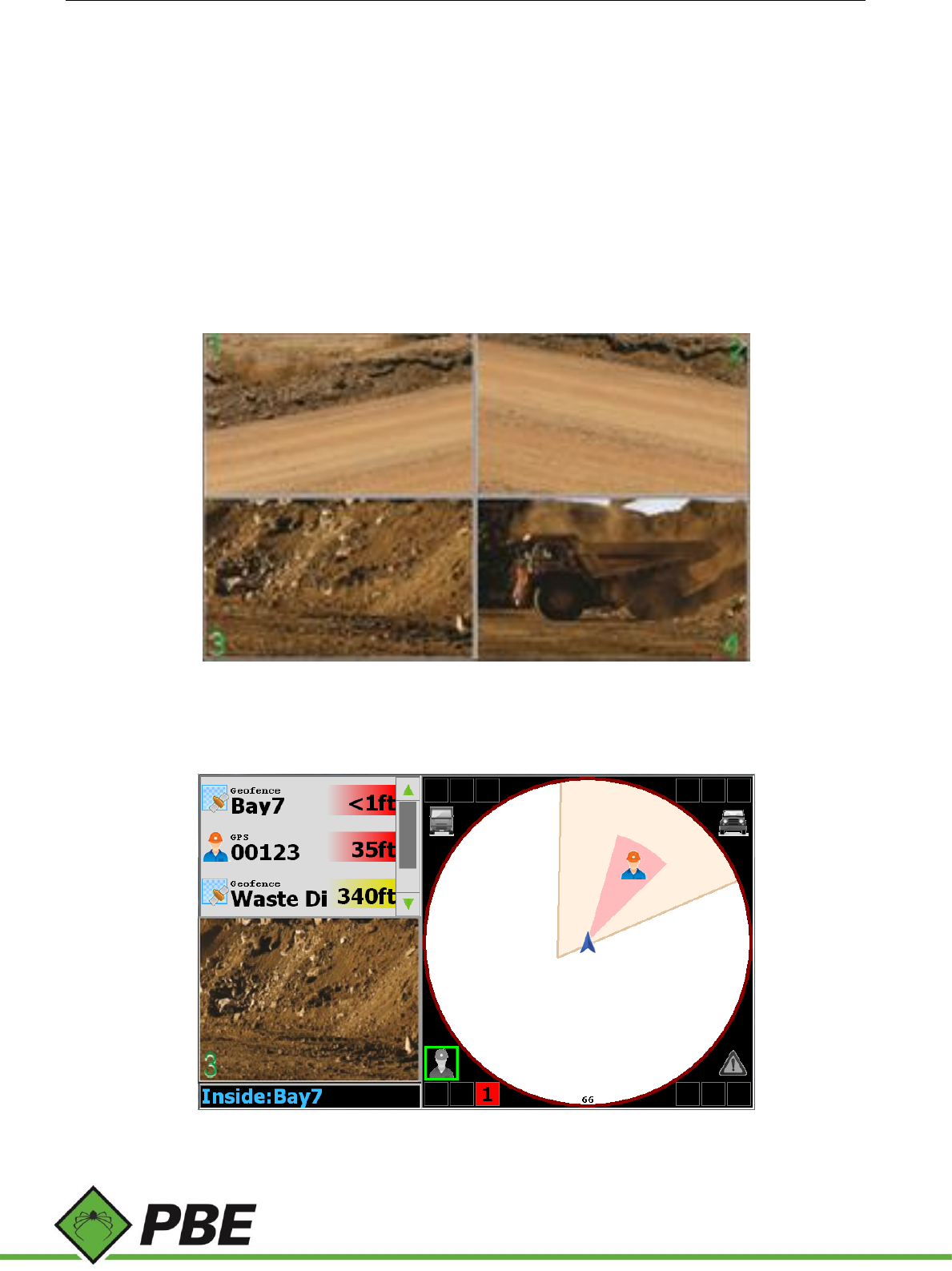
If optional IP cameras are installed, live video streams can be viewed from within the application.
Figure 27: Video screen showing all 4 cameras available
Press F5 to view up to 4 IP camera feeds simultaneously. Click/touch a panel to make it full screen and again to return
to the multi-camera view.
Figure 28: Toggled to only show one video display

Model PAS Proximity Alert System Manual Page 24 of 25
On the main PAS screen, press F4 to cycle through side panel modes. The three available modes are:
a) Full tag list (no video)
b) Mini tag list with one IP camera view (depicted above)
c) No tag list, two IP camera views.
Click on a camera window to cycle through the available cameras.
In addition to IP cameras, one analog camera is supported. But only one type or the other may be used, not both. If
there are no IP cameras detected, then pressing F5 will display the analog camera feed. The analog camera is only shown
full screen and can’t be displayed in the side panel.
Vehicle Occupants
To suppress the tags worn by the driver and any other occupants of the vehicle, select the tag in the tag list (highlighted
with a green border) and press F3. Repeat for any other occupants.
Press F3 with no tags selected to restore all occupant tags to the list. If a tag leaves its own vehicle’s coverage area, it
will automatically lose occupant status.
Notifications
Notifications appear on the Controller’s main PAS screen (see 7 in Figure 24). Some of the notifications include:
Time of Day = the current time is shown when there are no tags detected
Tags Detected = total number of tags detected
Changes Saved = setup menu changes saved (using F1)
Data Connection Lost = Communication between the Controller and the Aggregator has been lost. Check connections.
Connection restored = Communication between the Controller and the Aggregator has been restored.
Faulty Sensors = Lists the sensor(s) that require service. LF = Left Front; RF = Right Front; LC = Left Center; RC = Right
Center; LR = Left Rear; RR = Right Rear
Overloaded Sensors = Lists the sensor(s) that require service. (see above)
Inside: [Geofence name] = Lists the name of the geofence the vehicle has entered.
Exited: [Geofence name] = Lists the name of the geofence the vehicle has exited.
CAUTION: Many tags = There are a high enough number of tags detected that the accuracy and responsiveness of the
system could be adversely affected.
Other Features
Event Log
Automated event log recording.
Maintenance
Never open any PAS equipment. For safety reasons, the equipment should be opened only by qualified service
personnel.

Model PAS Proximity Alert System Manual Page 25 of 25
Cleaning: Use a damp cloth. Do not use liquid or spray detergents for cleaning.
Storage: -30° C (-22° F) to 60° C (140° F)
Operating temperature: Do not operate over 50° C (122° F)
FCC COMPLIANCE STATEMENT
CAUTION: Changes or modifications not expressly approved could void your authority to use this equipment
This device complies with Part 15 of the FCC Rules. Operation to the following two conditions: (1) This device may not
cause harmful interference, and (2) this device must accept any interference received, including interference that may
cause undesired operation
INDUSTRY CANADA STATEMENT
This device complies with Industry Canada licence-exempt RSS standard(s). Operation is subject to the following two
conditions: (1) this device may not cause interference, and (2) this device must accept any interference, including
interference that may cause undesired operation of the device.
Le présent appareil est conforme aux CNR d'Industrie Canada applicables aux appareils radio exempts de licence.
L'exploitation est autorisée aux deux conditions suivantes : (1) l'appareil ne doit pas produire de brouillage, et (2)
l'utilisateur de l'appareil doit accepter tout brouillage radioélectrique subi, même si le brouillage est susceptible d'en
compromettre le fonctionnement.