Pyramid Communications SVR-200LA 29-50MHz LOW BAND TRANSCEIVER User Manual SVR 200LA Service Manual pmd
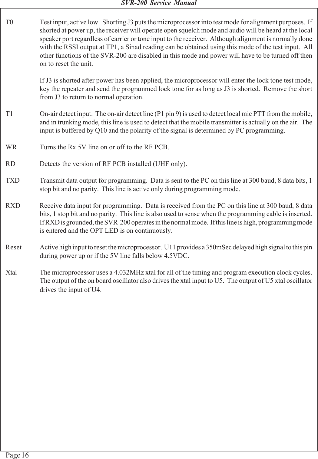
Pyramid Communications 29-50MHz LOW BAND TRANSCEIVER SVR 200LA Service Manual pmd
UserManual.wiki
>
Pyramid Communications
>
SVR 200LA User Manual
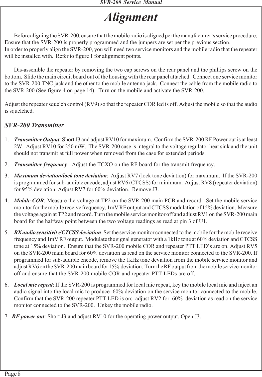
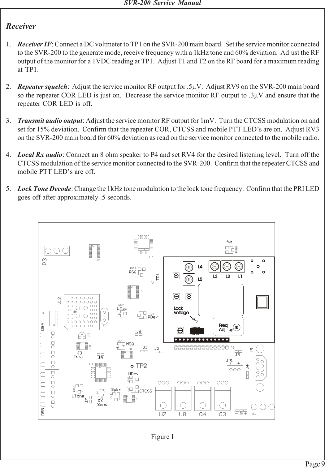
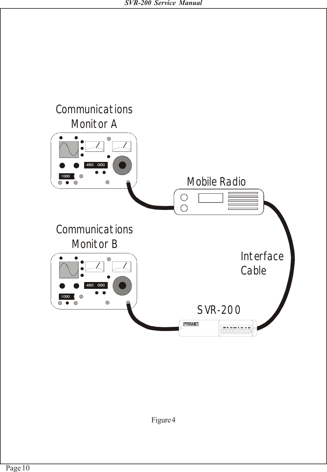
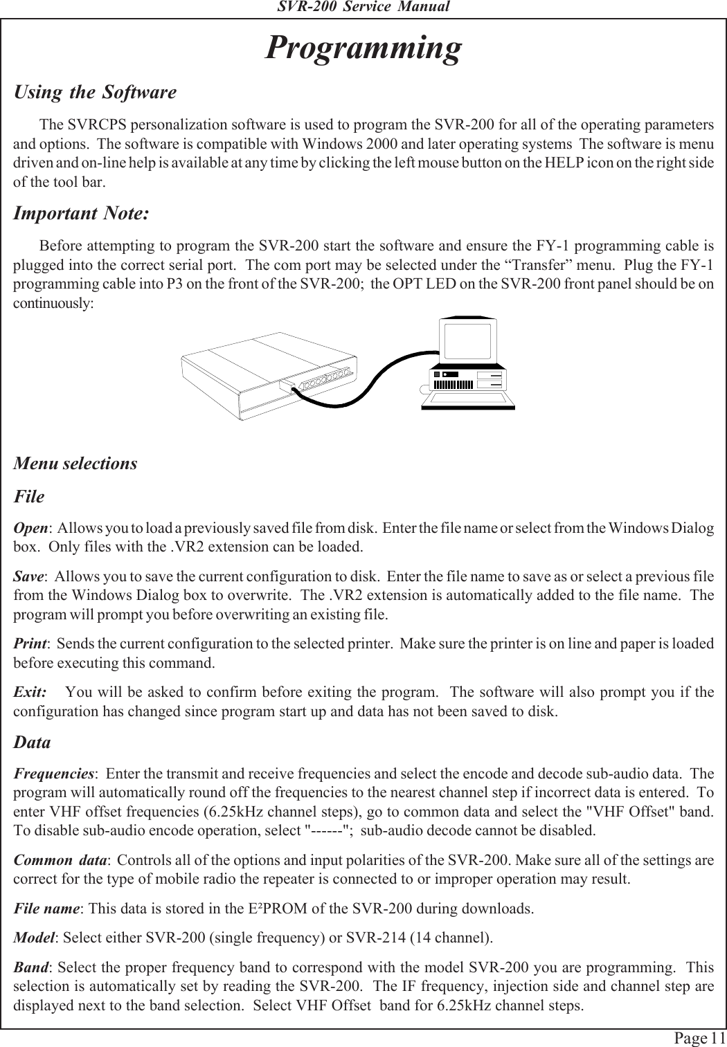
USERS MANUAL
Navigation menu
Upload a User Manual
Namespaces
Wiki Guide
HTML
PDF
Info
Views
User Manual
Discussion / Help
Navigation