Pyramid Communications SVR-200M LOW POWER VEHICULAR REPEATER User Manual SVR MAN
Pyramid Communications LOW POWER VEHICULAR REPEATER SVR MAN
UserManual.wiki
>
Pyramid Communications
>
SVR 200M User Manual
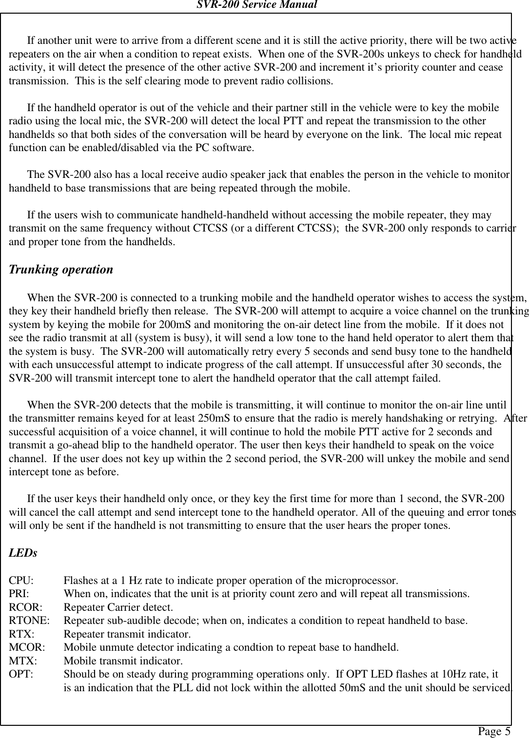
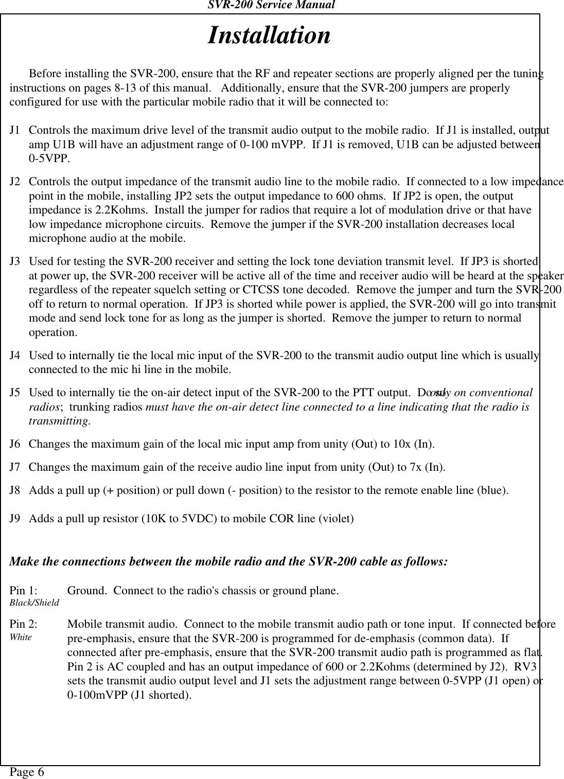
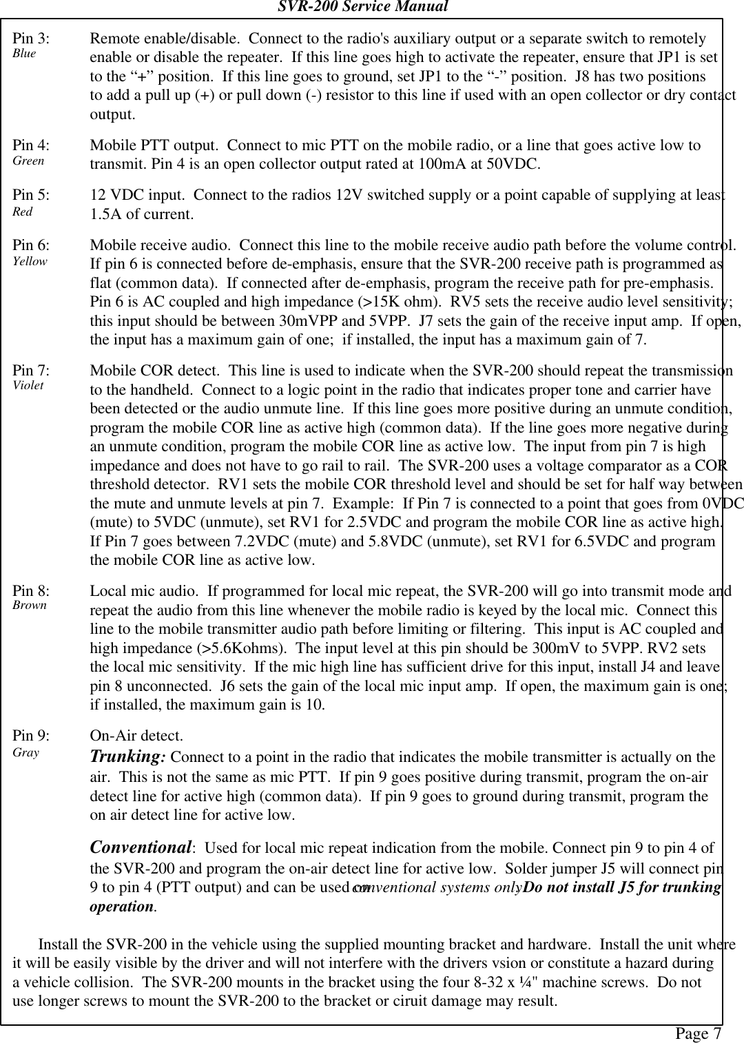
USERS MANUAL
Navigation menu
Upload a User Manual
Namespaces
Wiki Guide
HTML
PDF
Info
Views
User Manual
Discussion / Help
Navigation