Pyramid Communications SVR-250U Vehicular Repeater User Manual SVR 250 Service Manual pmd
Pyramid Communications Vehicular Repeater SVR 250 Service Manual pmd
Users Manual

Page 1
SVR-250 Service Manual
Table of Contents
Foreword ............................................................................................................................................... 2
Specifications........................................................................................................................................ 3
Functional Description.......................................................................................................................... 4
Multi-Vehicle Format ........................................................................................................................... 4
ESP Priority Format .............................................................................................................................. 5
Local Mic Repeat .................................................................................................................................. 5
Trunking Operation .............................................................................................................................. 5
Emergency Operation ........................................................................................................................... 6
Dual Tone Operation ............................................................................................................................ 6
Auxiliary Receiver Operation ............................................................................................................... 6
WideBand/NarrowBand Channels ........................................................................................................ 7
Courtesy Beep ....................................................................................................................................... 7
Power Up Channel ................................................................................................................................ 7
Full Duplex Operation .......................................................................................................................... 7
LED Indicators ...................................................................................................................................... 7
Installation ............................................................................................................................................ 8
Jumpers ................................................................................................................................................. 8
Main Connector .................................................................................................................................... 8
VHF Transmitter Alignment............................................................................................................... 10
VHF Receiver Alignment ................................................................................................................... 11
UHF Transmitter Alignment............................................................................................................... 12
UHF Receiver Alignment ................................................................................................................... 13
700/800/900MHz Transmitter Alignment .......................................................................................... 14
700/800/900MHz Receiver Alignment...............................................................................................15
Programming ...................................................................................................................................... 17
Common Data ..................................................................................................................................... 18
Channel Data ...................................................................................................................................... 19
Transfer ............................................................................................................................................... 20
Remote Help ....................................................................................................................................... 20
ARS-250 Programming ...................................................................................................................... 21
Flash Programming ............................................................................................................................. 22
Theory of Operation............................................................................................................................ 24
Parts List Main PCB ........................................................................................................................... 26
Parts Locator Main PCB ..................................................................................................................... 28
Schematic Main PCB .............................................................................................................. Foldout 1
Front Panel Assembly ............................................................................................................. Foldout 2
VHF Transmitter ..................................................................................................................... Foldout 3
VHF Receiver ......................................................................................................................... Foldout 4
UHF Transmitter ..................................................................................................................... Foldout 5
UHF Receiver ......................................................................................................................... Foldout 6
700/800/900 MHz Transmitter ............................................................................................... Foldout 7
700/800/900 MHz Receiver.................................................................................................... Foldout 8

Page 2
SVR-250 Service Manual
Foreword
Scope of this manual
This manual contains the specifications, functional description, operating instructions, schematic, parts
locator and parts list for the SVR-250 synthesized vehicular repeater.
This manual is intended for use by qualified service technicians to aid them with installation, interfacing,
alignment and trouble shooting of the SVR-250 when used with other land mobile radios.
Service manual revisions
Component changes, additions and deletions may occur in the circuit design to improve operation and will
be reflected in future releases of this service manual. Specifications and circuit changes are subject to change
without prior notice or obligation by Pyramid Communications.
Safety Information
The SVR-250 is designed to operate within all applicable Federal regulations at the time of manufacture. Proper
operation and service procedures will assure continued compliance with these regulations:
• Do not operate the SVR-250 without an antenna or appropriate RF load connected to the antenna connector.
• Do not operate the SVR-250 in the presence of unshielded electrical blasting caps or explosive environmental
conditions.
• Do not operate the SVR-250 while refueling the vehicle or in the presence of explosive fumes.
• Do not operate the SVR-250 with persons standing closer than 2 feet from the mobile or repeater antenna.
FCC information
The SVR-250 complies with the FCC rules parts 90 and 22 for radio frequency transmitters. The user must apply
for a license to operate the SVR-250 transmitter pursuant to parts 90.243 and 90.247. Other FCC rules may apply
depending on the class of service the user qualifies for. A complete listing of FCC rules and regulations may be
ordered from:
Superintendent of Documents
Government printing office
Washington DC 20402
The following information pertaining to the SVR-250 should be included in the FCC license application:
VHF UHF 700/800/900 MHz
Type Acceptance: LRUSVR-200VB LRUSVR-200U LRUSVR-200M
Output Power: 0.25-2.0W 0.25-2.0W 100mW-600mW
Emission designator: 11K0F3E/16K0F3E 11K0F3E/16K0F3E 11K0F3E/16K0F3E
Frequency band: 150-174 MHz 400-512MHz 764-806(700M), 806-824 or 850-870(800M)
897-902 or 936-941 (900M)
Number of Channels: 20 20 20

Page 3
SVR-250 Service Manual
Specifications
Transmitter:VHF UHF 700/800/900 MHz
Frequency Range: 150-174 MHz 405-425 MHz (UA)1764-776, 794-806 (MC,MD)
450-470 MHz (UD) 806-824, 850-870 (MB,MA)
470-490 MHz (UE)1897-902, 936-941 (ME,MF)
Rf power out: 250mW - 2W 250mW - 2W 100mW - 600mW
Spurious emissions: -50dBc -50 dBc -50dBc
Freq stability -30°~+60°C: 1.5 PPM 1.5 PPM 1.5 PPM
Modulation: 16K0F3E /11K0F3E 16K0F3E /11K0F3E 16K0F3E2/11K0F3E
Hum and Noise: -40/-37dB (25/12.5kHz) -40/-37dB (25/12.5kHz) -40/-37dB (25/12.5kHz)
Audio response (300-3kHz): Flat or +6dB/octave Flat or +6dB/octave Flat or +6dB/octave
Audio distortion: <3% @ 60% deviation <3% @ 60% deviation <3% @ 60% deviation
Local mic sensitivity: 300mV-5VPP 300mV-5VPP 300mV-5VPP
FCC Type Acceptance: LRUSVR-200VB LRUSVR-200U LRUSVR-200M
Industry Canada Approval: 2390 195 458A 2390 212 113A 2390A-SVR200M
Receiver:
Frequency Range: 150-174 MHz 405-425 MHz (UA)1764-776, 794-806 (MC,MD)
450-470 MHz (UD) 806-824, 850-870 (MB,MA)
470-490 MHz (UE)1897-902, 936-941 (ME,MF)
RF sensitivity: .35μV .35μV .35μV
Squelch sensitivity: .2μV to 2μV adjustable .2μV to 2μV adjustable .2μV to 2μV adjustable
Modulation acceptance: ±7.5 /±3.75kHz ±7.5 /±3.75kHz ±7.52 /±3.75kHz
Selectivity: 60/57dB (25/12.5 kHz) 60/57dB (25/12.5 kHz) 50dB
Spurious/image rejection: 60db 60db 60db
IMD response: 60db 60db 60db
Frequency stability: 1.5 PPM 1.5 PPM 1.5 PPM
Audio response (300-3kHz): Flat or -6db/octave Flat or -6db/octave Flat or -6db/octave
Audio output: 0-5VPP AC coupled 0-5VPP AC coupled 0-5VPP AC coupled
Local Rx Audio: 400 mW 8 Ohms 400 mW 8 Ohms 400 mW 8 Ohms
Power Requirements:
DC Supply 13.6 VDC 13.6VDC 13.6VDC
Standby 170 mA 170mA 170mA
Receive 250 mA 250mA 250mA
Transmit 1 A @ 2W 1.5A @ 2W 700mA @ 600mW
Physical:
Dimensions: 5.75"W x 8"L x 2.25"H
Weight: 36 oz.
Case: One piece extruded aluminium
1405-425 and 470-490 available as special order Only
216K0F3E & ±7.5kHz available on 806-824 and 850-870 MHz Only

Page 4
SVR-250 Service Manual
Functional Description
Generally, vehicular repeaters are used as mobile extenders in cross-band operation: the link is VHF/UHF/800
MHz simplex and the mobile is Lo-band, VHF, UHF or trunking. In-band operation is possible, but care must be
taken to prevent interference between the mobile's higher power transmitter and the repeater receiver. Proper
frequency selection and antenna placement are important even in cross-band operation, but especially for inband
use. Low power pre-selector cavities may be placed in line with the repeater antenna cable since it is simplex and
low power.
Important Note
The SVR-250 is designed to operate on simplex frequencies; part of the multi-vehicle format dictates that
all of the SVR-250s must be able to monitor all link traffic on site and be able to determine if a handheld is
transmitting, or if other repeaters are transmitting. The handhelds must transmit CTCSS, but should be carrier
squelch receive. The handhelds should not use CTCSS decode if the repeater is utilizing the multi-vehicle
format, as this will interfere with the priority sampling which is essential for multi-vehicle operation. Also, the
handhelds would have to have different encode and decode tones in order for the repeater to be able to tell the
difference between handhelds and other repeaters, so the handhelds would not be able to hear each other. The
repeaters should not transmit CTCSS unless used only in a single vehicle environment.
When the user leaves the vehicle, they activate the SVR-250 via their mobile radio front panel or a separate
switch. When the mobile radio is receiving carrier and proper tone, the SVR-250 will begin transmitting on the
handheld’s receive frequency. The user is able to hear and respond to all radio traffic, including other handhelds
at the site. The SVR-250 can be programmed to give the handhelds priority in a conversation by periodically
sampling for handheld activity (carrier and proper tone) during base-to-portable transmissions. During sampling,
if the SVR-250 detects a handheld transmission, it will cease transmissions, key the mobile radio and repeat
portable-to-base. This allows the handheld to respond during repeater hang time or during full duplex interconnect
calls. Priority sampling can be enabled/disabled through PC programming and the interval can be programmed
between .25 seconds and 2.5 seconds in .25 second increments.
The SVR-250 has a programmable time out timer for base-to-portable transmissions. If the mobile COR is
active for more than the programmed time (and the SVR-250 is the priority unit) it will send a double blip and cease
transmission until the mobile COR is inactive. The time-out is in affect regardless of whether the SVR-250 is
programmed for priority sampling or not.
Multi-vehicle operation
The SVR-250 has 2 different multi-vehicle priority formats; both are compatible with the existing SVR-200
and Motorola PAC/RT formats. The new SVR-250 with ESPTM logic has enhanced features that ensures a priority
vehicle is selected and ready to transmit during the idle time rather than during voice transmissions. The 2 formats
are explained below:
SVR-200 Legacy format
When the SVR-250 is first activated, it will transmit a short “lock tone” that alerts the user that the system
is functioning. It will then assume the priority status and be ready to repeat any base-to-portable or portable-to-
base transmissions. If another unit arrives on scene and is activated, it too will transmit the “lock tone”; when
the first SVR-250 detects the lock tone from the second unit, it will increment a “priority counter” and will no
longer repeat any transmissions. The recently arrived unit will be the priority repeater, and the first unit will be
1 count away from priority. This process will continue for each unit that arrives at the site, creating a priority
hierarchy for up to 256 vehicles, each with a unique count and only one unit at priority status. The SVR-250 will
not transmit its lock tone if the radio channel is busy when first enabled. It will wait in non-priority status until
all transmissions cease, then send its lock tone and become the priority unit.
)

Page 5
SVR-250 Service Manual
Even though the other SVR-250s are not at priority status, they will continue to monitor the channel for
activity. If the priority unit were to leave the scene or become disabled, the other units will detect the condition
to repeat and determine that there is no priority unit repeating the transmission. They will then begin to decrement
their priority counters until one of them reaches the priority status and begins repeating the transmission. Since
the SVR-250s are all at different counts, only one will reach priority status and begin transmitting. The other
units will sense the new priority repeater and cease counting down, preserving the priority hierarchy.
If another unit were to arrive from a different scene and it is still the active priority, there will be two active
repeaters on the air when a condition to repeat exists. When one of the SVR-250s unkeys to check for handheld
activity, it will detect the presence of the other active SVR-250 and increment its priority counter and cease
transmission. This is the self clearing mode to prevent radio collisions.
ESPTM Priority
The SVR-250 Enhanced Sensor Priority works similar to the SVR-200 and PAC/RT formats and is completely
backward compatible with those systems. The SVR-250 determines if there is a priority (and re-establishes the
priority if missing) during idle time between conversations rather than at the critical start of a conversation. When
a condition to repeat exists, the SVR-250 is always ready.
The priority SVR-250 will transmit a short tone burst every 10 seconds. This serves 2 purposes: It informs
the handheld operator that they are still within range of the vehicle and it alerts the non-priority units that a priority
vehicle is still on scene. As long as the non-priority units hear this "beacon" every 10 seconds, they preserve their
counts and maintain the priority hierarchy. If the priority vehicle leaves the scene, after 10 seconds, the non-
priority vehicles will not hear the "beacon" and begin counting down. When one of the counts=0, that SVR-250
will send lock tone for 800 mS, assume priority and begin sending the "beacon" tone every 10 seconds as before.
Since the "beacon" tone must be heard every 10 seconds, it does not have busy carrier lock out and will send the
tone if 2 handhelds are communicating directly or in the presence of co-channel interference.
Local Mic Repeat
If the handheld operator is out of the vehicle and their partner still in the vehicle were to key the mobile radio
using the local mic, the SVR-250 will detect the local PTT and repeat the transmission to the other handhelds so
that both sides of the conversation will be heard by everyone on the link. The local mic repeat function can be
enabled/disabled via the PC software.
The SVR-250 also has a local receive audio speaker jack that enables the person in the vehicle to monitor
portable-to-base transmissions that are being repeated through the mobile.
If the users wish to communicate portable-to-portable without accessing the mobile repeater, they may
transmit on the same frequency without CTCSS (or a different CTCSS); the SVR-250 only responds to carrier
and proper tone from the handhelds.
Trunking operation
When the SVR-250 is connected to a trunking mobile and the handheld operator wishes to access the system,
they key their handheld briefly then release. The SVR-250 will attempt to acquire a voice channel on the trunking
system by keying the mobile for 800mS and monitoring the on-air detect line from the mobile. If it does not see
the radio transmit at all (system is busy), it will send a low tone to the hand held operator to alert them that the
system is busy. The SVR-250 will automatically retry every 5 seconds and send busy tone to the handheld with
each unsuccessful attempt to indicate progress of the call attempt. If unsuccessful after 30 seconds, the SVR-250
will transmit intercept tone to alert the handheld operator that the call attempt failed.

Page 6
SVR-250 Service Manual
When the SVR-250 detects that the mobile is transmitting, it will continue to monitor the on-air line until the
transmitter remains keyed for at least 250mS to ensure that the radio is not handshaking or retrying. After
successful acquisition of a voice channel, it will continue to hold the mobile PTT active for 2 seconds and transmit
a go-ahead blip to the handheld operator. The user then keys their handheld to speak on the voice channel. If the
user does not key up within the 2 second period, the SVR-250 will unkey the mobile and send intercept tone as
before.
If the user keys their handheld only once, or they key the first time for more than 1 second, the SVR-250 will
cancel the call attempt and send intercept tone to the handheld operator. All of the queuing and error tones will
only be sent if the handheld is not transmitting to ensure that the user hears the proper tones.
The SVR-250 can also be programmed to work in a similar way for use with the MSV mobile satellite phones,
except the time delays are extended to work properly within the network.
Emergency Operation
The SVR-250 can be programmed for Emergency operation on a per channel basis. If enabled, the SVR-250
will scan for 2 different CTCSS tones or DCS codes. The secondary tone/code is used to indicate an Emergency
condition from the portable and will assert an output pin when decoded. There are 2 different Emergency formats:
Emg output only or Emg output with voice repeat. Emg output only will assert pin 10 on the main cable for as
long as the secondary tone/code is being received; it is used as a momentary output to the mobile to initiate an
Emergency sequence. This is the most common configuration with Motorola or MA/Com radios. Emg output
with voice repeat will assert pin 10 as before, but will also key the mobile and repeat portable-to-base as long as
the secondary tone/code is being received. This format is used with the Tait mobiles. Additionally, there is a solder
jumper on the main logic PCB that determines if the Emg output signal pulls to ground (NO) or breaks ground
(NC).
Dual Tone Operation
The SVR-250 normally requires its own frequency and earlier technology suffered when there was strong
co-channel interference present. The SVR-250 can be programmed for dual CTCSS/DCS receive that will
eliminate interference from co-channel users. The portable radios will still be carrier squelch receive, but the
SVR-250s will be programmed with a CTCSS/DCS encode that is different from the primary tone/code decode.
The secondary tone/code must be the same as the encode tone/code. During base-to-portable transmissions, the
SVR-250 will sample as before. If it sees carrier and primary tone, it will reverse direction and repeat portable-
to-base. If it sees secondary tone (another SVR-250 transmitting) it will cease transmission and become non-
priority. If it sees carrier with no tone (or neither programmed tone) it will ignore the co-channel interference.
If three consecutive samples have co-channel interference, the SVR-250 will change the sampling rate to 2.5S
(maximum) to reduce the effects of the extended sample time, until the co-channel signal is no longer present.
Dual Tone receive and Emergency operation are mutually exclusive.
Auxiliary Receiver Operation
In operations where the vehicles do not transmit mobile-to-mobile (half duplex), the non-priority vehicular
repeaters will not see mobile COR when a priority vehicular repeater keys its mobile during portable-to-base
transmissions. This can cause the non-priority repeaters to incorrectly assume priority. The SVR-250 can be fitted
with an additional 16 channel scanning receiver that is programmed for the mobile transmit frequency. This
Auxiliary receiver can have up to 16 mobile transmit frequencies programmed into it and will provide the mobile
COR indication needed for the non-priority repeaters to remain at non-priority. The Auxiliary receiver option can
be programmed to operate on a per channel basis.

Page 7
SVR-250 Service Manual
Wide Band / Narrow Band Channels
The SVR-250 can be programmed for Wide/Narrow band operation on a per channel basis. Wide band
operation is 25kHz for UHF and 800 MHz, 30kHz for VHF. Narrow band is 12.5kHz for UHF and 800 MHz,
15kHz for VHF. VHF channels can be in 5 or 6.25kHz steps on a per channel basis. UHF is programmed in
12.5kHz steps. 700/800/900 MHz are programmed in 6.25kHz steps. 700 and 900 MHz are only available as
narrow band (12.5 kHz). In addition to changing the receiver bandwidth and transmitter modulation characteristics,
the audio levels into and out of the SVR-250 are automatically adjusted so the levels at the mobile will be correct
with either bandwidth selected.
Courtesy Beep
If enabled, the SVR-250 will send a short beep to the handheld user at the end of each portable-to-base
transmission to confirm that the user is still within range.
Power Up Channel
The SVR-250 can be programmed to revert to the last channel used when powered down or a pre-programmed
"Home" Channel.
Full Duplex Operation
The SVR-250 can be configured to operate full duplex and repeat portable-to-portable during portable-to-base
transmissions, thereby extending coverage between portables as well as operating as a vehicular repeater. Full
duplex operation requires hardware and firmware changes and is not field upgradeable. Full duplex operation
is not compatible with multi-vehicle format and should only have 1 SVR-250 on scene. The SVR-250 configured
for duplex operation will have separate Tx and Rx antenna connectors and requires an external duplexer or
separate Tx and Rx antennas.
LEDs
The SVR-250 has a 2 digit channel display as well as eight status LEDs:
CPU: Flashes at a 1 Hz rate to indicate proper operation of the microprocessor.
PRI: When on, indicates that the unit is at priority count zero and will repeat all transmissions.
RCOR: Repeater Carrier detect.
RTONE: Repeater sub-audible decode; when on, indicates a condition to repeat portable-to-base.
RTX: Repeater transmit indicator.
MCOR: Mobile unmute detector indicating a condition to repeat base-to-portable.
MTX: Mobile transmit indicator.
OPT: Continuous illumination indicates Emergency/Dual Tone PL Decode. If OPT LED flashes at 10Hz
rate, it is an indication that one of the PLLs did not lock within the allotted 50mS and the unit should
be serviced.

Page 8
SVR-250 Service Manual
Blue
Installation
Before installing the SVR-250, ensure that the RF and repeater sections are properly aligned per the tuning
instructions on pages 10-15 of this manual. Additionally, ensure that the SVR-250 jumpers are properly
configured for use with the particular mobile radio that it will be connected to:
J1 Controls the maximum drive level of the transmit audio output to the mobile radio. If J1 is installed, output
amp U1A will have an adjustment range of 0-100 mVPP. If J1 is removed, U1A can be adjusted between 0-
5VPP.
J2 Controls the output impedance of the transmit audio line to the mobile radio. If connected to a low impedance
point in the mobile, installing JP2 sets the output impedance to 600 ohms. If JP2 is open, the output impedance
is 2.2Kohms. Install the jumper for radios that require a lot of modulation drive or that have low impedance
microphone circuits. Remove the jumper if the SVR-250 installation decreases local microphone audio at the
mobile.
J4 Used to internally tie the local mic input of the SVR-250 to the transmit audio output line which is usually
connected to the mic hi line in the mobile.
J5 Used to internally tie the on-air detect input of the SVR-250 to the PTT output. Do so only on conventional
radios; trunking radios must have the on-air detect line connected to a line indicating that the radio is
transmitting.
J6 Changes the maximum gain of the local mic input amp from unity (Out) to 10x (In).
J7 Changes the maximum gain of the receive audio line input from unity (Out) to 7x (In).
J8 Adds a pull up (+ position) or pull down (- position) resistor to the remote enable line (blue).
J9 Adds a pull up resistor (10K to 5VDC) to mobile COR line (violet)
J10 Connects the front panel on-off control to the remote enable line to enable the SVR-250 from the front panel.
J11 Adds (Out) or removes (In) a 100KOhm resistor in series with the Tx audio line for applications with low level
mic audio and alternator whine problems (see Service Bulletin 113).
J13 Selects the Emergency output polarity: NO=pull to ground during Emg NC=break ground during Emg.
Make the connections between the mobile radio and the SVR-250 cable as follows:
Pin 1: Ground. Connect to the radio's chassis or ground plane.
Pin 2: Mobile transmit audio. Connect to the mobile transmit audio path or tone input. If connected before
pre-emphasis, ensure that the SVR-250 is programmed for de-emphasis (common data). If connected
after pre-emphasis, ensure that the SVR-250 transmit audio path is programmed as flat. Pin 2 is AC
coupled and has an output impedance of 600 or 2.2Kohms (determined by J2). RV3 sets the transmit
audio output level and J1 sets the adjustment range between 0-5VPP (J1 open) or 0-100mVPP (J1
shorted).
Pin 3: Remote enable/disable. Connect to the radio's auxiliary output or a separate switch to remotely
enable or disable the repeater. If this line goes high to activate the repeater, ensure that JP1 is set to
the “+” position. If this line goes to ground, set JP1 to the “-” position. J8 has two positions to add
a pull up (+) or pull down (-) resistor to this line if used with an open collector or dry contact output.
J10 connects this line to the front panel on/off control.
Black/Shield
White

Page 9
SVR-250 Service Manual
Pin 4: Mobile PTT output. Connect to mic PTT on the mobile radio, or a line that goes active low to transmit.
Pin 4 is an open drain output rated at 2A at 15VDC.
Pin 5: 12 VDC input. Connect to the radios 12V switched supply or a point capable of supplying at least
1.5A of current.
Pin 6: Mobile receive audio. Connect this line to the mobile receive audio path before the volume control.
If pin 6 is connected before de-emphasis, ensure that the SVR-250 receive path is programmed as flat
(common data). If connected after de-emphasis, program the receive path for pre-emphasis. Pin 6
is AC coupled and high impedance (>15K ohm). RV5 sets the receive audio level sensitivity; this
input should be between 30mVPP and 5VPP. J7 sets the gain of the receive input amp. If open, the
input has a maximum gain of one; if installed, the input has a maximum gain of 7.
Pin 7: Mobile COR detect. This line is used to indicate when the SVR-250 should repeat the transmission
to the handheld. Connect to a logic point in the radio that indicates proper tone and carrier have been
detected or the audio unmute line. If this line goes more positive during an unmute condition, program
the mobile COR line as active high (common data). If the line goes more negative during an unmute
condition, program the mobile COR line as active low. The input from pin 7 is high impedance and
does not have to go rail to rail. The SVR-250 uses a voltage comparator as a COR threshold detector
and is factory set at 1.6VDC. The COR input must go at least 0.5VDC on either side of this threshold.
Pin 8: Local mic audio. If programmed for local mic repeat, the SVR-250 will go into transmit mode and
repeat the audio from this line whenever the mobile radio is keyed by the local mic. Connect this line
to the mobile transmitter audio path before limiting or filtering. This input is AC coupled and high
impedance (>5.6Kohms). The input level at this pin should be 300mV to 5VPP. RV2 sets the local
mic sensitivity. If the mic high line has sufficient drive for this input, install J4 and leave pin 8
unconnected. J6 sets the gain of the local mic input amp. If open, the maximum gain is one; if
installed, the maximum gain is 10.
Pin 9: On-Air detect.
Trunking: Connect to a point in the radio that indicates the mobile transmitter is actually on the air.
This is not the same as mic PTT. If pin 9 goes positive during transmit, program the on-air detect line
for active high (common data). If pin 9 goes to ground during transmit, program the on air detect line
for active low.
Conventional: Used for local mic repeat indication from the mobile. Connect pin 9 to pin 4 of the
SVR-250 and program the on-air detect line for active low. Solder jumper J5 will connect pin 9 to
pin 4 (PTT output) and can be used on conventional systems only. Do not install J5 for trunking
operation.
Pin 10: Emergency Output. Connect to the Emergency input on the mobile radio. On Motorola radios, the
Emergency input opens from ground on activation and jumper J13 should be in the "NC" position.
On all other radios, the Emergency input pulls to ground on activation and jumper J13 should be in
the "NO" position.
Install the SVR-250 in the vehicle using the supplied mounting bracket and hardware. Install the unit where
it will be easily visible by the driver and will not interfere with the drivers vision or constitute a hazard during a
vehicle collision. The SVR-250 mounts in the bracket using the four 8-32 x ¼" machine screws. Do not use longer
screws to mount the SVR-250 to the bracket or circuit damage may result.
Green
Red
Yellow
Violet
Brown
Gray
Black/White

Page 10
SVR-250 Service Manual
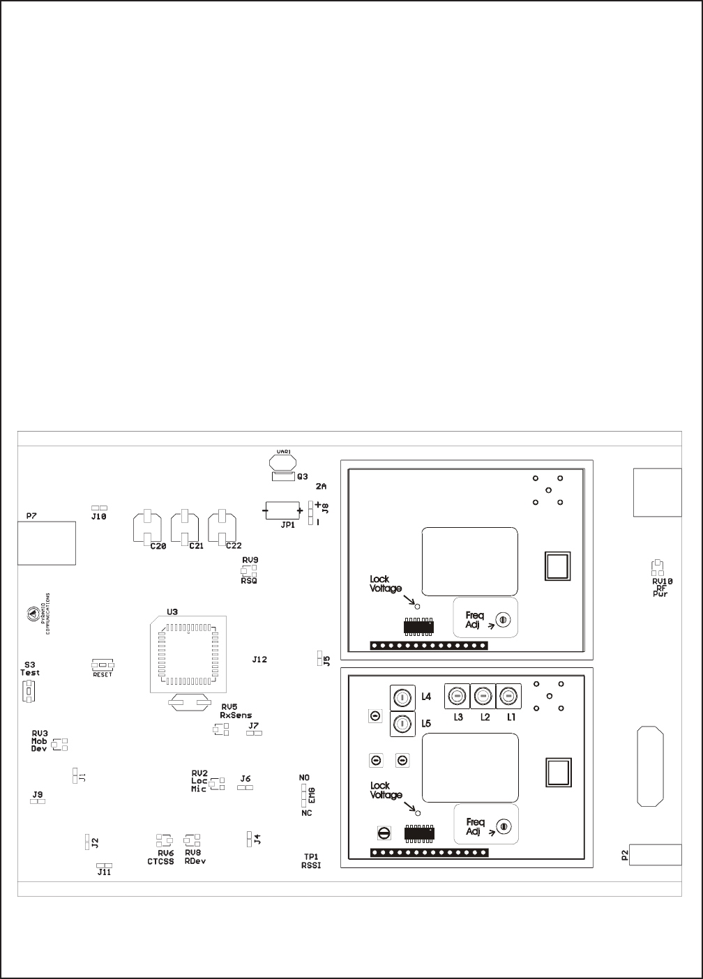
Alignment VHF
Before aligning the SVR-250, ensure that the mobile radio is aligned per the manufacturer’s service
procedure; Ensure that the SVR-250 is properly programmed and the jumpers are set per the previous section.
In order to properly align the SVR-250, you will need two service monitors and the mobile radio that the repeater
will be installed with. Refer to figure 1 for alignment points.
Dis-assemble the repeater by removing the two cap screws on the front panel; disconnect the front panel from
the main chassis by removing the 2 connectors. Remove the two cap screws from the rear panel and slide the main
circuit board out of the housing with the rear panel attached. Re-connect the front panel to the main PCB. Connect
one service monitor to the SVR-250 TNC jack and the other to the mobile antenna jack. Connect the cable from
the mobile radio to the SVR-250 (See figure 4 on page 16). Turn on the mobile and activate the SVR-250.
Adjust the repeater squelch control (RV9) so that the repeater COR led is off. Adjust the mobile so that the audio
is squelched.
SVR-250 VHF Transmitter
1. Transmitter Output: Push S3 and adjust RV10 for maximum. Confirm the SVR-250 RF Power out is at least
2W. Adjust RV10 for 250 mW.
2. Transmitter frequency: Adjust the TCXO on the Tx RF board for the transmit frequency.
3. Maximum deviation/lock tone deviation: If the SVR-250 is programmed for sub-audible encode, adjust RV6
(CTCSS) for minimum. Adjust RV8 (repeater deviation) for 80% deviation; adjust RV6 for total 95%
deviation (sub-audible and lock tone). If programmed for carrier squelch transmit adjust RV8 for 95%
deviation. Release S3.
4. Mobile COR: Measure the voltage at TP2 on the SVR-250 main PCB and record. Ensure the mobile COR
LED on the front panel is off. Set the mobile service monitor for the mobile receive frequency, 1mV RF output
and CTCSS modulation of 15% deviation. Measure the voltage again at TP2 and record. Ensure the mobile
COR LED on the front panel is on. The 2 voltages at TP2 must be at greater than 2.1VDC and less than 1.1
VDC.
5. RX audio sensitivity/CTCSS deviation: Set the service monitor connected to the mobile for the mobile receive
frequency and 1mV RF output. Modulate the signal generator with a 1kHz tone at 60% deviation and CTCSS
tone at 15% deviation. Ensure that the SVR-250 mobile COR and repeater PTT LED’s are on. If the
SVR-250 is programmed for sub-audible encode adjust RV5 on the SVR-250 main board for 75% deviation,
adjust for 60% deviation if carrier squelch transmit, as read on the service monitor connected to the SVR-250.
Turn the RF output from the mobile service monitor off and ensure that the SVR-250 mobile COR and repeater
PTT LEDs are off.
6. Local mic repeat: If the SVR-250 is programmed for local mic repeat, key the mobile local mic and inject an
audio signal into the local mic to produce 60% deviation on the service monitor connected to the mobile.
Confirm that the SVR-250 repeater PTT LED is on; adjust RV2 for 60% deviation as read on the service
monitor connected to the SVR-250. Unkey the mobile radio.
7. RF power out: Press S3 and adjust RV10 for the operating power output. Release S3.
Page 11
SVR-250 Service Manual
Figure 1
VHF Receiver
1. Receiver front end: Connect a DC voltmeter to TP1 on the SVR-250 main board. Set the service monitor
connected to the SVR-250 to the generate mode, receive frequency with a 1kHz tone and 60% deviation.
Adjust the RF output of the monitor for a 1VDC reading at TP1. Adjust L1-L5 on the RF board for a maximum
reading at TP1.
2. Repeater squelch: Adjust the service monitor RF output for .5μV. Adjust RV9 on the SVR-250 main board
so the repeater COR LED is just on. Decrease the service monitor RF output to .3μV and ensure that the
repeater COR LED is off.
3. Transmit audio output: Adjust the service monitor RF output for 1mV. Turn the CTCSS modulation on and
set for 15% deviation. Confirm that the repeater COR, CTCSS and mobile PTT LED’s are on. Adjust RV3
on the SVR-250 main board for 60% deviation as read on the service monitor connected to the mobile radio.
Turn off the CTCSS modulation of the service monitor connected to the SVR-250. Confirm that the repeater
CTCSS and mobile PTT LED’s are off.
4. Lock Tone Decode: Change the 1kHz tone modulation to the lock tone frequency. Confirm that the PRI LED
goes off after approximately .5 seconds.

Page 12
SVR-250 Service Manual
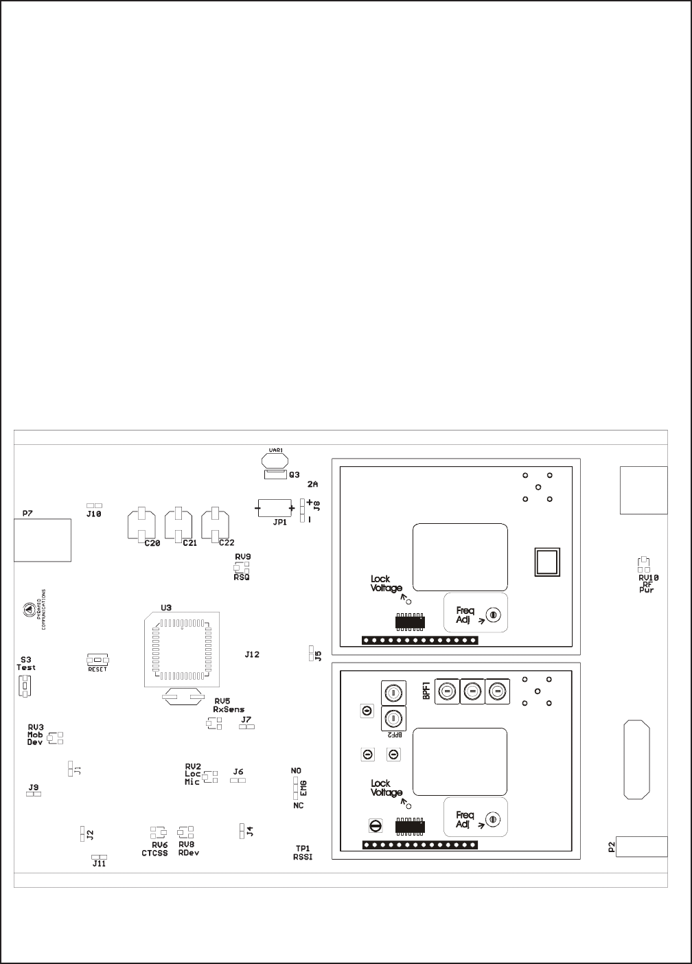
Alignment UHF
Before aligning the SVR-250, ensure that the mobile radio is aligned per the manufacturer’s service
procedure; Ensure that the SVR-250 is properly programmed and the jumpers are set per the previous section.
In order to properly align the SVR-250, you will need two service monitors and the mobile radio that the repeater
will be installed with. Refer to figure 2 for alignment points.
Dis-assemble the repeater by removing the two cap screws on the front panel; disconnect the front panel from
the main chassis by removing the 2 connectors. Remove the two cap screws from the rear panel and slide the main
circuit board out of the housing with the rear panel attached. Re-connect the front panel to the main PCB. Connect
one service monitor to the SVR-250 TNC jack and the other to the mobile antenna jack. Connect the cable from
the mobile radio to the SVR-250 (See figure 4 on page 16). Turn on the mobile and activate the SVR-250.
Adjust the repeater squelch control (RV9) so that the repeater COR led is off. Adjust the mobile so that the audio
is squelched.
SVR-250 UHF Transmitter
1. Transmitter Output: Push S3 and adjust RV10 for maximum. Confirm the SVR-250 RF Power out is at least
2W. Adjust RV10 for 250 mW.
2. Transmitter frequency: Adjust the TCXO on the Tx RF board for the transmit frequency.
3. Maximum deviation/lock tone deviation: If the SVR-250 is programmed for sub-audible encode, adjust RV6
(CTCSS) for minimum. Adjust RV8 (repeater deviation) for 80% deviation; adjust RV6 for total 95%
deviation (sub-audible and lock tone). If programmed for carrier squelch transmit adjust RV8 for 95%
deviation. Release S3.
4. Mobile COR: Measure the voltage at TP2 on the SVR-250 main PCB and record. Ensure the mobile COR
LED on the front panel is off. Set the mobile service monitor for the mobile receive frequency, 1mV RF output
and CTCSS modulation of 15% deviation. Measure the voltage again at TP2 and record. Ensure the mobile
COR LED on the front panel is on. The 2 voltages at TP2 must be at greater than 2.1VDC and less than 1.1
VDC.
5. RX audio sensitivity/CTCSS deviation: Set the service monitor connected to the mobile for the mobile receive
frequency and 1mV RF output. Modulate the signal generator with a 1kHz tone at 60% deviation and CTCSS
tone at 15% deviation. Ensure that the SVR-250 mobile COR and repeater PTT LED’s are on. If the
SVR-250 is programmed for sub-audible encode adjust RV5 on the SVR-250 main board for 75% deviation,
adjust for 60% deviation if carrier squelch transmit, as read on the service monitor connected to the SVR-250.
Turn the RF output from the mobile service monitor off and ensure that the SVR-250 mobile COR and repeater
PTT LEDs are off.
6. Local mic repeat: If the SVR-250 is programmed for local mic repeat, key the mobile local mic and inject an
audio signal into the local mic to produce 60% deviation on the service monitor connected to the mobile.
Confirm that the SVR-250 repeater PTT LED is on; adjust RV2 for 60% deviation as read on the service
monitor connected to the SVR-250. Unkey the mobile radio.
7. RF power out: Press S3 and adjust RV10 for the operating power output. Release S3.
Page 13
SVR-250 Service Manual
Figure 2
UHF Receiver
1. Receiver front end: Connect a DC voltmeter to TP1 on the SVR-250 main board. Set the service monitor
connected to the SVR-250 to the generate mode, receive frequency with a 1kHz tone and 60% deviation.
Adjust the RF output of the monitor for a 1VDC reading at TP1. Adjust BPF1 and BPF2 on the RF board for
a maximum reading at TP1.
2. Repeater squelch: Adjust the service monitor RF output for .5μV. Adjust RV9 on the SVR-250 main board
so the repeater COR LED is just on. Decrease the service monitor RF output to .3μV and ensure that the
repeater COR LED is off.
3. Transmit audio output: Adjust the service monitor RF output for 1mV. Turn the CTCSS modulation on and
set for 15% deviation. Confirm that the repeater COR, CTCSS and mobile PTT LED’s are on. Adjust RV3
on the SVR-250 main board for 60% deviation as read on the service monitor connected to the mobile radio.
Turn off the CTCSS modulation of the service monitor connected to the SVR-250. Confirm that the repeater
CTCSS and mobile PTT LED’s are off.
4. Lock Tone Decode: Change the 1kHz tone modulation to the lock tone frequency. Confirm that the PRI LED
goes off after approximately .5 seconds.

Page 14
SVR-250 Service Manual
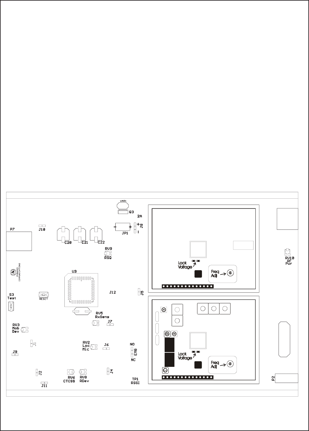
Alignment 700/800/900 MHz
Before aligning the SVR-250, ensure that the mobile radio is aligned per the manufacturer’s service
procedure; Ensure that the SVR-250 is properly programmed and the jumpers are set per the previous section.
In order to properly align the SVR-250, you will need two service monitors and the mobile radio that the repeater
will be installed with. Refer to figure 3 for alignment points.
Dis-assemble the repeater by removing the two cap screws on the front panel; disconnect the front panel from
the main chassis by removing the 2 connectors. Remove the two cap screws from the rear panel and slide the main
circuit board out of the housing with the rear panel attached. Re-connect the front panel to the main PCB. Connect
one service monitor to the SVR-250 TNC jack and the other to the mobile antenna jack. Connect the cable from
the mobile radio to the SVR-250 (See figure 4 on page 16). Turn on the mobile and activate the SVR-250.
Adjust the repeater squelch control (RV9) so that the repeater COR led is off. Adjust the mobile so that the audio
is squelched.
SVR-250 Transmitter
1. Transmitter Output: Push S3 and adjust RV10 for maximum. Confirm the SVR-250 RF Power out is at least
600mW. Adjust RV10 for 100 mW.
2. Transmitter frequency: Adjust the TCXO on the Tx RF board for the transmit frequency.
3. Maximum deviation/lock tone deviation: If the SVR-250 is programmed for sub-audible encode, adjust RV6
(CTCSS) for minimum. Adjust RV8 (repeater deviation) for 80% deviation; adjust RV6 for total 95%
deviation (sub-audible and lock tone). If programmed for carrier squelch transmit adjust RV8 for 95%
deviation. Release S3.
4. Mobile COR: Measure the voltage at TP2 on the SVR-250 main PCB and record. Ensure the mobile COR
LED on the front panel is off. Set the mobile service monitor for the mobile receive frequency, 1mV RF output
and CTCSS modulation of 15% deviation. Measure the voltage again at TP2 and record. Ensure the mobile
COR LED on the front panel is on. The 2 voltages at TP2 must be at greater than 2.1VDC and less than 1.1
VDC.
5. RX audio sensitivity/CTCSS deviation: Set the service monitor connected to the mobile for the mobile receive
frequency and 1mV RF output. Modulate the signal generator with a 1kHz tone at 60% deviation and CTCSS
tone at 15% deviation. Ensure that the SVR-250 mobile COR and repeater PTT LED’s are on. If the
SVR-250 is programmed for sub-audible encode adjust RV5 on the SVR-250 main board for 75% deviation,
adjust for 60% deviation if carrier squelch transmit, as read on the service monitor connected to the SVR-250.
Turn the RF output from the mobile service monitor off and ensure that the SVR-250 mobile COR and repeater
PTT LEDs are off.
6. Local mic repeat: If the SVR-250 is programmed for local mic repeat, key the mobile local mic and inject an
audio signal into the local mic to produce 60% deviation on the service monitor connected to the mobile.
Confirm that the SVR-250 repeater PTT LED is on; adjust RV2 for 60% deviation as read on the service
monitor connected to the SVR-250. Unkey the mobile radio.
7. RF power out: Press S3 and adjust RV10 for the operating power output. Release S3.
Page 15
SVR-250 Service Manual
Figure 3
700/800/900 MHz Receiver
1. Receiver front end: Connect a DC voltmeter to TP1 on the SVR-250 main board. Set the service monitor
connected to the SVR-250 to the generate mode, receive frequency at .5μV RF output with a 1kHz tone and
60% deviation. Confirm a reading of 1VDC ±.2VDC at TP1.
2. Repeater squelch: Adjust the service monitor RF output for .5μV. Adjust RV9 on the SVR-250 main board
so the repeater COR LED is just on. Decrease the service monitor RF output to .25μV and ensure that the
repeater COR LED is off.
3. Transmit audio output: Adjust the service monitor RF output for 1mV. Turn the CTCSS modulation on and
set for 15% deviation. Confirm that the repeater COR, CTCSS and mobile PTT LED’s are on. Adjust RV3
on the SVR-200 main board for 60% deviation as read on the service monitor connected to the mobile radio.
Turn off the CTCSS modulation of the service monitor connected to the SVR-250. Confirm that the repeater
CTCSS and mobile PTT LED’s are off.
4. Lock Tone Decode: Change the 1kHz tone modulation to the lock tone frequency. Confirm that the PRI LED
goes off after approximately .5 seconds.
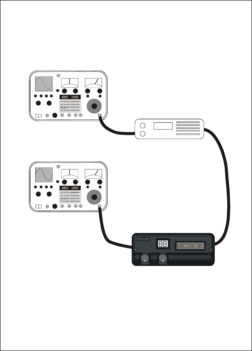
Page 16
SVR-250 Service Manual
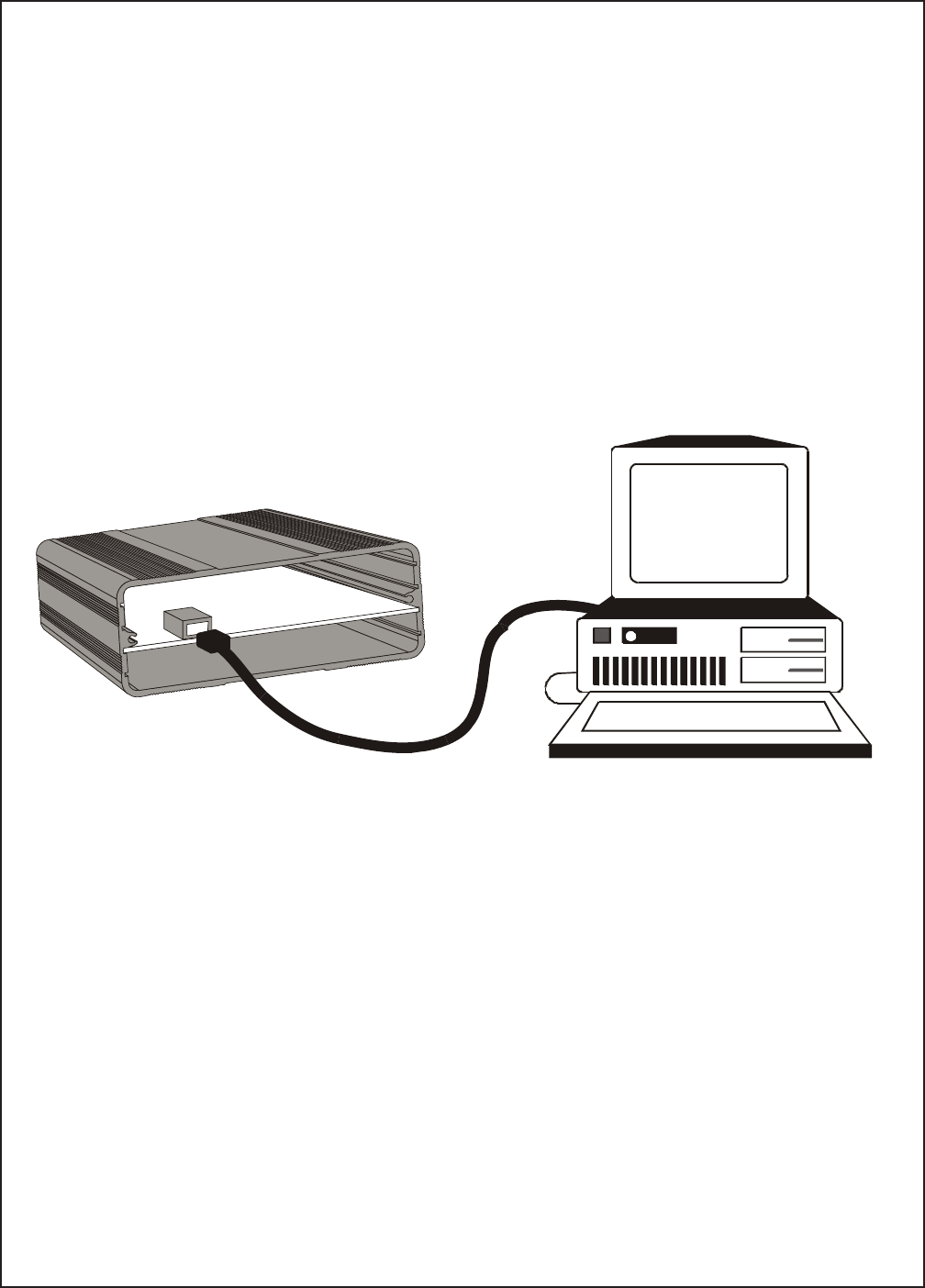
Figure 4
Mobile Radio
Communications
Monitor A
Communications
Monitor B
SVR-250
Interface
Cable
Page 17
SVR-250 Service Manual
Menu selections
File
Open: Allows you to load a previously saved file from disk. Enter the file name or select from the Windows Dialog
box. Only files with the .V25 extension can be loaded.
Save: Allows you to save the current configuration to disk. Enter the file name to save as or select a previous file
from the Windows Dialog box to overwrite. The .V25 extension is automatically added to the file name. The
program will prompt you before overwriting an existing file.
Print: Sends the current configuration to the selected printer. Make sure the printer is on line and paper is loaded
before executing this command.
Exit: You will be asked to confirm before exiting the program. The software will also prompt you if the
configuration has changed since program start up and data has not been saved to disk.
Programming
Using the Software
The SVR250CPS personalization software is used to program the SVR-250 for all of the operating parameters
and options. The software is compatible with Windows 2000 and later operating systems The software is menu
driven and on-line help is available at any time by clicking the left mouse button on the HELP icon on the right
side of the tool bar.
Important Note:
Before attempting to program the SVR-250 start the software and ensure the FY-4 programming cable is
plugged into the correct serial port. The com port may be selected under the “Transfer” menu. Plug the FY-4
programming cable into P7 on the front of the SVR-250; the channel indicator should show "PC".
Page 18
SVR-250 Service Manual
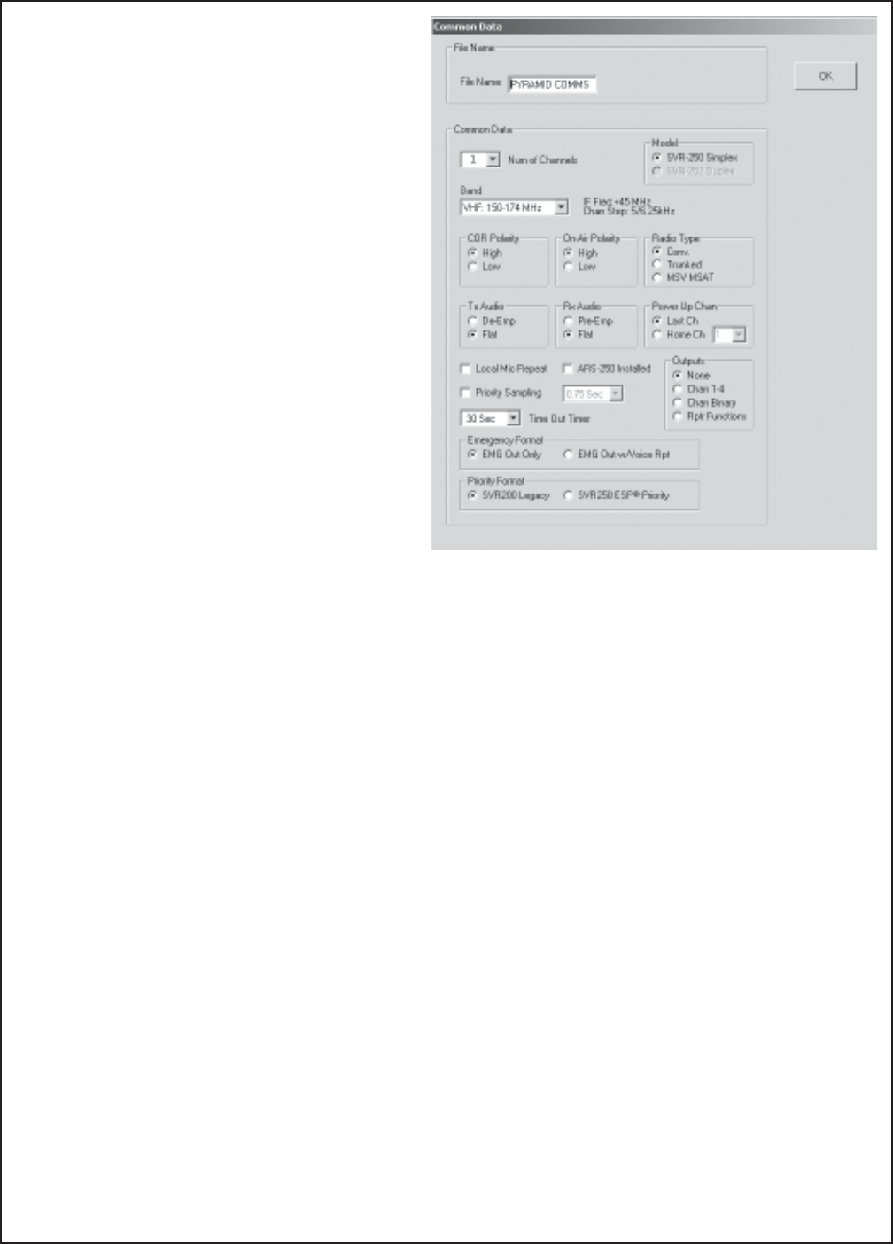
Common Data
File Name: 15 character name for this profile stored
in E²PROM.
Number of Channels: Select 1-20 channels
Model: Select either simplex or Duplex. Duplex
operation requires hardware and firmware changes
and is not field upgradable.
Band: Select the frequency band to match your
SVR-250. Changing bands resets all data to default
values (confirmation req.)
COR Polarity: Determines if the COR signal from
the mobile is active high or low.
On-Air Polarity: Determines if the Tx indication
from the mobile is active high or low.
Mobile Type: Select either Conventional, Trunking
or MSV Satellite. If Trunking or MSV is selected,
the SVR-250 will go through the voice channel
acquisition procedure during portable-to-base repeat
mode.
Tx Audio: If the mobile Tx audio from the SVR-250 to the mobile is connected after pre-emphasis, select Flat
response. If connected before pre-emphasis or to the mic input, select De-Emp.
Rx Audio: If the Rx audio from the mobile to the SVR-250 is connected to the discriminator or before
de-emphasis, select Flat response. If connected after de-emphasis, select Pre-Emp.
Power Up Channel: Select either Last Channel or Home Channel.
Local Mic Repeat: Enables or disables the local mic repeat function; if enabled, ensure the on-air polarity is set
correctly and the Grey wire or J5 is configured correctly (see pages 8 & 9).
ARS-250: Check this box only if the ARS-250 Auxiliary receiver is installed. The ARS-250 is used by non-priority
units to sense mobile transmitters in half-duplex systems.
Outputs: The SVR-250 has 4 general purpose outputs that can be programmed to follow the channel selector and
output chan 1-4 (Single Output) or chan 1-15 (Binary Output), or Repeater Functions for Priority, Transmit and
PL Decode. The outputs are open collector and active low. The outputs can also be disabled in software (None).
Priority Sampling: If the SVR-250 is used in a multi-vehicle environment, priority sampling must be enabled for
proper operation.
Sampling Rate: If Priority sampling is enabled, this selects the sampling interval. Range is 0.25 seconds to 2.5
seconds in .25 sec increments. The higher this setting, the longer the handheld operator must wait before speaking
after pressing PTT during base-to-portable sampling.
Time Out Timer: This is the maximum duration of a single base to portable transmission that will be allowed.
Emergency Format: Emg Out Only will assert pin 10 of the main connector for as long as secondary tone is
decoded. Emg Out with voice will assert pin 10 but also repeat portable-to-base mode.
Priority Format: The SVR-250 has an enhanced signalling format to determine if the priority vehicle has left the
scene during idle time. Select SVR-200 legacy to turn off this feature. Both formats are fully SVR-200 compatible.
Page 19
SVR-250 Service Manual
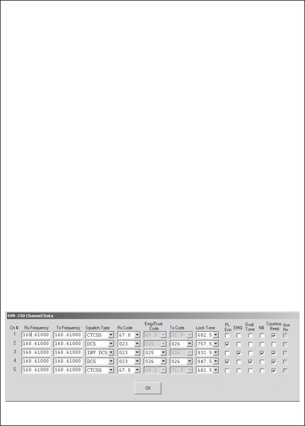
Channel Data
Note: The number of channels available is determined by the setting in Common Data.
Tx and Rx Frequency: Enter the Transmit and Receive frequencies for each channel. The frequency must be
in the range for the band selected under Common Data and will be rounded to the nearest channel step.
Squelch Type: Select either CTCSS, DCS or Inverted DCS. These can be selected on a per channel basis, but
cannot be mixed with a channel.
Rx Code: The primary tone/code, when received will put the SVR-250 into portable-to-base repeat mode.
Emg/Dual Code: The secondary tone/code, when received will initiate an Emergency sequence or confirm
reception of other SVR-250s in an application with co-channel interference. Emergency and Dual tone are
mutually exclusive. See page 6 for a complete description of these modes.
Tx Code: In normal operation, the SVR-250 does not transmit sub-audible signalling. If enabled, the Tx code
should not be the same as the primary Rx Code. If Dual Tone mode is enabled, the Tx Code must match the
secondary code.
Lock Tone: This is the tone burst first transmitted when the SVR-250 is enabled and sent every 10 seconds if
ESPTM priority mode is selected. The tone must be the same in all vehicular repeaters in the system.
PL Encode: If selected, sub-audible transmit is enabled for that channel.
EMG: If selected, the Emergency function is enabled for that channel. Emergency and Dual Tone are mutually
exclusive.
Dual Tone: If selected, the Dual Tone Receive function is enabled for that channel. Emergency and Dual Tone
are mutually exclusive.
NB: If selected, the channel BW is 12.5/15 kHz. If not selected the channel BW is 25/30kHz. Low Band is 20kHz
only. 700 and 900 MHz are 12.5kHz only.
Courtesy Beep: If selected, a short beep will be sent to the handheld user at the end of each portable-to-base
transmission to confirm they are still within range.
Aux Rx: If enabled under common data and selected for a channel, the non-priority SVR-250s will look to the
auxiliary receiver for mobile COR rather than to their own mobile radios.
)

Page 20
SVR-250 Service Manual
Transfer
Send: Downloads the current configuration to the SVR-250. The program will prompt you to make the FY-4
connection before downloading. Download takes approx 2 seconds.
Receive: Uploads the current configuration from the SVR-250. The program will prompt you to make the
FY-4 connection before uploading. Download takes approx 1 second.
Com Port: Selects the serial port to use for uploading and downloading between the PC and the SVR-250. Comm
ports 1-8 are supported.
Help
On-line context sensitive help is available for all entry fields by selecting the field on a form and clicking on the
Help Icon on the tool bar.
Additional help menu items:
About: Gives you version information about the software and contact information for Pyramid Communications.
Remote Tech Support: Remote Tech Support is a utility that allows the Customer Service Technicians at Pyramid
Communications to remotely access your computer via the internet in order to troubleshoot any problems you
might be having with the software or to assist you in operation of the program. Please call Pyramid
Communications during normal business hours prior to selecting remote support. The Technician will give you
a password to enter and the remote connection screen will appear:
Once the internet connection is made, the Technician will be able to see your computer screen at their location
and assist you with the program. The remote connection is only active when this item is selected and can only
be enabled by the local PC user.
Page 21
SVR-250 Service Manual
ARS-250 Programming
The ARS-250 is a 16 channel auxiliary scanning receiver that provides mobile COR to the SVR-250 logic in
half duplex systems that do not repeat car to car. The ARS-250 mounts inside the SVR-250 extrusion and is
programmed to the mobile transmit frequency. When the SVR-250 is at non-priority status and a portable-to-base
repeat condition exists, the ARS-250 COR output is sampled rather than the mobile COR. The Aux Rx option
can be enabled or disabled in the SVR-250 on a per channel basis.
The ARS-250 should be programmed with all mobile frequencies that will need to be monitored, including
CTCSS or DCS if needed. Programming the ARS-250 is done through the same programming socket (P7) as the
SVR-250, using the ARS-250CPS software:
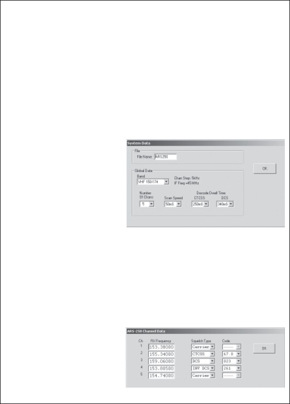
Common Data
File Name: 15 character name for this profile stored in E²PROM.
Band: Select the frequency band to match your ARS-250. Changing bands resets all data to default values
(confirmation required.)
Number of Chans: Select the number of
channels to scan. Range 1-16.
Scan Speed: Scan speed is determined by the
time spent on each channel looking for carrier.
Default is 50mS (20 channels per second).
Decode Dwell Time: The amount of time the
receiver will pause to look for CTCSS or DCS
after Carrier is detected. If Dwell time is too
short, the receiver may not decode properly.
Channel Data
Note: The number of channels available is determined by the setting in Common Data.
Receive Frequency: Enter the Receive frequency for each channel. The frequency must be in the range for the
band selected under Common Data and will be rounded to the nearest channel step.
Squelch Type: Select Carrier Squelch, CTCSS, DCS or Inverted DCS.
Code: Select the CTCSS tone or DCS/Inv DCS code for each channel.
)
Page 22
SVR-250 Service Manual
Flash Programming
The SVR-250 uses an Atmel 89C51RB2 microprocessor which contains the operating system. The chip can be
reprogrammed in-circuit using Atmel's FLIP software and a PC running Windows 2000 or XP. The FLIP software
can be downloaded from Pyramid's web site:
www.pyramidcomm.com/support
Warning- Do not attempt to re-flash the SVR-250 μP unless you are familiar with operation
of the SVR-250 and reasonably competent using Windows software. If the μP is not programmed
correctly, it can render the SVR-250 inoperable.
Install the software onto your PC; the download will include several config (.cfg) and hex data (.hex) files.
Ensure these are copied into the \Program Files\Atmel directory on your computer. Perform the flash
programming in the EXACT steps as outlined below:
Prior to starting the FLIP software, disassemble the SVR-250 by removing the 2 cap screws on the front panel.
Disconnect the front panel from the main PCB by unplugging the 2 cables. Remove the 2 cap screws from the
rear panel and carefully slide the entire assembly out of the extrusion. Reconnect the front panel to the main PCB.
Connect the radio cable to the SVR-250 and apply power. Connect the FY-4 DB9 connector to your computer
and the modular connector to P7 at the front of the SVR-250 main PCB; the channel indicator should show "PC".
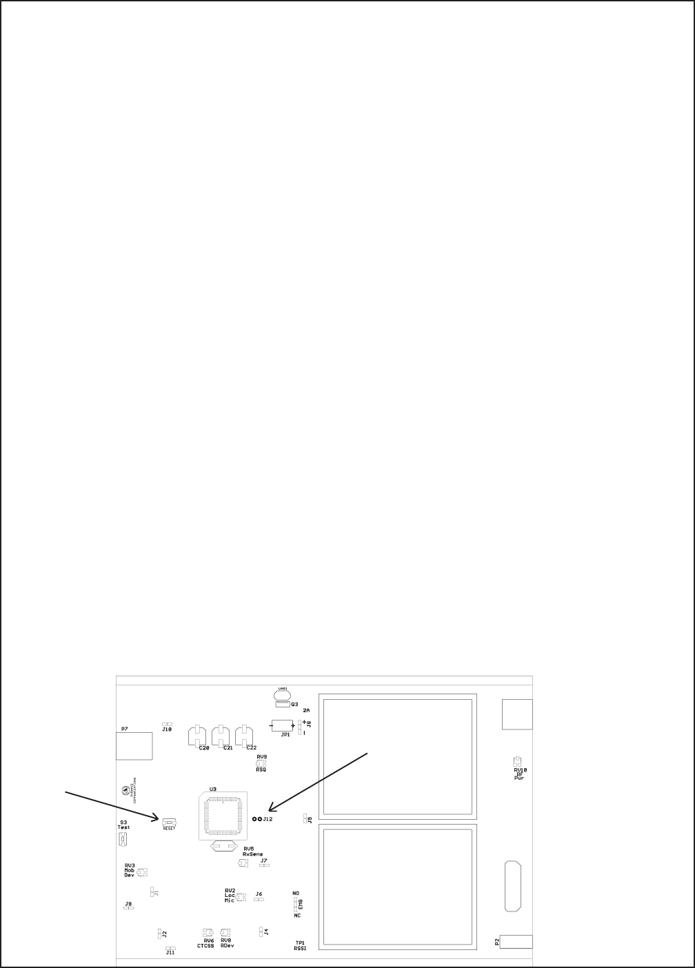
Start the FLIP software. Install a shorting jumper onto J12.
Flash Program U3:
1. Press the Reset switch S2. In the FLIP software, press F4 (load config) and locate the Atmel directory on your
computer; select and load the SVR250.cfg file. The FLIP software will automatically establish communications
with the IC in the SVR-250. If it does not, wait until it times out, click OK to close the error message, check
the com port, cable etc., and start at the beginning of step 1. When FLIP is successful, it will populate the device
data fields on the right side of the PC screen. Do not change any of these settings!
2. On the left side of the screen, confirm the Erase, Blank Check, Program and Verify boxes are checked. In the
center of the screen, confirm the SVR-250.HEX file is loaded. Click the Run button to flash U3 with the hex
file. Each of the checked boxes will turn green in series as things progress. If any of them fail, verify all of
the connections as above and start over at step 1.
J12
Reset
,

Page 23
SVR-250 Service Manual
Notes:
This page intentially left blank

Page 24
SVR-250 Service Manual
Theory of Operation
Receiver:
The receiver is a double-conversion superheterodyne type, designed for narrow band FM reception. The first
local oscillator is derived from the frequency synthesizer. The second LO is crystal controlled.
RF Stage: The incoming RF signal from the antenna jack is directed to the first RF bandpass filter to improve
selectivity and then to the input of the RF amplifier. The output of the RF amplifier is then presented to a second
bandpass filter.
First LO/Mixer: The first LO signal is developed by the synthesizer and is mixed with the incoming signal to
produce the first IF frequency (45 MHz). The IF frequency is filtered by FL1A and FL1B and amplified by the
IF amplifier before being presented to the second LO/Mixer IC.
Second LO/Mixer: The first IF signal is presented to the second IF IC (MC3371) which performs the functions
of second LO, second IF amp and mixer, FM discriminator and squelch. The second LO crystal (44.545 MHz)
is mixed with the 45 MHz first IF signal to produce the second IF frequency of 455 kHz. Two 6 pole ceramic filters
provides selectivity for the 455 kHz signal and are switchable between narrow band and wide band.
Detector/Squelch: The MC3371 demodulates the 455 kHz signal via quadrature coil to produce the audio and
noise components. The output of the MC3371 is the recovered audio and the RSSI voltage (receiver signal strength
indicator) which is compared by the controller board with a threshold voltage level for squelch setting.
VHF Transmitter
The output of VCO buffer U8 is input to the predriver transistor U7. The output of U7 drives the RF driver
Q8. The collector of Q8 is fed by the transmit 9V line from Q10. The final amp Q13 is a class C power amplifier
and drives the output lowpass and harmonic filter, C47-C50 and L20-L22. D3 is the transmit output switch and
L19 is a ¼ wave transmission line to isolate the receiver switching diode D2. RF output power is controlled by
changing the bias on the gate of Q13 via the TX 9V line (pin 3) from the controller PCB.
UHF Transmitter
The output of VCO buffer U6 is input to the predriver transistor U5. The output of U5 drives the RF driver
transistor Q4. The collector of Q4 is fed by the transmit 9V line from Q5. The final amp Q3 is a class C power
amplifier and drives the output lowpass and harmonic filter, C39-C42 and L26-L28. D3 is the transmit output
switch and L14 is a ¼ wave transmission line to isolate the receiver switching diode D2. RF output power is
controlled by changing the bias on the gate of Q3 via the TX 9V line (pin 3) from the controller PCB.
700/800/900 MHz Transmitter
The output of the transmit VCO is buffered by U5 input to the driver transistor U1. The output of U1 drives
the RF hybrid output amp U4 through lowpass filter FL3. The final amp U4 is a class C power amplifier and drives
the output lowpass and harmonic filter FL4. U7 is the Tx/Rx antenna switch. RF output power is controlled by
changing the voltage on pin 1 of U4 via the TX 9V line (pin 3) from the controller PCB.

Page 25
SVR-250 Service Manual
Control Board
Power Supply: DC power comes from the mobile radio via P1 pins 1 and 5. Fuse F1 and MOV VAR1 provide
over current and voltage spike protection. Q3 is the remote enable/disable pass switch, controlled by Q1 and Q2
via P1 pin 3. Q3 output is switched 12VDC and is presented to audio amp U6, and voltage regulators U7 and U8.
Bias voltage for the op-amp circuits is provided by U10 pin 10 and buffer amp U9D.
Transmit audio path: Receiver audio from the mobile is input on pin 6 of P1 and routed to op amp U16B; RV5
sets the sensitivity. The output of U16B goes to the mic amp portion of U10; PC programming of the SVR-250
provides flat response or +6db/octave pre-emphasis. U10 provides all of the audio processing, limiting and
filtering of the transmit audio. Transmit voice audio is output on pin 19 of U10, sub-audible signals on pin 20.
U17B and U17C select the voice and subaudio paths from U10 (simplex) or U11 (duplex operation). The selected
audio is summed by U9A & U9B and passes through the final lowpass filter U9C to remove any clock noise
generated by U10 before being presented to the RF module on P4 pin 6.
Receive audio path: Receiver audio from the receiver module is input on P5 pin 13 and routed to U10 pin 11. U10
provides all of the receive audio processing and filtering, in-band and subaudible tone decoding. The receive audio
is output on U10 pin 22, where it is sent to the local receiver audio amp and mobile transmit audio output amp U1A.
J1 selects either high sensitivity (open) or low sensitivity (shorted) and J2 selects the output impedance (600/2.2K
Ohms). J11 inserts (open) or removes (shorted) a 100KOhm series resistor for radios with low level mic audio
and alternator whine problems.
RF Tx and Rx paths: For simplex operation, U15 switches the single TNC antenna connector P10 between the
Tx and Rx module. In duplex operation, the coax between MCX connectors P8 and P9 is removed and the receive
module is connected directly to TNC connector P11 via J14. If the Auxiliary receiver is installed, it shares the
Rx module antenna connection via the RF attenuator comprised of R201-203. D4 forms the Tx RF detector and
U12 is the Automatic Power Control for the transmitter. RV10 sets the reference voltage for the RF power out
and control TX9V pass transistor Q4.
LED Display: The front panel display contains 2 seven segment displays and 8 LED status indicators. The 3
displays are driven by 3 shift registers in series under control of the main μP and updated every 10mS via P3.
Logic and control: U3 is an Atmel 89C51RB2 microprocessor with flash E²PROM memory. The microprocessor
provides all of the logic and control functions for the repeater including mobile/repeater PTT output, local mobile
PTT sense, mobile transmitter activity sense, audio switching, in-band & CTCSS detect, channel number and
repeater status indications via front panel led arrays.