Q Logic Qla12160 Users Manual
QLA12160 to the manual c767d68c-2c30-46fb-91ca-29955ec48c32
2015-02-05
: Q-Logic Q-Logic-Qla12160-Users-Manual-492450 q-logic-qla12160-users-manual-492450 q-logic pdf
Open the PDF directly: View PDF ![]() .
.
Page Count: 30
- Table of Contents
- Section 1 Introduction
- Section 2 Hardware Installation
- Section 3 Troubleshooting
- Appendix A Fast!UTIL
- Appendix B SCSI Termination
- Appendix C Specifications

Hardware Installation Guide for the
QLA12160 Board
64-Bit PCI Dual SCSI Host Adapter Board
for the PCI Bus
DC8151101-00 C
September 14, 2001

QLogic Corporation
Page ii DC8151101-00 C
Information furnished in this manual is believed to be accurate and reliable.
However, QLogic Corporation assumes no responsibility for its use, nor for any
infringements of patents or other rights of third parties which may result from its use.
QLogic Corporation reserves the right to change product specifications at any time
without notice. Applications described in this document for any of these products
are for illustrative purposes only. QLogic Corporation makes no representation nor
warranty that such applications are suitable for the specified use without further
testing or modification. QLogic Corporation assumes no responsibility for any errors
that may appear in this document.
No part of this document may be copied nor reproduced by any means, nor
translated nor transmitted to any magnetic medium without the express written
consent of QLogic Corporation.
QLogic is a trademark of QLogic Corporation.
Seagate is a trademark of Seagate Technology, Inc.
Microsoft is a trademark of Microsoft Corporation.
All other brand and product names are trademarks or registered trademarks of
their respective owners.
Document Revision History
Rev. A initial release, 6/22/99
Rev. B, update, 5/24/00 (QL12160L board added)
Rev. C, update, 9/14/01 (QLA12160L board deleted)
Boards Affected
QLA12160 (DC8110402)
Changes Sections Affected
Deleted QLA12160L All
Added 4 GB Addressing and Fast Command Posting
to host adapter settings A.2.1
Moved SCSI ID, SCSI bus reset, SCSI bus reset
delay, and SCSI termination from host adapter
settings to SCSI bus settings
A.2.1, A.2.3
Deleted Host Adapter and Concurrent Command/
Data from host adapter settings A.2.1
© 1999–2001 QLogic Corporation
First Printed: June 1999
All Rights Reserved Worldwide.
Printed in U.S.A.
QLogic Corporation, 26600 Laguna Hills Drive, Aliso Viejo, CA 92656
(800) 867-7274 or (949) 389-6000

DC8151101-00 C Page iii
Table of Contents
Section 1 Introduction
1.1 Product Description . . . . . . . . . . . . . . . . . . . . . . . . . . . . . . . . 1-1
1.2 Features . . . . . . . . . . . . . . . . . . . . . . . . . . . . . . . . . . . . . . . . 1-2
1.2.1 Mixed Peripheral Support . . . . . . . . . . . . . . . . . . . . . . . . 1-3
Section 2 Hardware Installation
2.1 Preinstallation Procedures. . . . . . . . . . . . . . . . . . . . . . . . . . . 2-1
2.2 What You Need for Installation . . . . . . . . . . . . . . . . . . . . . . . 2-1
2.3 Setting the SCSI Termination . . . . . . . . . . . . . . . . . . . . . . . . 2-2
2.4 SCSI Termination Power. . . . . . . . . . . . . . . . . . . . . . . . . . . . 2-2
2.5 Installing the Device Activity Light . . . . . . . . . . . . . . . . . . . . . 2-2
2.6 Installation in the Computer. . . . . . . . . . . . . . . . . . . . . . . . . . 2-3
2.7 Installation Help. . . . . . . . . . . . . . . . . . . . . . . . . . . . . . . . . . . 2-5
Section 3 Troubleshooting
3.1 Problems After Installation. . . . . . . . . . . . . . . . . . . . . . . . . . . 3-1
3.2 Hardware Problem Checklist. . . . . . . . . . . . . . . . . . . . . . . . . 3-1
3.3 System Configuration Problem Checklist . . . . . . . . . . . . . . . 3-1
3.4 SCSI Problem Checklist . . . . . . . . . . . . . . . . . . . . . . . . . . . . 3-2
Appendix A Fast!UTIL
A.1 Introduction . . . . . . . . . . . . . . . . . . . . . . . . . . . . . . . . . . . . . . A-1
A.2 Configuration Settings . . . . . . . . . . . . . . . . . . . . . . . . . . . . . A-1
A.2.1 Host Adapter Settings . . . . . . . . . . . . . . . . . . . . . . . . . . . A-2
A.2.2 SCSI Device Settings . . . . . . . . . . . . . . . . . . . . . . . . . . . A-3
A.2.3 SCSI Bus Settings . . . . . . . . . . . . . . . . . . . . . . . . . . . . . . A-5
A.2.4 Autoconfigure SCSI Devices . . . . . . . . . . . . . . . . . . . . . . A-7
A.2.5 Selectable Boot Settings . . . . . . . . . . . . . . . . . . . . . . . . . A-7
A.2.6 Restore Default Settings . . . . . . . . . . . . . . . . . . . . . . . . . A-8
A.2.7 Raw NVRAM Data . . . . . . . . . . . . . . . . . . . . . . . . . . . . . . A-8
A.3 Scan SCSI Bus . . . . . . . . . . . . . . . . . . . . . . . . . . . . . . . . . . . A-8
A.4 SCSI Disk Utility . . . . . . . . . . . . . . . . . . . . . . . . . . . . . . . . . . A-8
A.5 Using SCSI-1 Devices . . . . . . . . . . . . . . . . . . . . . . . . . . . . . A-8

Table of Contents QLA12160 Hardware Installation Guide
Page iv DC8151101-00 C
Appendix B SCSI Termination
B.1 Setting the SCSI Termination . . . . . . . . . . . . . . . . . . . . . . . B-1
B.2 Termination (Jumpers) for the QLA12160 . . . . . . . . . . . . . . B-1
Appendix C Specifications
FIGURES
Figure Page
2-1 QLA12160 Board Layout. . . . . . . . . . . . . . . . . . . . . . . . . . . . . . . 2-2
B-1 QLA12160 Jumper Termination . . . . . . . . . . . . . . . . . . . . . . . . . B-2
TABLES
Table Page
1-1 SCSI Data Transfer Rates . . . . . . . . . . . . . . . . . . . . . . . . . . . . . 1-1
3-1 Maximum Cable Length . . . . . . . . . . . . . . . . . . . . . . . . . . . . . . . 3-2
A-1 Host Adapter Settings . . . . . . . . . . . . . . . . . . . . . . . . . . . . . . . . . A-2
A-2 SCSI Device Settings . . . . . . . . . . . . . . . . . . . . . . . . . . . . . . . . . A-3
A-3 SCSI Bus Settings. . . . . . . . . . . . . . . . . . . . . . . . . . . . . . . . . . . . A-5
A-4 QLA12160 Ports . . . . . . . . . . . . . . . . . . . . . . . . . . . . . . . . . . . . . A-6
C-1 QLA12160 Board Operating Environment . . . . . . . . . . . . . . . . . C-1
C-2 QLA12160 Board Specifications . . . . . . . . . . . . . . . . . . . . . . . . . C-1

DC8151101-00 C 1-1
Section 1
Introduction
NOTE: This installation guide applies to the following QLogic host adapter boards,
collectively referred to as the QLA12160 board unless otherwise noted:
■QLA12160/33 (DC8110402-06)
■QLA12160/66 (DC8110402-07)
The QLA12160 board (wide, low voltage differential [LVD]), dual port,
Ultra3, 64-bit PCI) contains the ISP12160A/33 or ISP12160A/66 chip.
1.1
Product Description
The QLA12160 board is an intelligent, high-performance, DMA bus master SCSI
host adapter designed for high-end systems. The intelligence and performance are
derived from the ISP chip, making the QLA12160 board a high performance host
adapter. The ISP chip combines a powerful RISC processor, two SCSI executive
processors (SXPs), and a peripheral component interconnect (PCI) local bus
interface in a single-chip solution. The QLA12160 board supports bootable devices
(hard disk drives and CD-ROM drives) and can be used with tape drives and other
SCSI devices. Installation of the QLA12160 board is quick and easy.
The QLA12160 board is for use only with UL listed computers that have detailed
instructions for user installation of accessory cards.
The QLA12160 board is designed to operate with multiple data transfer speeds
under SCSI specifications (see table 1-1).
NOTE: Only single-ended and LVD devices (Ultra2 and Ultra3) can be connected
to the QLA12160 board.
Table 1-1. SCSI Data Transfer Rates
SCSI Mode Maximum Data Rate
Narrow (8-bit) Maximum Data Rate
Wide (16-bit)
SCSI (or parallel SCSI) 5 MBps (asynchronous) —
Fast SCSI 10 MBps 20 MBps
Ultra SCSI 20 MBps 40 MBps
Ultra2, LVD SCSI 40 MBps 80 MBps
Ultra3, LVD SCSI 80 MBps 160 MBps

Features 1 – Introduction
1-2 DC8151101-00 C
The QLA12160 board supports Ultra, Ultra2, and Ultra3 transfer speeds. The board
can connect computers to other computers or to peripheral devices such as
CD-ROM drives, tape drives, and hard disk drives. SCSI allows connecting the
following numbers and types of devices to a single port by daisy chaining:
■15 fast, wide SCSI devices
■15 Ultra2 or Ultra3, LVD SCSI devices
■6 Ultra SCSI devices (QLA12160 board in single-ended mode)
A daisy chain is a series of connections where the first device is connected to the
host adapter board, the second device is connected to the first device, and so on.
A daisy chain can be created either by using a daisy chain cable (one cable with
multiple connectors) or by using multiple cables. Each SCSI device must have a
unique SCSI ID.
Because SCSI allows the computer to use a standard set of commands to
communicate with peripherals, adding a variety of peripherals to your computer
using one host adapter board is easy.
1.2
Features
■Compliance with Intel PCI version 2.2 specification
■Compliance with ANSI X3.131-1994 SCSI-2 standard
■Compliance with ANSI X3T10/1071D SCSI-3 Fast-20 standard (Ultra SCSI)
■Compliance with ANSI X3T10/1142D Fast-40 draft (Ultra2 SCSI)
■Compliance with ANSI T10 project 855D, Information Technology—SCSI-3
Parallel Interface (SPI)
■Compliance with ANSI T10 project 1142D, Information Technology—SCSI
Parallel Interface-2 (SPI-2)
■Compliance with ANSI T10 project 1302D, Information Technology—SCSI
Parallel Interface-3 (SPI-3)
■Compliance with U.S. and international safety and emissions standards
■Support for asynchronous and synchronous transfer modes
■Support for synchronous SCSI data transfer rates:
❑Ultra3, LVD SCSI (160 MBps)
❑Ultra2, LVD SCSI (80 MBps)
❑Ultra SCSI wide (40 MBps)
❑Ultra SCSI narrow (20 MBps)
❑Fast SCSI wide (20 MBps)
❑Fast SCSI narrow (10 MBps)
❑SCSI narrow (5 MBps)
■Support for single-ended mode

1 – Introduction Features
DC8151101-00 C 1-3
■Support for LVD mode
■Support for up to 30 LVD SCSI devices (15 per channel)
■Support for logical unit numbers (LUNs) 0–15
■Support for bus master DMA
■Fast!UTIL BIOS utility to customize the configuration parameters on the
QLA12160 board and attached drives
■Active termination
■Active negation
1.2.1
Mixed Peripheral Support
■Support for hard disk, removable disk, optical disk, scanner, tape drive,
CD-ROM, and other SCSI devices
■Simultaneous mixed-peripheral configurations support
■Bootable device support for disk and CD-ROM
■DOS advanced SCSI programming interface (ASPI) manager for disk, tape,
and other devices

Features 1 – Introduction
1-4 DC8151101-00 C

BC8151101-00 C 2-1
Section 2
Hardware Installation
2.1
Preinstallation Procedures
Before installing your QLA12160 board, take the time to read this instruction guide.
CAUTION!
■Your computer, the QLA12160 board, and each SCSI device must
be configured properly for optimum performance. Refer to the
appropriate documentation to configure your computer and SCSI
devices.
■Pay particular attention to the SCSI ID assignment. The QLA12160
board is set at the factory for SCSI ID 7. The QLA12160 board
and each SCSI device attached to the board must have
different SCSI IDs.
■The QLA12160 board contains parts that can be damaged by
electrostatic discharge (ESD). Before handling the QLA12160
board, use standard methods to discharge static electricity. Keep
the QLA12160 board in the antistatic bag until you are ready to
install it. Place the board on the bag when you examine or configure
it. Retain the bag for future use.
2.2
What You Need for Installation
Before you install the QLA12160 board in your computer, you need the following:
■A screwdriver (usually a Phillips #1)
■One or more of the following cables:
❑Internal narrow (68-pin to 50-pin)
❑Internal wide (68-pin to 68-pin)
❑External narrow (68-pin very high density cable [VHDC] to 50-pin)
❑External wide (68-pin VHDC)
Setting the SCSI Termination 2 – Hardware Installation
2-2 BC8151101-00 C
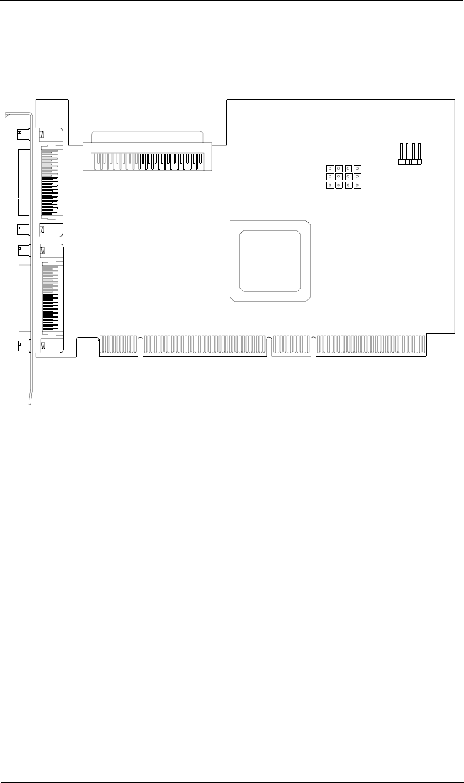
Figure 2-1 identifies the QLA12160 board components referenced throughout this
section.
Figure 2-1. QLA12160 Board Layout
2.3
Setting the SCSI Termination
Termination for the QLA12160 board is set automatically in most cases. You can
change the termination using the Fast!UTIL software (see section A.2.3).
Termination for the QLA12160 board also can be set using jumpers (see
section B.2).
2.4
SCSI Termination Power
The QLA12160 board supplies termination power to itself and to the SCSI bus. The
circuit is protected by a self-restoring fuse.
2.5
Installing the Device Activity Light
If the SCSI disk is assigned as drive C (boot drive), you can connect the device
activity light on the front panel of the PC to indicate boot drive activity. Connect the
J9
1
J2
J1
J6 J7J8
J3
SCSI LED
4
J5
ISP CHIP
333 3
DC8110402

2 – Hardware Installation Installation in the Computer
BC8151101-00 C 2-3
light to the J9 jumper block on the QLA12160 board (pins 1 and 4 are positive). If
your boot drive is an integrated device electronics (IDE) drive or connected to a
different adapter, you can connect an LED to the QLA12160 board jumper blocks
to show activity of devices connected to your QLA12160 board.
2.6
Installation in the Computer
If you changed the termination on the QLA12160 board, double-check the new
setting prior to installation.
Perform the following steps to install the QLA12160 board in your PC:
1. Check the motherboard and make any configuration changes necessary to
accommodate the QLA12160 board.
The QLA12160 board is self-configuring; however, some motherboards
require manual configuration. For example, some systems have a PCI
Device Configuration menu in the motherboard setup BIOS where you must
enable host adapter boards, bus master slots, and interrupt request (IRQ)
levels. If your motherboard supports triggering, use level triggering for the
QLA12160 board. See the documentation supplied with your computer, or
contact your computer dealer to determine whether or not your motherboard
requires configuration.
2. Power down the peripherals, then the computer.
3. Remove the computer cover and save the screws.
4. Choose any PCI bus slot that supports bus mastering. Most motherboards
automatically assign an IRQ level and interrupt line. If your motherboard
does not, you must assign the IRQ level and use interrupt line A for this slot.
NOTE:
■Some motherboards have two kinds of PCI bus slots: master
and slave. The QLA12160 board must be in a PCI bus master
slot. (Some motherboards share PCI bus master slots with
onboard devices; QLA12160 boards do not work in shared
slots.)
■If your board is labeled QLA12160/66, it can run in a 66-MHz
PCI slot.
❑QLogic recommends installing the QLA12160/33 in a
33-MHz PCI slot and the QLA12160/66 in a 66-MHz PCI
slot.
❑Installing a QLA12160/33 adapter in a 66-MHz PCI slot
forces the entire PCI bus to 33 MHz.
❑Installing a QLA12160/66 in a 33-MHz slot does not provide
the board with the performance benefits of a 66-MHz PCI
bus.

Installation in the Computer 2 – Hardware Installation
2-4 BC8151101-00 C
5. Unscrew and remove the slot cover. Retain the screw to use when you install
the QLA12160 board.
6. Place the QLA12160 board into the slot. Carefully press the board into the
slot until it seats firmly.
NOTE: QLA12160 boards are designed with the components on the
opposite side compared with non-PCI boards.
7. Secure the QLA12160 board with the slot cover screw.
8. Install the cable.
❑Internal: Connect the cable from the devices to the J3 connector on the
QLA12160 board.
❑External: Connect a SCSI cable from the devices to the J1 connector
and/or the J2 connector.
NOTE: If you are attaching an external device, you must provide your own
cable.
9. Carefully reinstall the computer cover. Insert and tighten the computer cover
screws.
10. Power up all external SCSI devices, then power up the PC and observe the
monitor. The BIOS lists all SCSI devices attached to the QLA12160 board.
For example:
Write down and store the SCSI device information for future use. You can
access the same information using Fast!UTIL (see appendix A). This
information is helpful when troubleshooting or installing other devices.
If there is no hard disk drive attached to your computer, a ROM BIOS NOT
INSTALLED message is displayed after the device listing.
When the information displayed on your monitor is correct (all installed devices are
listed with the correct SCSI ID, device type, etc.), congratulations! You have
successfully installed the QLA12160 board in your computer.
QLogic Corporation
PCI SCSI ROM BIOS Version X.XX
Copyright (C) QLogic Corporation 1999 All rights reserved.
Press <Alt-Q> for Fast!UTIL
Using IRQ number X
Device
Number
Device
Type
Adapter
Number
SCSI
ID
SCSI
LUN
Vendor
ID
Product
ID
Product
Revision
81 Disk 0 0 0 SEAGATE ST32550 7394

2 – Hardware Installation Installation Help
BC8151101-00 C 2-5
See the Software Installation Guide for the QLA12160 Board on the QLogic web
site http://www.qlogic.com/ for detailed instructions on how to install the QLA12160
board’s software drivers.
If the information displayed on your monitor is not correct and you have checked
the QLA12160 board’s configuration, see section 3 for troubleshooting information.
2.7
Installation Help
If your system has an IDE fixed disk device, be sure to program the system BIOS
to point to the appropriate boot drive. If your system does not have an IDE disk
device, the first bootable SCSI disk device configured (the one with the lowest SCSI
ID) is assigned device number 80 and is the boot device.
For a motherboard BIOS that does not support SCSI disk booting, you can use
settings in Fast!UTIL to select the system’s boot device attached to the QLA12160
board. If the boot device is a CD-ROM, see the CDROM boot setting in table A-1.
If the boot device is a disk, see section A.2.5 about selectable boot settings.
SCSI ID numbers must be unique; otherwise, the BIOS list of SCSI devices
displayed on your monitor is not correct. For example, if you give one of your devices
the same SCSI ID as the QLA12160 board, that device is listed for all SCSI IDs; or
if you have two devices with the same SCSI ID, only one of the devices is listed. If
the BIOS list is not correct, power down the computer and check the configuration.
Be sure to check the QLA12160 board, which uses SCSI ID 7. If you do not see
your device listed on the BIOS listing, see section 3.
If you do not have an IDE drive, set the motherboard BIOS parameters to None or
Not Installed. The ROM BIOS on the SCSI controller automatically configures the
SCSI peripherals.
If the QLA12160 board is on a SCSI bus with any single-ended peripheral device,
for example, a CD-ROM, the QLA12160 board automatically operates as a
single-ended, Ultra device. Consequently, all single-ended device restrictions apply
to the QLA12160 board, even though it is an LVD device (see table 3-1 and
appendix C).

Installation Help 2 – Hardware Installation
2-6 BC8151101-00 C

DC8151101-00 B 3-1
Section 3
Troubleshooting
3.1
Problems After Installation
There are three types of installation problems that can cause your QLA12160 board
to function incorrectly: hardware problems, system configuration problems, and
SCSI problems. This section provides itemized checklists to help you determine
why your QLA12160 board is functioning incorrectly.
NOTE: The latest versions of release notes, software drivers, flash BIOS, and
documentation are available on the QLogic web site,
http://www.qlogic.com/.
3.2
Hardware Problem Checklist
■Are all circuit cards installed securely in the PC?
■Are all cables securely connected to the correct connectors?
■Is the QLA12160 board installed correctly in the PC? Is it seated firmly in
the slot?
■Are all external peripherals properly powered up? See section A.3 for
information about displaying attached devices.
3.3
System Configuration Problem Checklist
■Is the motherboard configured properly (see section 2.6)? See the
documentation supplied with your computer, or contact your computer dealer
to determine whether or not your motherboard requires configuration.
■Is the disk drive partitioned correctly? If the system message Missing
Operating System or No ROM BASIC, System Halted is displayed, the disk
drive attached to the QLA12160 board is not partitioned in a format
compatible with the board. The proper geometry for use with the QLA12160
boards is the Microsoft standard.
❑Drives less than 1 GB are 64 heads, 32 sectors per track
❑Drives more than 1 GB are 255 heads, 63 sectors per track
If the drive is not formatted with this geometry, repartition and format the
drive using the DOS FDISK and FORMAT utilities.

SCSI Problem Checklist 3 – Troubleshooting
3-2 DC8151101-00 B
3.4
SCSI Problem Checklist
■Is the SCSI bus termination for the QLA12160 board set correctly (see
appendixes A and B)?
■Is the termination for all devices on the SCSI bus set correctly?
■Were all SCSI devices powered up before you powered up the PC?
■Does each device have a unique SCSI ID? Each device must have a unique
ID between 0 and 15. The QLA12160 board is set to SCSI ID 7 at the factory.
■Are the cable lengths within limits? Be sure that the total length for cables
connected to the QLA12160 board does not exceed the length listed in
table 3-1.
Table 3-1. Maximum Cable Length
Board and Mode Cable Length
QLA12160
point-to-point
15 nodes
single-ended Ultra mode
82 feet (25 meters)
39 feet (12 meters)
9.8 feet (3 meters)a
4.9 feet (1.5 meters)b
Table Notes
If you are mixing Ultra and non-Ultra SCSI devices, the total cable length cannot exceed the
maximum cable length established for Ultra SCSI devices.
aFor four or fewer devices connected to the board.
bFor up to six devices connected to the board.

DC8151101-00 C A-1
Appendix A
Fast!UTIL
A.1
Introduction
This appendix provides detailed configuration information for advanced users who
want to customize the configuration of the QLA12160 board and the connected
devices.
The QLA12160 board is configured at the factory to provide maximum performance.
When your board is operating at maximum performance, it may not be 100%
compatible with some older SCSI-1 devices. If you are using a SCSI-1 device, see
section A.5 for more information.
The board can be configured using Fast!UTIL. To access Fast!UTIL, press ALT+Q
during the QLA12160 board BIOS initialization (it may take a few seconds for the
Fast!UTIL menu to appear). If you have more than one QLA12160 board, Fast!UTIL
prompts you to select which board you want to configure. After changing the settings,
Fast!UTIL reboots your system to load the new parameters.
CAUTION! When the configuration settings are incorrect, the QLA12160 board
does not function properly.
The following sections describe the Fast!UTIL options.
A.2
Configuration Settings
The first selection on the Fast!UTIL Options menu is Configuration Settings.
These settings configure SCSI devices and the QLA12160 board to which they are
attached.

Configuration Settings A – Fast!UTIL
A-2 DC8151101-00 C
A.2.1
Host Adapter Settings
From the Configuration Settings menu in Fast!UTIL, select Host Adapter
Settings. Default settings for the QLA12160 host adapter board are listed in
table A-1 and described in the following paragraphs.
■Host adapter BIOS. When this setting is Disabled, the ROM BIOS on the
QLA12160 board is disabled, freeing space in upper memory. The RAM
BIOS and other drivers still recognize the QLA12160 board. Do not disable
this setting when you are booting from a SCSI disk drive attached to the
QLA12160 board. The default is Enabled (ROM BIOS on the QLA12160
board is enabled).
■PCI bus DMA burst. When this setting is Enabled, burst transfers are
performed. When this setting is Disabled, data is transferred in nonburst
mode, with each cycle initiated by a new address phase. The default is
Enabled.
■CDROM Boot. When this setting is Enabled, the ROM BIOS boots from the
attached SCSI CD-ROM when a bootable compact disk is installed. If no
bootable CD-ROM is found, the system boots from the first bootable SCSI
drive. When this setting is disabled, the ROM BIOS does not boot from the
CD-ROM. The default is Disabled.
■Adapter Configuration
❑Auto. The ROM BIOS automatically configures the QLA12160 board to
match any SCSI device attached to the board and selects optimum
performance. The default is Auto.
❑Manual. You can control the configuration settings for each SCSI device
and have the option of running Autoconfigure. See section A.2.4 to have
Fast!UTIL configure the devices.
NOTE: Changing any value can cause performance problems or
incorrect device operation.
Table A-1. Host Adapter Settings
Setting Options Default
Host adapterBIOS Enabled, Disabled Enabled
PCI bus DMA burst Enabled, Disabled Enabled
CDROM Boot Enabled, Disabled Disabled
Adapter Configuration Auto, Manual, Safe Auto
Drivers load RISC code Enabled, Disabled Enabled
>4 Gbyte Addressing Enabled, Disabled Disabled
Fast Command Posting Enabled, Disabled Enabled

A – Fast!UTIL Configuration Settings
DC8151101-00 C A-3
❑Safe. All optimal configuration settings are disabled and all attached
devices work in minimal configuration (narrow, asynchronous mode).
NOTE: Safe mode is primarily for troubleshooting SCSI devices that
are not functioning properly during normal system operation.
■Drivers Load RISC Code. When this setting is Enabled, the QLA12160
board uses the RISC firmware that is embedded in the software driver. When
this setting is Disabled, the software driver loads the latest version of RISC
firmware found on the system. The default is Enabled.
NOTE: The driver being loaded must support this setting; otherwise, the
result is the same as Disabled regardless of the setting. Leaving
this option Enabled guarantees a certified combination of software
driver and RISC firmware.
■>4 Gbyte Addressing. Enable this setting when your system has more
than 4 GB of RAM available. The default is Disabled.
■Fast Command Posting. When this setting is Enabled, command execution
time is decreased by minimizing the number of interrupts. The default is
Enabled.
A.2.2
SCSI Device Settings
After changing the host adapter settings for the QLA12160 board, you can modify
device parameters for SCSI devices connected to the board. From the
Configuration Settings menu in Fast!UTIL, select SCSI Device Settings. The
settings are linked to the device’s SCSI ID (0–15). If you make changes, be sure
that the SCSI ID matches the settings of the device you want to change. Select
Scan SCSI Bus from the Fast!UTIL Options menu to see the SCSI IDs assigned
on your system (see section A.3).
NOTE: The Adapter Configuration setting in the Host Adapter Settings (see
section A.2.1) controls which device settings you can change.
The options and defaults for SCSI device settings are listed in table A-2 and
described in the following paragraphs.
Table A-2. SCSI Device Settings
Setting Options Default Adapter Configuration
Setting
Disconnects OK Yes, No Yes Auto, Safe, Manual
Check Parity Yes, No Yes Auto, Safe, Manual
Enable LUNs Yes, No Yes Auto, Safe, Manual
Enable PPR Yes, No Yes Manual

Configuration Settings A – Fast!UTIL
A-4 DC8151101-00 C
NOTE: These settings apply to each SCSI ID individually.
■Disconnects OK. When set to Yes, the device is notified that it can optionally
disconnect from the host adapter. When the drive is ready to continue
executing the command, it must re-establish the link through a reconnect
cycle. When set to No, disconnects are not allowed. The default is Yes.
If you have more than one device attached to the QLA12160 board, set
Disconnects OK to Yes for best performance.
■Check Parity. When set to Yes, odd parity is checked and passed to the
SCSI FIFO when data is received from the SCSI bus. When set to No, the
received SCSI parity is ignored and odd parity is generated for the SCSI
FIFO. The default is Yes.
■Enable LUNs. When set to Yes, multiple LUNs are supported. When set to
No, multiple LUNs are not supported. LUN support is typically required for
CD-ROM changers or RAID boxes that use LUNs to map drives. The default
is Yes.
■Enable PPR. When set to Yes, the QLA12160 board attempts to negotiate
for parallel protocol request (PPR) transfers. When set to No, the QLA12160
board does not negotiate for PPR transfers. The default is Yes.
■Enable Device. When set to Yes, the system BIOS recognizes the device
at this SCSI ID. When set to No, the system BIOS ignores the device at this
SCSI ID. The default is Yes.
■Negotiate Wide. When set to Yes, the device supports 16-bit, wide (68-pin
cable) SCSI data transfers. When set to No, the device supports only 8-bit
(50-pin cable) SCSI data transfers. The default is Yes.
Enable Device Yes, No Yes Manual
Negotiate Wide Yes, No Yes Manual
Negotiate
Synchronous Yes, No Yes Manual
Tagged Queuing Yes, No Yes Manual
Sync Offset 00, 02, 04, 06, 08, 10,
12, 14, 16, 18, 20, 22,
24
24 Manual
Sync Period 9, 10, 12, 25, 40 9Manual
Exec Throttle 1, 4, 8, 16, 32, 64,
128, 255 16 Auto, Safe, Manual
Table A-2. SCSI Device Settings (Continued)
Setting Options Default Adapter Configuration
Setting

A – Fast!UTIL Configuration Settings
DC8151101-00 C A-5
■Negotiate Synchronous. When set to Yes, the QLA12160 board negotiates
synchronous data transfers with the device. When set to No, the QLA12160
board uses only asynchronous data transfers. The default is Yes.
■Tagged Queuing. When set to Yes, the device queues multiple commands.
When set to No, multiple queues are not supported. The default is Yes.
■Sync Offset. This setting specifies the maximum number of requests (REQ)
that can be sent during a synchronous data transfer before an acknowledge
(ACK) is received. Valid values for this field are 00, 02, 04, 06, 08, 10, 12,
14, 16, 18, 20, 22, and 24. The default is 24.
■Sync Period. This setting specifies the minimum REQ/ACK period, in 4-ns
increments, for a synchronous data transfer. Valid values for this field are 9
(160 MBps, Ultra3), 10 (80 MBps, LVD), 12 (40 MBps, Ultra), 25 (20 MBps,
fast), and 40 (12.5 MBps). The default is 9.
■Exec Throttle. This setting specifies the maximum number of commands
executing on any one port. When a port’s execution throttle is reached, no
new commands are executed until the current command finishes. Valid
values for this field are 1, 4, 8, 16, 32, 64, 128, and 255. The default is 16.
A.2.3
SCSI Bus Settings
The options and defaults for SCSI bus settings are listed in table A-3 and described
in the following paragraphs.
■Host adapter SCSI ID. This setting defines the SCSI ID of the QLA12160
board. The default is 7.
■SCSI bus reset. When this setting is Enabled, the SCSI bus is reset at
system power up. Disable this setting to prevent unwanted SCSI bus resets
when you have two or more host adapter boards on the SCSI bus. The
default is Enabled.
■SCSI bus reset delay. After resetting the SCSI bus, the firmware does not
initiate any SCSI activity for the number of seconds specified in this setting.
The default is 5 seconds.
Table A-3. SCSI Bus Settings
Setting Options Default
Host adapter SCSI ID Enabled, Disabled Enabled
SCSI bus reset Enabled, Disabled Enabled
SCSI bus reset delay 0–15 seconds 5 seconds
SCSI Termination Auto, Enabled, Disabled,
High Only Auto

Configuration Settings A – Fast!UTIL
A-6 DC8151101-00 C
■SCSI termination
Termination for the QLA12160 board can be set in one of three ways:
❑Automatic (default)
❑Manual (through Fast!UTIL)
❑Jumpers
NOTE: The last SCSI device on each end of the SCSI bus must be
terminated.
The QLA12160 board is a dual-port host adapter. Each port is a separate
SCSI bus and must be terminated independently. The port one and two
connectors are listed in table A-4.
The following text explains automatic and manual termination. See
section B.2 for jumper termination instructions.
❑Auto. SCSI termination requirements are sensed by the board and set
automatically. The default is Auto.
With QLA12160 boards, the Auto setting assumes that port one is at one
end of the SCSI bus and enables termination for port one. If you are
using a single port-one connector, the Auto setting assumes that port
one is at the end of the SCSI bus and enables termination for port one.
If you have devices connected to both port one connectors, the Auto
setting disables termination for port one.
❑Enabled. This setting overrides termination requirements sensed by the
board, assumes that the selected port is at one end of the SCSI bus,
and enables termination.
❑Disabled. SCSI termination is disabled. This setting overrides
termination requirements sensed by the board. Use this setting when J1,
J2, or J3 is not at one end of the SCSI bus. For example, use this setting
when you have wide devices daisy chained to the QLA12160 J1, J2,
or J3 connector with a single cable and the J1, J2, or J3 connector is not
at the end of the cable.
❑High Only. High termination is enabled. This setting overrides termination
requirements sensed by the board.
Use this setting for the QLA12160 board’s port one (J1 or J3) when you
have a wide device connected to one connector and a narrow device
Table A-4. QLA12160 Ports
Port QLA12160 Port
Connector
One J1 and J3
Two J2

A – Fast!UTIL Configuration Settings
DC8151101-00 C A-7
connected to the other connector. Use this setting for the QLA12160
board’s port two (J2) when the port two connector is not at one end of
the SCSI bus and you have narrow devices at one end of the bus and
wide devices at the other end.
A.2.4
Autoconfigure SCSI Devices
NOTE: You must set the Adapter Configuration setting in Host Adapter Settings
to Manual (see section A.2.1) to use Autoconfigure; otherwise, all changes
made with Autoconfigure are reset when your system is rebooted.
The QLA12160 board is designed to sense and configure the devices connected
to your board. When Adapter Configuration is set to Manual, the Autoconfigure
option allows you to control when the bus is scanned and configured. Select the
Autoconfigure SCSI Devices option from the Configuration Settings menu to
scan devices on the SCSI bus. Set the following options, based on the capabilities
of each device:
■Disconnects
■Enable LUN Support
■Enable PPR
■Enable Device
■Negotiate Wide
■Negotiate Synchronous
■Tagged Queuing
■Sync Period
The settings are displayed in the SCSI Device Settings window. Use the arrow
keys to change settings. See section A.2.2 for more information about SCSI Device
Settings and see section A.2.1 for Host Adapter Settings.
If you use Autoconfigure to configure your system, run Fast!UTIL and select
Autoconfigure SCSI Devices after adding or reconfiguring devices attached to the
QLA12160 board.
A.2.5
Selectable Boot Settings
The Selectable Boot Settings option is accessed from the Configuration Settings
menu. When this option is Enabled, you can select the SCSI ID (0–15) from which
you want to boot. Once enabled, this option forces the system to boot on the selected
SCSI drive, ignoring any IDE drives attached to your system. When this option is
Disabled, the system looks for an IDE drive from which to boot. When an IDE drive
is not found, the system looks for the first bootable SCSI drive. When this option is
disabled, SCSI Boot ID and SCSI Boot LUN parameters have no effect.
NOTE: This option applies only to disk devices, not to CD-ROMs, tape drives, or
other nondisk devices.

Scan SCSI Bus A – Fast!UTIL
A-8 DC8151101-00 C
A.2.6
Restore Default Settings
The Restore Defaults option from the Configuration Settings menu restores the
QLA12160 board default settings, which are displayed in SCSI Device Settings.
Use the arrow keys to change settings. See section A.2.2 for more information about
SCSI Device Settings and see section A.2.1 for Host Adapter Settings.
A.2.7
Raw NVRAM Data
This option displays the adapter’s nonvolatile random access memory (NVRAM)
contents in hexadecimal format. This is a troubleshooting tool; you cannot modify
the data.
A.3
Scan SCSI Bus
This option scans the SCSI bus and lists all connected devices by SCSI ID.
Information about each device is listed, for example, vendor name, product name,
and revision. This information is useful when configuring your QLA12160 board and
attached devices.
A.4
SCSI Disk Utility
This option scans the SCSI bus and lists all the connected devices by SCSI ID. You
can select a disk device and perform a low-level format or verify the disk media.
CAUTION! Performing a low-level format destroys all data on the disk.
A.5
Using SCSI-1 Devices
The QLA12160 board is configured at the factory with default parameters that
provide maximum performance. When the board is operating at maximum
performance, it may not be 100% compatible with some older SCSI-1 devices.
If the SCSI-1 device attached to the QLA12160 board is not functioning correctly,
you can turn off some high-performance parameters for maximum compatibility.
Follow these steps:
1. When you power up the system, press CTRL+Q to access Fast!UTIL.
2. Select Configuration Settings from the Fast!UTIL Options menu.

A – Fast!UTIL Using SCSI-1 Devices
DC8151101-00 C A-9
3. Select SCSI Device Settings. A window displays the settings for each SCSI
device. Make the following changes for each SCSI ID to which a SCSI-1
device is assigned.
a. Change the Negotiate Wide setting to No.
b. Save the parameters.
c. Exit Fast!UTIL.
d. Reboot the system.
4. If your SCSI device still does not function correctly, repeat steps 1 through 3.
In step 3, change the following parameters to No, one at a time, rebooting
after each change to check your system’s performance.
a. Negotiate Synchronous
b. Check Parity
c. Enable LUNs
d. Disconnects OK
When the system operates correctly, do not change more parameters.
If you’ve changed all parameters in steps 3 and 4 and your system still does not
function correctly, follow these steps.
1. When you power up the system and the BIOS banner appears, press ALT+Q
to access Fast!UTIL.
2. Select Configuration Settings from the Fast!UTIL Options menu.
3. Select Host Adapter Settings.
4. Change the PCI Bus DMA Burst setting to Disable.
5. Exit Fast!UTIL.
6. Reboot the system.
If your devices still do not function properly, change the Adapter Configuration
settings in the Host Adapter Settings to Safe (see section A.2.1).

Using SCSI-1 Devices A – Fast!UTIL
A-10 DC8151101-00 C

DC8151101-00 C B-1
Appendix B
SCSI Termination
B.1
Setting the SCSI Termination
The first and last physical SCSI devices on each end of the SCSI bus must be
terminated.
Termination is set automatically through Fast!UTIL (see section A.2.1). The
QLA12160 board offers the additional option of terminating with jumpers (see
section B.2).
Some cables have multiple connectors for connecting several devices to one of the
board’s connectors. If the board uses a connector that is not on either end of the
cable, then the board is not at one end of the SCSI bus and you need to change
the termination setting.
The following sections describe how to set termination for the QLA12160 board.
The text and illustrations describe multiple SCSI devices daisy chained onto a single
connector on the board. When daisy chaining narrow and wide SCSI devices,
always have a wide SCSI device at the end of the chain.
NOTE: QLogic recommends using external termination in system configurations
with multiple initiators that share the same SCSI bus (such as in Microsoft
cluster configurations). External termination ensures proper device
operation during power cycles. When external termination cannot be
provided, terminate all host bus adapters using jumpers (see section B.2).
B.2
Termination (Jumpers) for the QLA12160
The QLA12160 board comes from the factory with jumpers on pins 1–2 of J5, J6,
J7, and J8; these settings allow automatic termination (see section A.2.1).
Moving the jumpers on J5 and J6 on the QLA12160 board manually sets the
termination for port one. Moving the jumpers on J7 and J8 on the QLA12160 board
manually sets the termination for port two (see figure B-1). Settings made with these
jumpers override all Fast!UTIL or automatic termination settings.
Termination (Jumpers) for the QLA12160 B – SCSI Termination
B-2 DC8151101-00 C
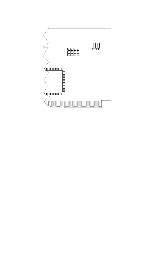
The QLA12160 board jumper block is illustrated in figure B-1.
.
Figure B-1. QLA12160 Jumper Termination
The following paragraphs give manual termination instructions.
■Termination disabled. Removing the jumpers from J5 and J6 disables
termination for port one. Use this configuration for wide devices daisy
chained to J1 and J3 with a single cable, or when J1 or J3 is not at the end
of the cable. Removing the jumpers from J7 and J8 disables termination for
port two. Use this configuration for wide devices daisy chained to J2 with a
single cable, and J2 is not at the end of the cable.
■Termination enabled. Putting jumpers on pins 2–3 of J5 and J6 enables
termination for port one. Use this setting when a wide device is connected
to J1 or J3. Putting jumpers on pins 2–3 of J7 and J8 enables termination
for port two. Use this setting for a wide device connected to J2.
■High only. Putting a jumper on pins 2–3 of J5 and removing the jumper from
J6 enables high termination for port one. Use this setting for a wide device
connected to one connector and a narrow device connected to the other.
ISP CHIP
J9
1
J6J7J8 4
J5
3333
SCSI LED
DC8110402
QLA12160 (DC8110402)

DC8151101-00 C C-1
Appendix C
Specifications
Table C-1. QLA12160 Board Operating Environment
Environment Minimum Maximum
Operating temperature 0°C (32°F) 55°C (131°F)
Storage temperature –20°C (–4°F) 70°C (158°F)
Relative humidity (noncondensing) 10% 90%
Storage humidity (noncondensing) 5% 95%
Table C-2. QLA12160 Board Specifications
Type Specification
Host bus Conforms to PCI Local Bus Rev. 2.2 specification
SCSI standard ANSI X3.131-1994 SCSI-2
ANSI X3T10/1071D SCSI-3 Fast-20 (Ultra SCSI)
ANSI X3T10/1142D Fast-40 draft (Ultra2 SCSI)
ANSI T10 project 855D, Information Technology—SCSI-3 Parallel
Interface (SPI)
ANSI T10 project 1142D, Information Technology—SCSI Parallel
Interface-2 (SPI-2)
ANSI T10 project 1302D, Information Technology—SCSI Parallel
Interface-3 (SPI-3)
SCSI data handling Synchronous:
Wide and Ultra SCSI (40 MBps)
Narrow Ultra SCSI (20 MBps)
Ultra2, LVD SCSI (80 MBps)
Ultra3, LVD SCSI (160 MBps)
Wide and fast SCSI (20 MBps)
Narrow fast SCSI (10 MBps)
Narrow SCSI (5 MBps)
Asynchronous (all boards)
CPU Embedded RISC processor
Host data transfer 64-bit, bus master DMA data transfers to 264 MBps
Transfer counter 24-bit
RAM 128 KB of static RAM
FIFO 128-byte command DMA FIFO; 512-byte data DMA FIFO
with threshold control
Electrical drivers Single-ended and LVD

C – Specifications
C-2 DC8151101-00 C
Connectors 68-pin, high-density, internal SCSI-2 connector (port one)
Two 68-pin, external VHDCs
Form factor 17.78cm × 10.67cm (7.0" × 4.2")
Operating power 5 volts @ 3 ampere
Table C-2. QLA12160 Board Specifications (Continued)
Type Specification
