Q3 Innovations RH-SM Radar Detector X, Ku, K and Ka Band User Manual RadarHAWK SM Manual DRAFT
Q3 Innovations, LLC Radar Detector X, Ku, K and Ka Band RadarHAWK SM Manual DRAFT
Users Manual
3
2
1. Important Cautions for Use this Unit in Safety
2. Controls, Indicators and Connections
3. Accessories
4. Installation
5. Feature
6. How to Use
7. Understanding Radar Detector
8. Troubleshooting
9. Specification
Read this book and understand how to use the RadarHAWK™
SM. Keep this book and refer in each case.
Follow the cautions in this book for safety use of this unit, or it
may lead accidents.
Locate this unit on the passenger side windshield.
- If locate on the driver side windshield, it obscures the
driver from view.
Don't get the unit wet. Electrocution Hazard. Death or
Serious Injury can result.
Don't operate this unit during driving.
Don't open the housing case of this unit.
Stop the use of this unit if it has a fever, strange odor,
emitting smoke.
Use under the temperature of –10 ~ +60 degree Centigrade.
- Don't leave the unit in car under high/low temperature.
Result the failure.
Before leaving your vehicle, always remember to conceal
the unit in order to reduce the possibility of break-in and theft.
Don’t put impact shock on the unit.
Under high temperature, this unit can have a fever.
- Don’t touch until the unit gets enough cold. Get burned.
Obey the traffic laws.
Don't use RadarHAWK™ SM if the unit is illegal in your area.
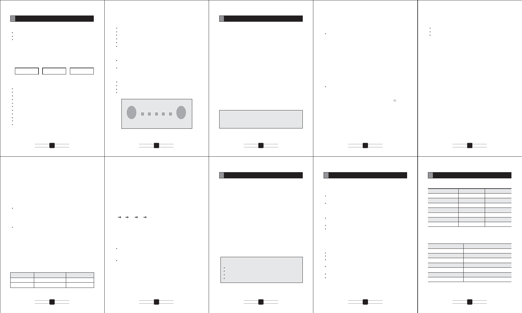
<Windshield mounting>
When you set the unit on the windshield, triangle two-sided
tape becomes unnecessary. Keep it in case you change the
installation location.
1. Make sure the suction cups and your windshield are clean.
2. Attach provided rubber
foot onto bracket.
3. Push the bracket to stick the
rubber cups.
4. Attach the bracket to the
bracket socket on the bottom
side of the detector unit.
5. Fix the detector unit onto the
windshield. Set the radar rear
side in the direction of travel.
Adjust the angle of the unit
to keep in the horizontal
position. If necessary,
adjust the
bracket
screw to
change the
angle. After the
angle becomes on the
level, tighten the screw
firmly.
6. Plug the power cord into the detector unit.
7. Plug the cigarette light adaptor in the power cord into your
vehicle's cigarette lighter socket.
<Dashboard Mounting>
When you set the unit on the dashboard, suction cups and
rubber foot become unnecessary.
Keep them in case you change the installation location.
1. Place the detector unit on the dashboard to find a location
where the unit has a clear, level view of the road.
2. Remove the paper backing
from one (1) side of the triangle
two-sided tape and attach the
sticky side of two-sided tape
on the bracket.
3. Attach the bracket to the
bracket socket on the bottom
side of the detector unit.
4. Remove the paper backing
from another side of the
triangle two-side tape
and attach to the location
yousettheunitonthe
dashboard. Pay attention
to set the radar rear side
in the direction of travel.
If necessary, adjust the
bracket screw to change
the angle. After the angle
becomes on the level,
tighten the screw firmly.
5. Plug the power cord into the detector unit.
6. Plug the cigarette light adaptor on the power cord into your
vehicle's cigarette lighter socket.
RadarHAWK™ SM
RadarHAWK™ SM
Note and precautions for solar cell and built-in battery;
Plug the provided cigarette cable to charge the built-in
battery for the initial use of about 10 days driving.
5 hours charging by provided cigarette cable fully
charges the built-in battery.
Solar battery is aimed to support the built-in battery, and
only the solar cell can not charge the built-in battery
after RadarHAWK™ SM gives battery alert.
Plug the provided cigarette cable to charge the built-in
battery if RadarHAWK™ SM gives battery alert.
Solar battery can charge built-in battery even under
power OFF.
Stand-by time of detector with full-charged battery is
approximately 19 hours, but running time depends on
the detection/warning condition.
High/low temperature can effect on the charging time.
Solar battery cannot charge adequate electricity under
rainy/cloudy weather, during nighttime, in a basement
park, under sunshade, and etc. where give inadequate
sunlight.
Solar battery shall be exposed to sunlight in its whole
area, or cannot charge adequate electricity.
USER MANUAL
Introduction
Important Cautions for Use this Unit in Safety
1
Installation
4
Controls, Indicators and Connections
2
Accessories
3
Table of Contents
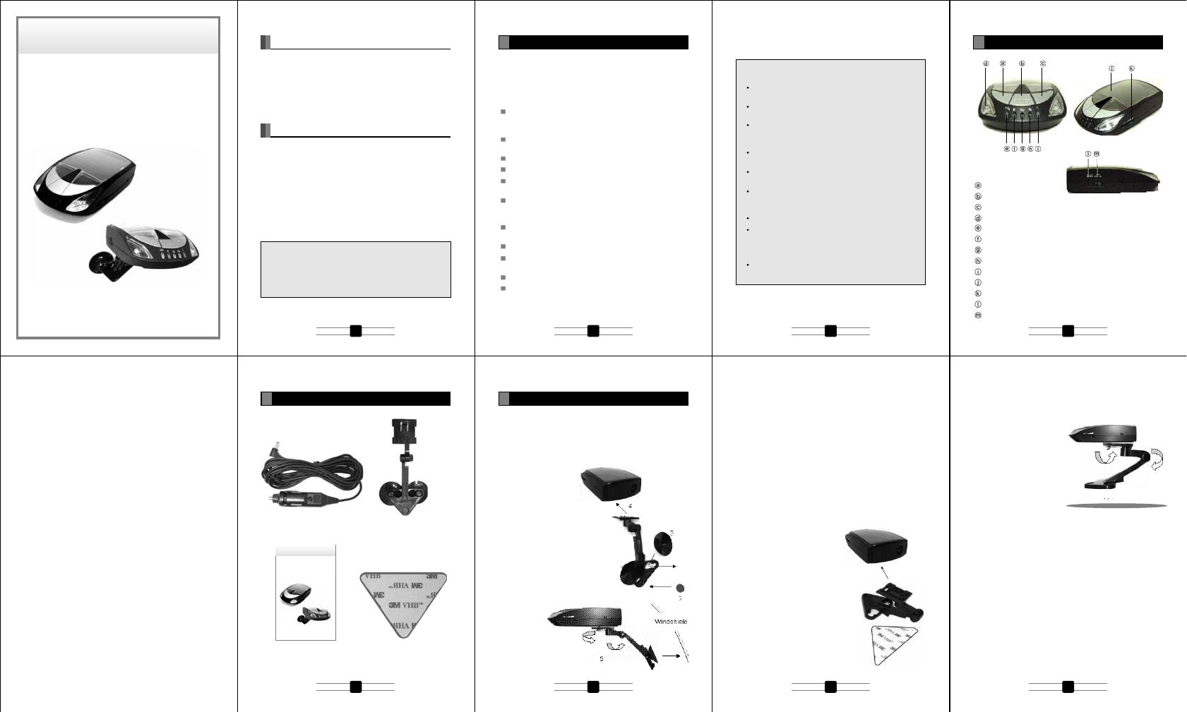
APS Button
BAND Button
CITY Button
Warning Light : 2pcs (left and right)
P/X Alert LED
K Alert LED
Ku Alert LED
Ka Alert LED
Laser Alert LED
Solar Cell
Volume Controller
12V DC Power Jack
Power Switch
Triangle two-sided tape
12V DC power cable Bracket, 2 (two) suction cups and
rubber foot
User manual
Dashboard
4
1 2 3 4
5 6 7 8
ALL-BAND (X, K, Ka) ULTRA HIGH-PERFORMANCE
SOLAR-POWERED
RADAR/LASER DETECTOR
Important: The RadarHAWK™ SM is not designed to help
you disobey the law, and its manufacturer doesn’t take
responsibilities of any speeding violations cased with
using the RadarHAWK™ SM. A defensive driver always
obeys the posted speed limit and driving methods.
Congratulations on your purchase of one of the world’s most
sophisticated solar radar/laser detectors. The RadarHAWK™
SM is a completely integrated radar/laser detector which
responds not only to all the radar guns in use today, but also to
the other latest development in speed monitoring devices - the
laser gun.
RadarHAWK™ SM
USER MANUAL
ALL-BAND (X, K, Ka) ULTRA HIGH-PERFORMANCE
SOLAR-POWERED
RADAR/LASER DETECTOR
Auto mute and Auto DIM control
The unit alert with reduced audio alarms and with reduced LED
brightness for continuously detected signals. When an alert is
constantly reported for radar/laser signal, the unit will
automatically reduce the audio sound level and the LED
brightness
AUTOMUTE
- Detected 3 level signal (strong signal strength) : Audio
sound level will reduce after 10sec.
- Detected 1~2 level signal (low~middle signal strength) :
Audio sound level will reduce after 30sec.
AUTODIM
- Detected 3 level signal(strong signal strength) : LED
brightness will reduce after 5sec.
- Detected 1~2 level signal(low~middle signal strength): LED
brightness will reduce after 10sec.
Sensitivity control (City/Highway mode)
Press the CITY button repeatedly each time to toggle the
“CITY” or “HIGHWAY” mode. The factory default is the
HIGHWAY mode. CITY mode starts with 1 beep and the
HIGHWAY with 2 beeps.
TEST mode
Press and hold the BAND button for longer than 3 seconds and
the unit will demonstrate how it operates when radar and laser
signals are detected. The unit will displays every visual alert
message with the corresponding unique audio tone for its own.
After the tutorial sequence is all done the screen will stay at the
all-indicator-on status for 5 seconds and gets back to the
stand-by mode.
XK Ku Ka LASER
BAND ON/OFF
Press BAND button to off (or on) X band (9.900GHz/10.525GHz).
Automated function/features
Protection against VG-2
The unit must be completely invisible to (undetectable by) the
VG-2 interceptor
Alert Priority
The unit must report on the FIFO (first in first out) basis.
However, when there is laser signals detected at a time, it must
report by the following priority rule:
- Laser signal
- Radar signal
RadarHAWK™ SM detects radar signals by buzzer alert
and indicator while driving. The buzzer alert and indicator
warning lighting change in accordance with increasing/de-
creasing of the radar signals.
Frequency of radar/laser signals
X band : 9.900GHz, 10.525 GHz
Ku band: 13.450GHz
K band : 24.125 GHz, 24.150GHz
Super wide Ka band : 33.400~36.000GHz.
Laser : 905nm
Police Speed Control Machine
RadarHAWK™ SM detects Radar transmitter measures
the speed of vehicle. Automatically the transmitter takes
the photo of the violation speeding vehicle.
This system has variety like Stationary Installation Type, Gun
Type and Car Portable Type.
Note
Radar detector may detect interruption signals such from;
Automatic door
Wireless CCTV system
Vehicle monitor system
Mobile phone radiation base
Confirm the following points if any problem found;
Trouble of power-on operation
Battery exhaustion/battery shutoff - Recharge by the
Cigarette plug cable.
Power switch is off - turn on the power switch.
Trouble of battery recharge
Sunlight is not enough - Confirm it can be rechargeable by
the Cigarette plug cable.
Fuse short - Change the fuse of cigarette plug.
Duration of rechargeable battery life - Use the unit by the
Cigarette plug cable.
Trouble of sound
No Sound
Power switch is off - turn on the power switch.
Setting of the sound is small - Change the setting.
Band function is off - press the Band button and change the
mode.
City mode is on - press the City/Highway button and change
to the Highway mode.
The police transmitter doesn't use the radar system.
The police transmitter is power-off.
Main Specification
Detection format Dual conversion superheterodyne
Operating voltage 12V DC (max 16V DC)
Rechargeable battery built in 3.6V, 400mA Ni/Cd battery
Operating temperature -10 to +60 degree C
Storage temperature -20 to +85 degree C
Stand-by time appx. 19hours with full-charged battery
Dimension W x D x H (mm) 72 x 122 x 32.2
sg041.xppathgieW
Band and Frequencies
Band Frequency Tolerance
X band 9.900GHz +/-25MHz
10.525GHz +/-25MHz
Ku band 13.450GHz +/-25MHz
K band 24.125GHz +/-100MHz
24.150GHz +/-100MHz
Superwide Ka band 34.700GHz +/-1300MHz
Laser 905nm +/-50nm
Power connection
Slide the power switch forward the display to turn the unit on.
If the unit has low battery status, Plug the adapter of the power
cord (12V DC) into the lighter in your vehicle and the pin at the
other side of the power cord into the power jack of the unit.
Start & Preamble
Slide the power switch forward the display to turn the unit on.
When powered on, the unit will beep and illuminate (blinking)
all the indicators. After preamble the unit will start flashing the
power indicator.
Low battery alert
The low battery alert will appear for 5sec when the battery
voltage is low level. This will repeat every 10 minutes until no
battery power remains and the radar detector shuts off.
“PW/X” LED will blink to alert low battery. Other LEDs are all off
during alert.
Note : We suggest keeping the power cord readily
available. If your batteries are drained, the cord will allow
you to continue using your radar detector until you
recharge the batteries.
APS (Automatic Power Save)
Basic function
If there is not a detected vibration signal for 5sec, The sound is
muted and LED brightness is reduced to 50% when there is a
detected radar/laser signal at that time.
Press the APS button repeatedly each time to toggle the APS
ON or APS OFF mode. The factory default is the APS ON
mode. The APS ON mode starts with 1 beep and APS OFF
mode starts with 2 beeps.
When the unit operates in the APS ON mode – [P/X] LED is
blinking with green color, but If there is not a detected vibration
signal for 5sec, [P/X] LED is blinking with red color.
When the unit operates in the APS OFF mode, [P/X] LED is
always blinking with red color. APS function should be
operated both in the +12V LINE MODE and BATTERY MODE.
Sensitivity adjustment
There is a piezo vibration sensor function added to the circuit.
The sensitivity control operation is as follows;
1. Sensor Sensitivity: High - Middle – Low (3 steps) Factory
default is MIDDLE (for low-vibration sedan car)
2. Press and hold APS button for three (3) seconds to enter
sensor sensitivity control mode (1 beep).
3. Select HIGH or MIDDLE or LOW using the APS button
(short press), then press and hold APS button again for
three (3) seconds to store and exit this mode.
4. You can select the mode with the warning lamp LED (blue)
display as follows.
High: left - ON, right - ON
Middle: left - ON, right - OFF
Low : left - OFF, right - ON
APO (Automatic Power Off)
To conserve battery power, the unit will automatically shut off
when there is not a detected vibration signal for 3minute,
- APO function operates both APS on and off mode.
- APO function should be operated under alerting.
- APO function should be operated both in the +12V LINE
MODE and BATTERY MODE.
To conserve battery power, MCU operate into Idle mode when
the unit is shut off. If there is a detected vibration signal, the
unit will turn on to resume the detection.
Memory retention
The unit keeps some of the operation modes in its memory
even after the unit is powered off, so that the unit can reboot
the same user settings when it’s turned on again. They are;
- APS on/off mode
- BAND on/off mode
- City/Highway mode
- Sensitivity adjustment (High/Middle/Low)
Volume control
Rotate the volume controller at the front anti-clockwise to
increase the audio level and clockwise to decrease. The
maximum audio level must be 85 +/- 5dB when measured at
the distance of 10cm from the buzzer.
Specication
9
Troubleshooting
8
Understanding Radar Detector
7
How to Use
6
Mode X/Ku Band K /Ka Band
Highway Full sensitivity Full sensitivity
City Reduce 20% Reduce 10%
User interface keys
A power switch at the left of the unit.
A volume controller at the right of the unit.
Three function buttons on the top of the unit:
APS/SENS : APS on/off (on-1beep, off-2beep by short
press), default APS on
Press SENS to set APS sensitivity
BAND : X band (9.900GHz/10.525GHz) on/off(on-1 beep,
off-2 beep), default BAND on
CITY : City/Highway(City-1beep, Highway-2beep), default
HIGHWAY
Main features
Detects all radar/laser bands
Undetectable by VG-2
360 degree laser coverage
LED display
Highway/City mode (Detection sensitivity selection)
Auto mute function
Auto Dim (LED brightness)
APS (Auto Power Save) on/off
APO (Auto Power Off)
Low battery alert
Retains memory on previously set operation modes after
power off
Test mode to demonstrate operations
Mounts on windshield and dashboard
Operates on the battery or a 12V power adapter
Rechargeable by solar cell
X Band ON/OFF
Built in rechargeable battery (NIMH AAA2/3 400mA@3.6V)
LED Display
Warning LED 2pcs : Lamp type LED, Blue color / left and
right side
PW/X : chip LED, dual color(Green/Red)
- APS on mode : Green blinking
- APS off mode : Red blinking
- X band Alert : Green on
K : Red color
Ku : Green color
Ka : Yellow color
Laser : Red color
Feature
5
APS/SENS BAND/TEST CITY/HIWAY
15 16 17 18
10
14
911 12 13
P/X K Ku Ka L
GNINRAWGNINRAW

FCC Compliance Statements
Note: This equipment has been tested and found to comply
with the limits for a Class B digital device, pursuant to part 15
of the FCC Rules. These limits are designed to provide
reasonable protection against harmful interference in a
residential installation. This equipment generates, uses
and can radiate radio frequency energy and, if not installed
and used in accordance with the instructions, may cause
harmful interference to radio communications. However,
there is no guarantee that interference will not occur in a
particular installation. If this equipment does cause
harmful interference to radio or television reception, which
can be determined by turning the equipment off and on, the
user is encouraged to try to correct the interference by one
or more of the following measures:
• Reorient or relocate the receiving antenna
• Increase the separation between the equipment and
receiver.
• Connect the equipment into an outlet on a circuit
different from that to
which the receiver is connected.
• Consult the dealer or an experienced radio / TV
technician for help.
Warning : Your are cautioned that any change or
modifications to the equipment not expressly approved by
the party responsible for compliance could void your
authority to operate such equipment.