Qcom Technology Q802UWG USB2.0 802.11b/g Wireless LAN User Manual Q802UWG Manual
Qcom Technology Inc. USB2.0 802.11b/g Wireless LAN Q802UWG Manual
Manual

Q802UWG
USB Wireless Adapter
User Manual

Contents
REVISION HISTORY 3
INTRODUCTION 4
Package Contents
Minimum System Requirements
CONNECTING THE WIRELESS ADAPTER 5
STATUS LEDS 6
INSTALLING THE WIRELESS ADAPTER 7
Windows XP Service Pack 2 7
¾ Install the Wireless Adapter Driver and Utility
¾ Configuring the Winbond Wireless Utility
¾ Configuration
¾ Uninstalling the Wireless Adapter Driver and Utility
Windows 2000 19
¾ Install the Wireless Adapter Driver and Utility
¾ Configuring the Winbond Wireless Utility
¾ Configuration
¾ Uninstalling the Wireless Adapter Driver and Utility
TROUBLE SHOOTING 30

Revision History
Revision Updated Notes
1.00 08/15/2005 Initial Release
1.01 08/16/2005 Modify the LED status

Introduction
Thank you for purchasing the Wireless Adapter. This Wireless Adapter is easy to use and easy to setup. If
you are tired of all those messy wires needed to connect a lap-top to your Home network, then take your
networking to the next level with the Wireless Adapter. You will be able to share files, printers and even your
High-Speed Internet access wirelessly.
Package Contents
Make sure the following items came in this package:
z Wireless Adapter
z Wireless Adapter Installation and User’s Manual CD
Minimum System Requirements
z Microsoft Windows 98 Second Edition (SE), Windows ME, Windows XP, or Windows
2000 installed

Connecting the Wireless Adapter
1. Your computer can be on or off; it will not affect the installation process. Locate an available USB slot on
your PC. If you are not sure where this may be, please consult your computer’s User Manual.
2. Insert the Wireless Adapter into the appropriate USB slot. Your hardware is now installed.

Status LEDs
LED Status MEANING WLAN card activity
LED1 on (Green) Connect with Access Point
LED1 off All other status
LED2 speed blink (Orange) Data Transferred / Data Received
LED2 blink (Orange) Scanning for the Access Point
LED2 off All other status
Installing the Wireless Adapter
Windows XP:
Note: If you have installed the Wireless Adapter driver before, please uninstall the old
version first.
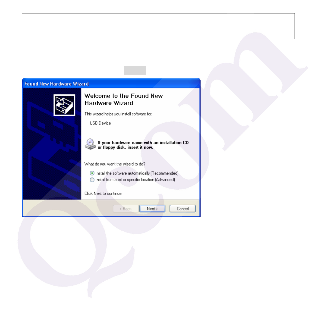
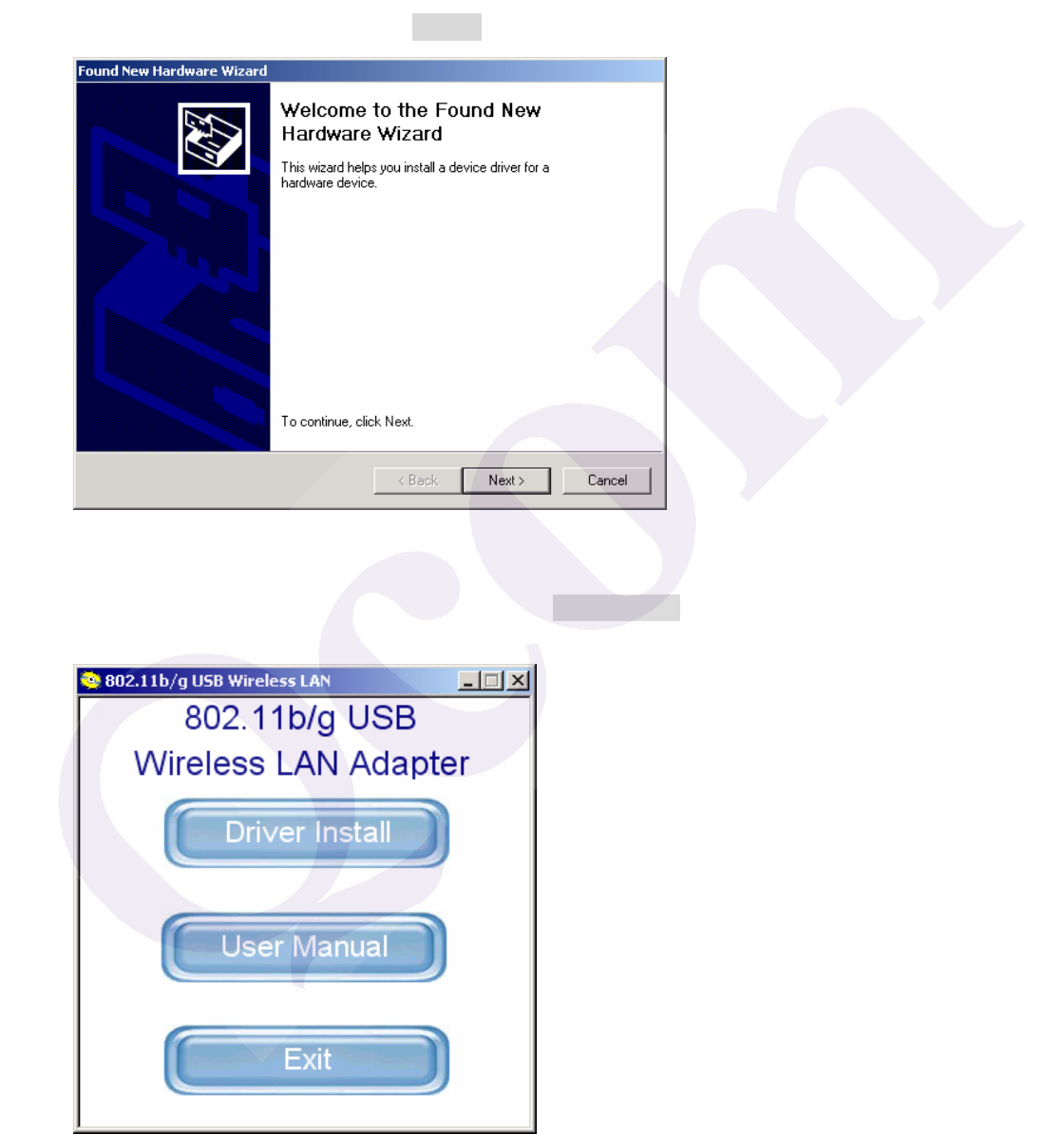
1. After you have installed the Wireless Adapter your computer will display a Found New
Hardware Wizard screen, click Cancel to continue.
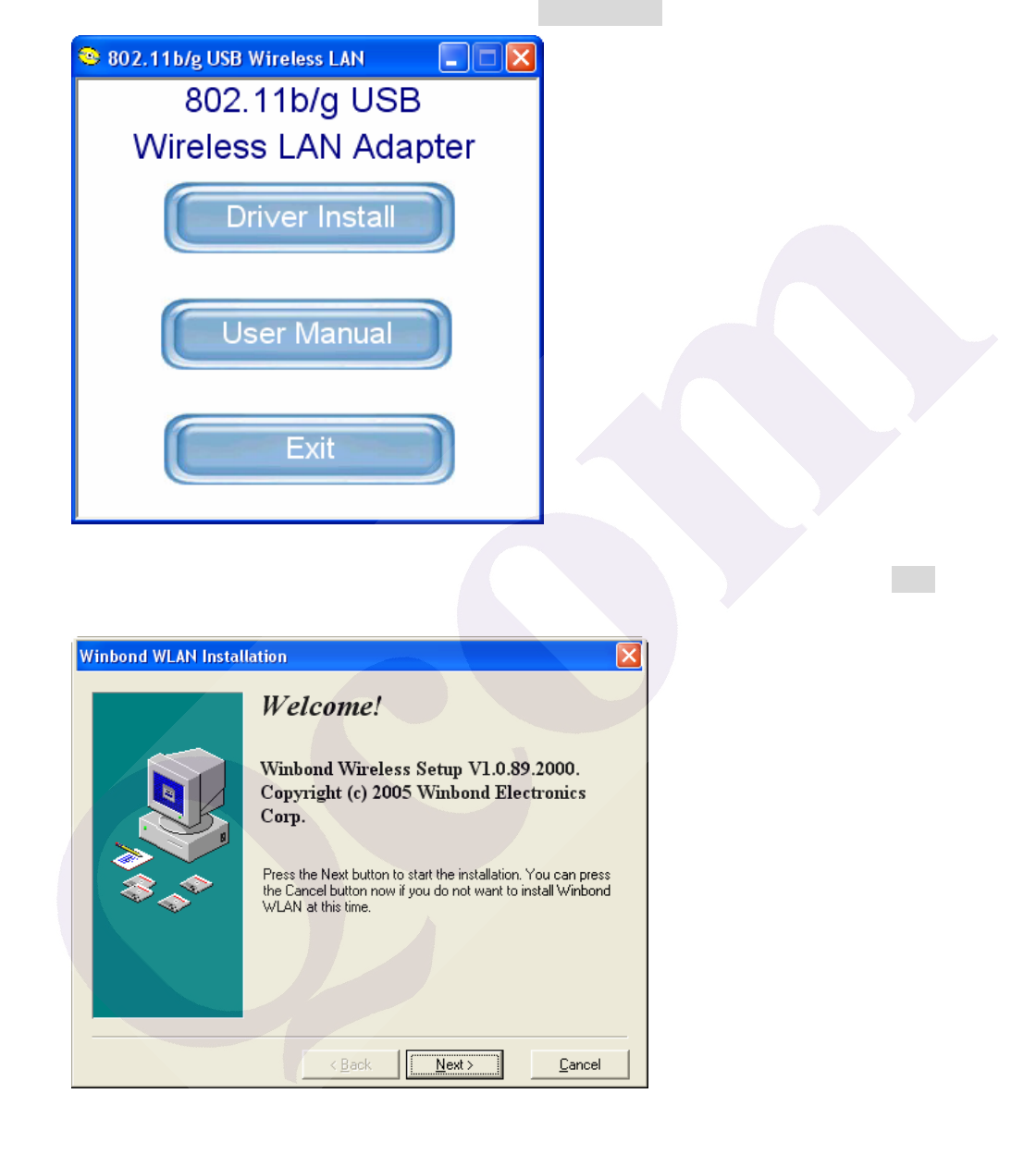
2. Insert Wireless Adapter Installation and User’s Manual CD into your CD-ROM, then the
installation will be activated automatically. Click the Driver Install icon to begin the installation.
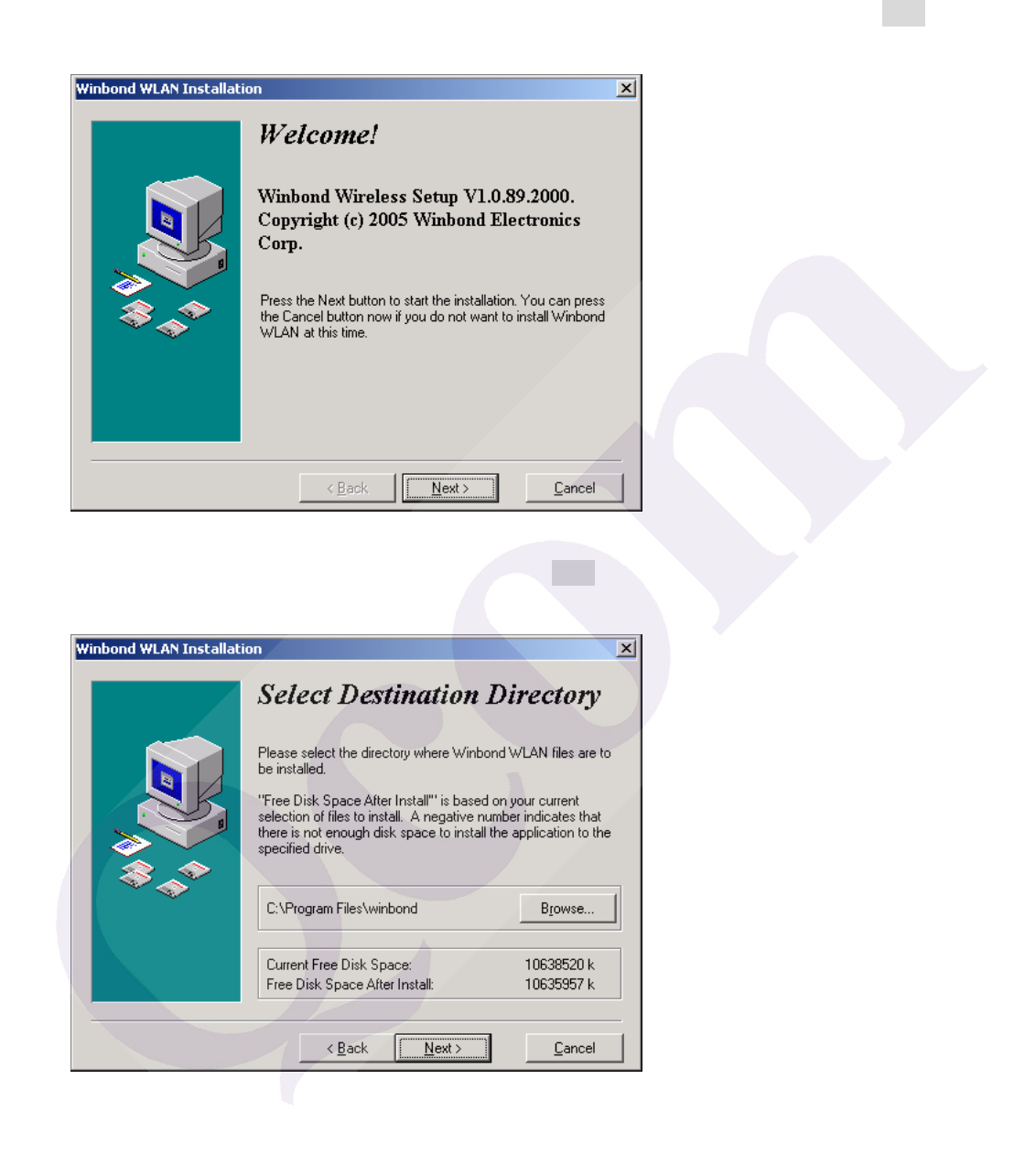
3. Winbond Wireless Setup will install the driver and utility on your system, click Next to
continue.
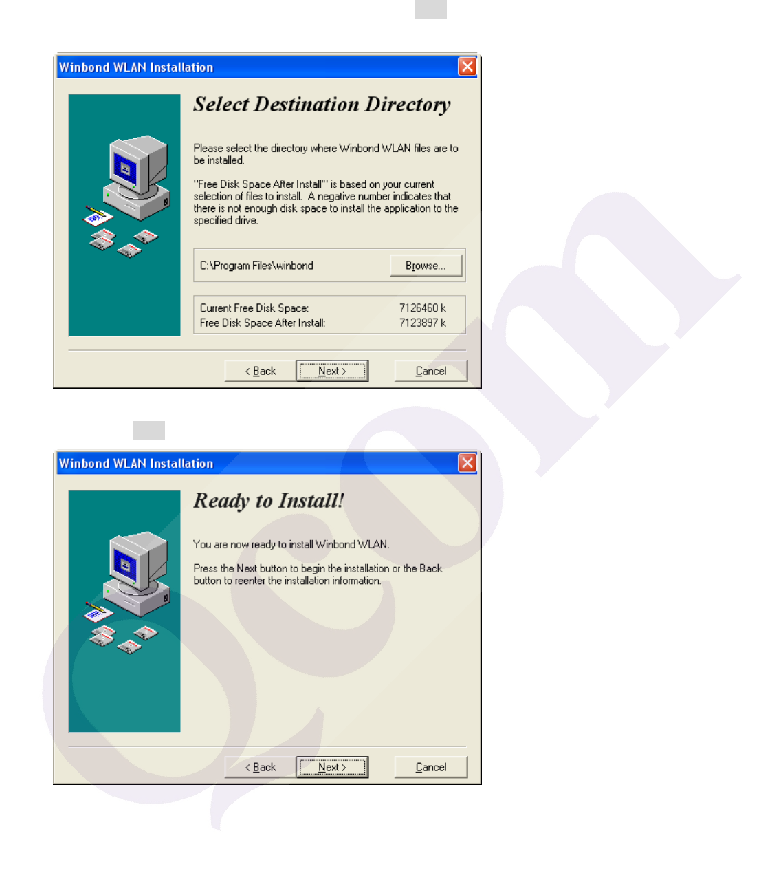
4. On the Select Destination Directory screen, click Next to accept the Destination Directory for
driver installation.
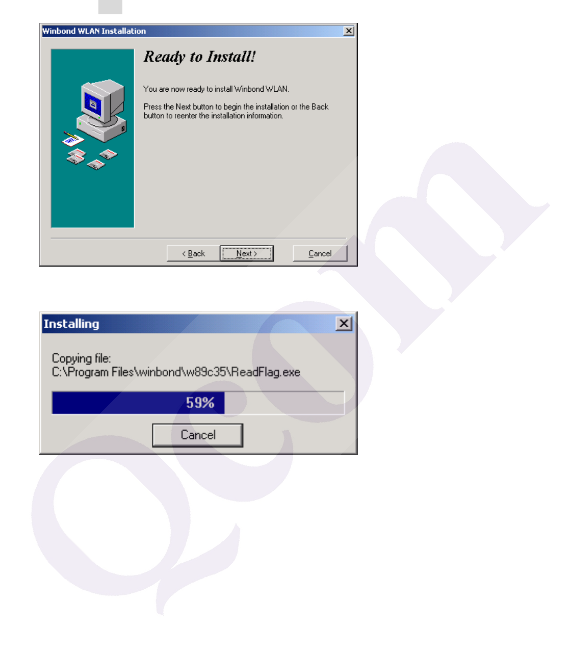
5. Press the Next button to begin the installation.
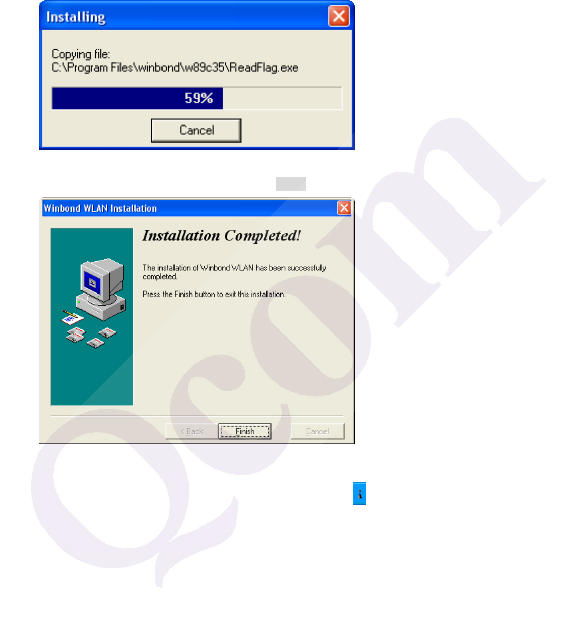
6. Wireless Adapter Driver and Utility are installing.
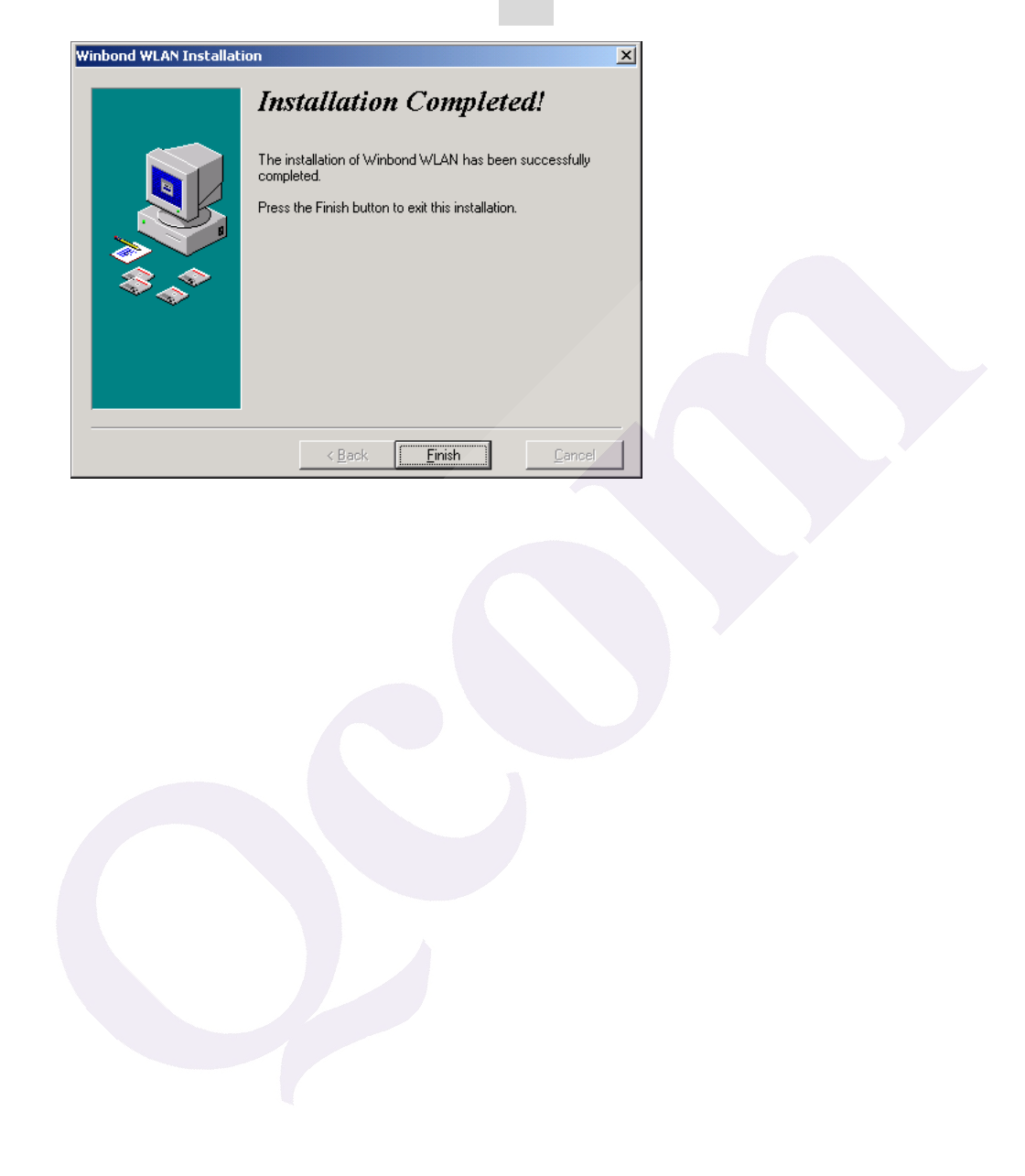
7. The installation is now complete, please click Finish.
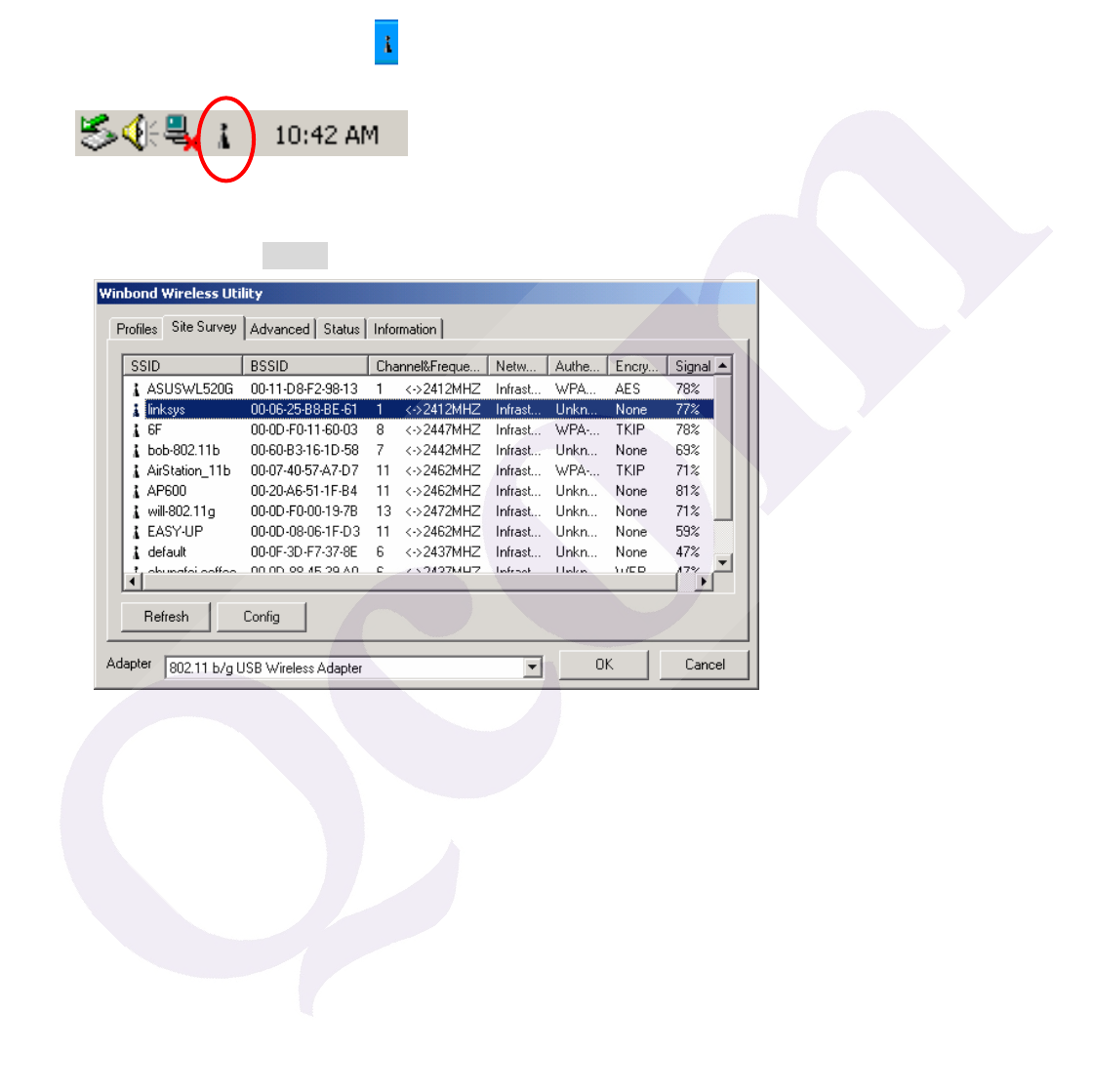
Note: When you complete the installation, the utility icon will appear on the system
tray. If not, it means that the installation failed. Please uninstall the driver and repeat
the process.
Configuring the Winbond Wireless Utility
Note: If you have installed the Windows XP Service Pack 2. You can use the Windows
Zero Configuration for Wireless Configuring. Please see the Windows XP User Guide.
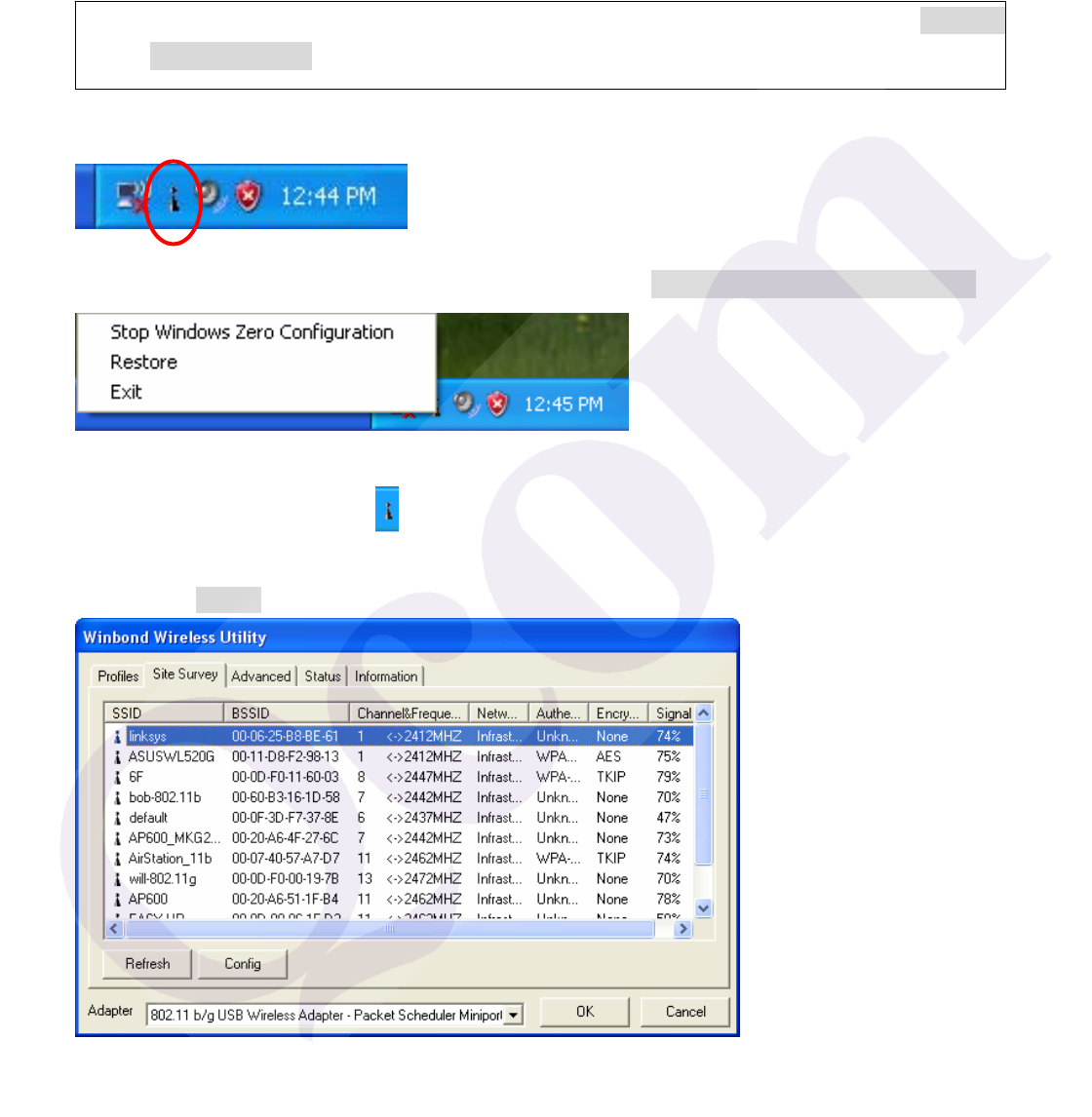
1. On the Notification Area, right-click the Winbond Utility icon.
2. Winbond Utility Selection screen will be displayed, click Stop Windows Zero Configuration.
3. Double-click the utility icon in your system tray to begin the utility configuration. Select Site
Survey Tab, all available Access Points would be listed. Click on the desired Access Point, and
click the Config button for Wireless configuring.
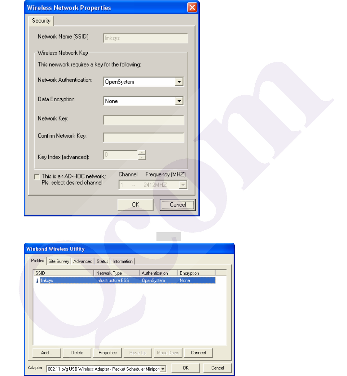
4. On the Wireless Network Properties screen, you may set Network Name (SSID), Wireless
Network Security Key or AD-HOC network.
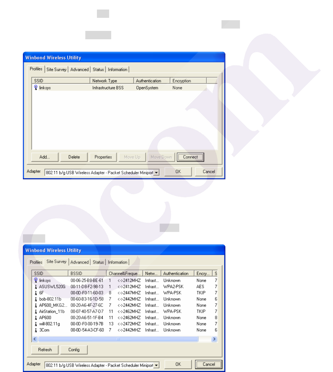
5. Click on the desired profile, and click the Connect button to take effect.
Configuration
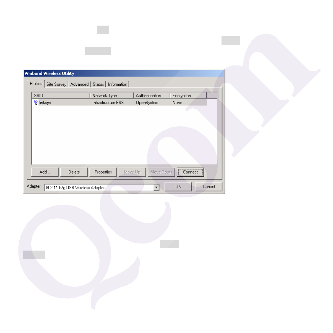
z Profile
The Profile Tab allows you to set values for all parameters by selecting a previously defined profile.
To create a profile, click Add, type a profile name and set the corresponding parameters. If one of
the profiles is no longer used, you may remove it by clicking the Delete button. After changing
parameters, click the Connect button to take effect. You can have multiple profiles and modify the
profile at any time.
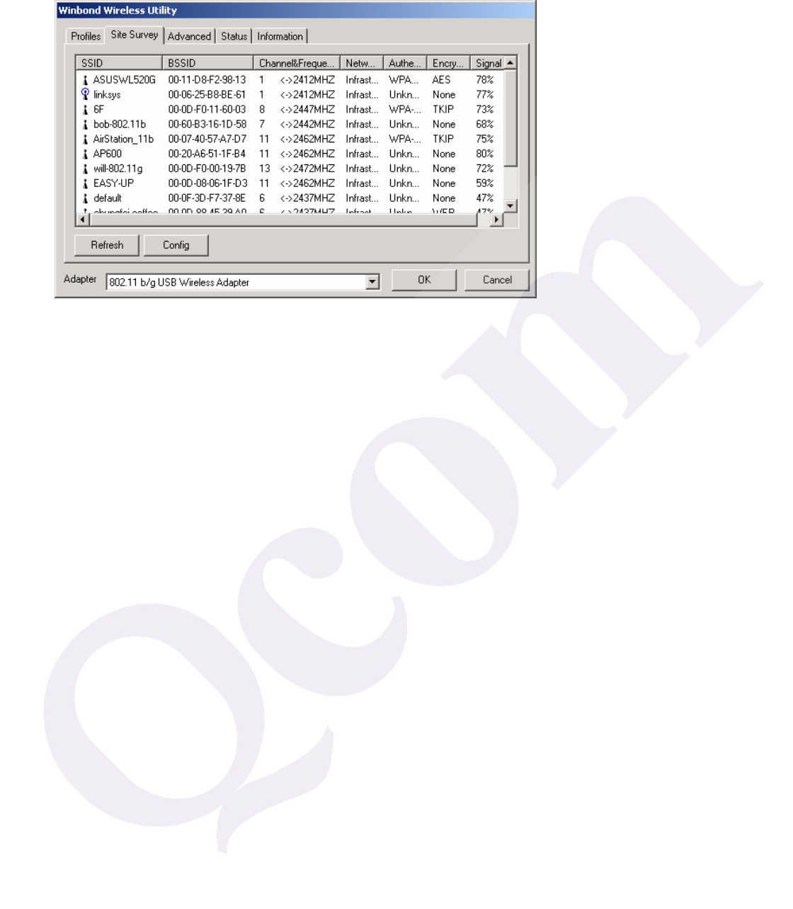
z Site Survey
Site Survey Tab lists the features of the available Access Points within range of the Wireless
Adapter's signal.
Click on the desired Access Point, and click Config for Wireless Configuration. You may click
Refresh to refresh the list.
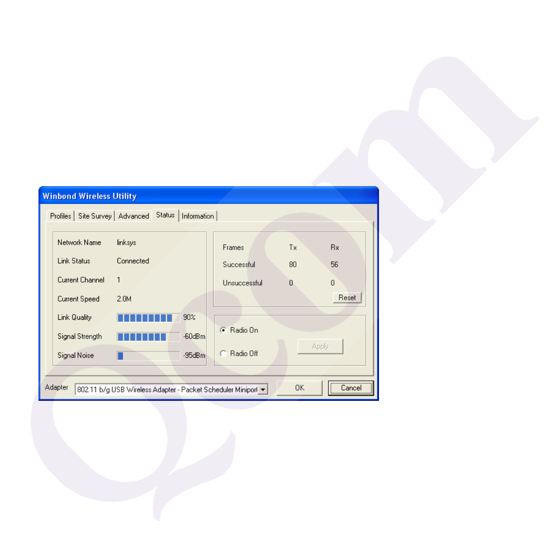
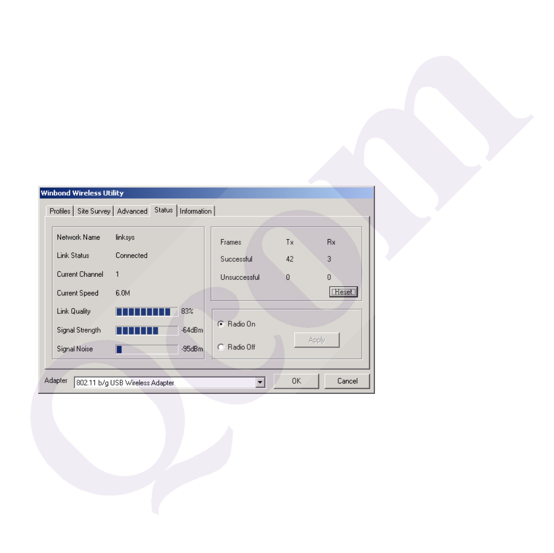
z Status
Network Name
The field shows the association status to available Access Point with SSID of the Access Point.
Link Status
Shows the whether the link is Connect or Disconnected.
Current Channel
Shows the channel on which the connection is made.
Current Speed
Shows the highest transmit rate of the current association.
Link Quality / Signal Strength
The Link Quality and Signal Strength bar graph is only active when the node is in Infrastructure
Mode. The bar graph displays the quality and strength of the link between the node and its Access
Point.
Singnal Noise
This displays the noise level of the link between the node and its Access Point.
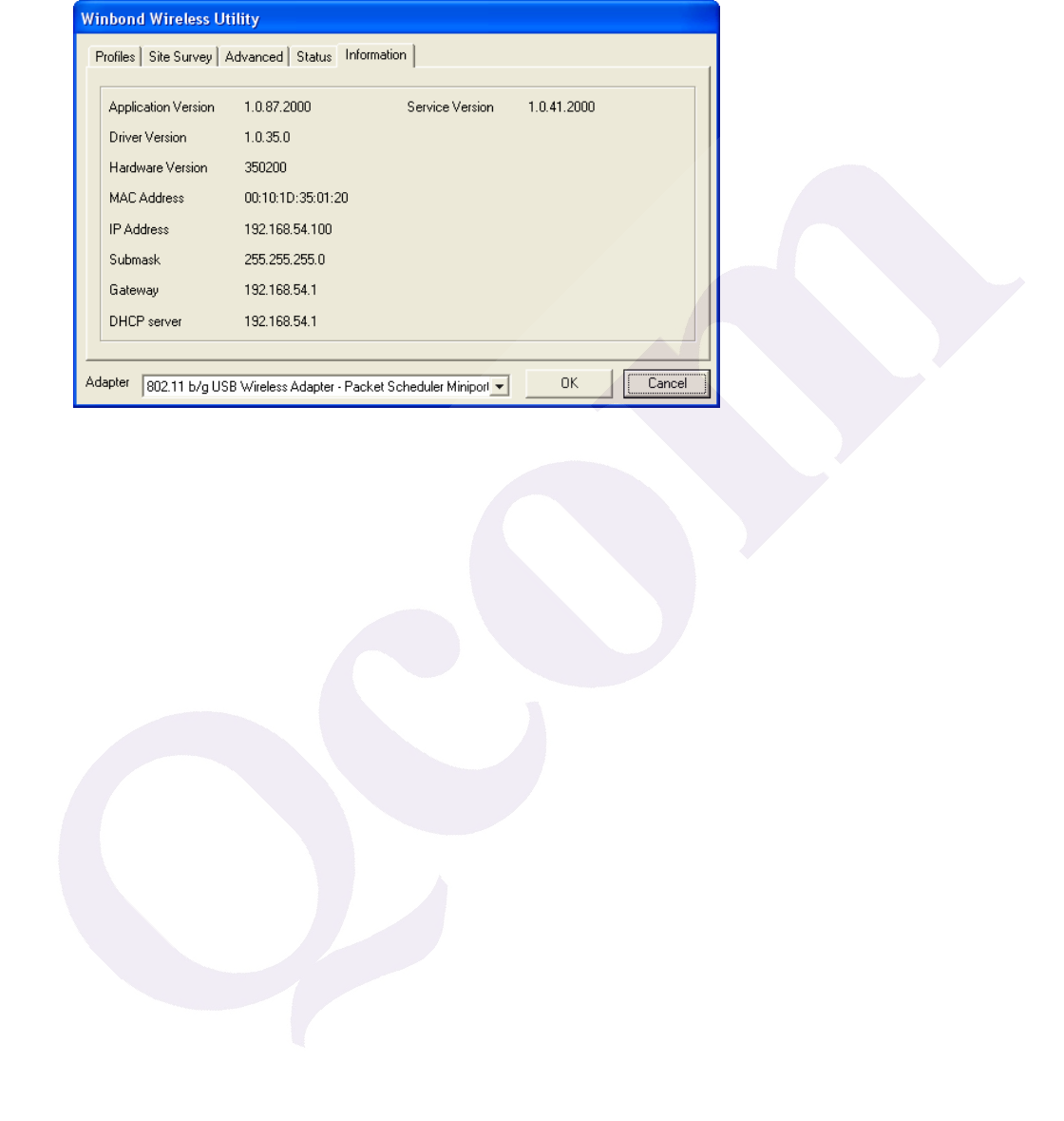
z Information
About Tab shows the product version including the detail of Configuration Utility, Driver, and NIC
MAC Address.
Uninstalling the Wireless Adapter Driver and Utility
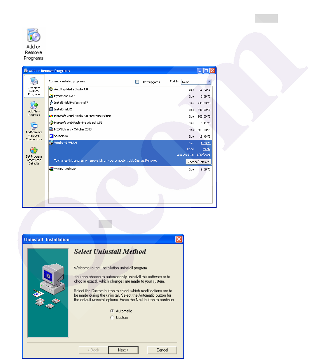
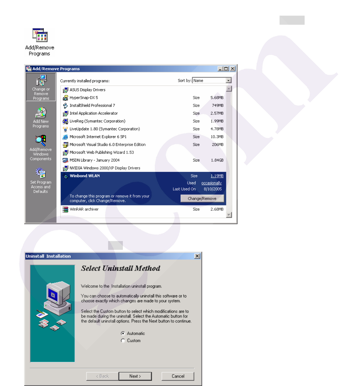
1. For uninstalling the Wireless Adapter, please go to:Start->Settings->Control Panel->Add or
Remove Programs->Winbond WLAN under Windows environment. Then click Remove.
2. On the next screen, click Next button to accept automatically uninstall for Wireless LAN Driver.
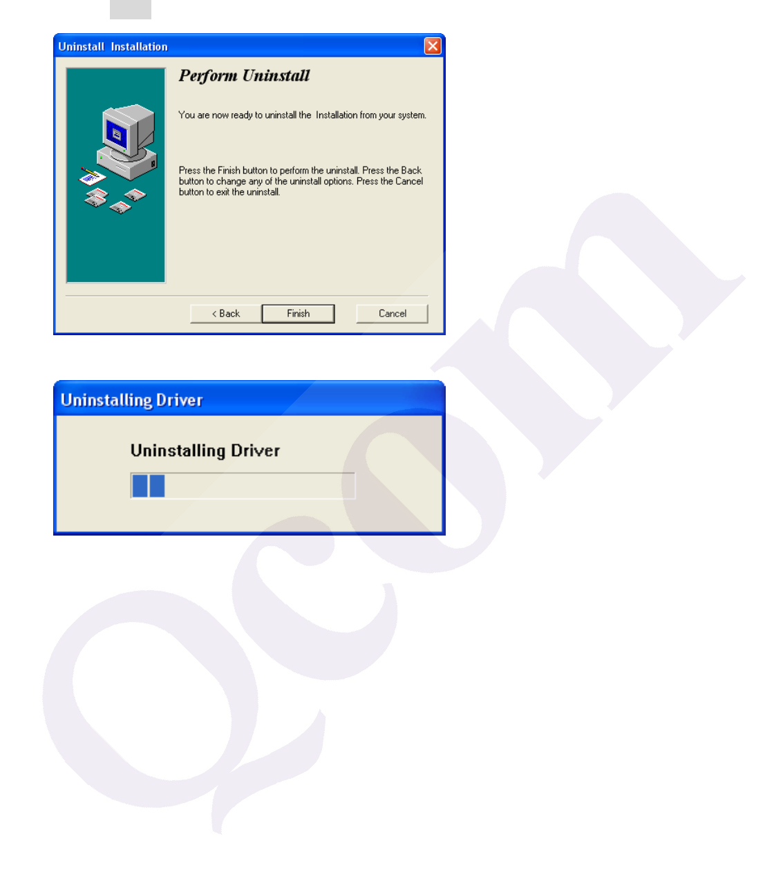
3. Click Finish button.
4. The USB Wireless Adapter can now be safely removed from the system when the un-installation
is done.
Windows 2000:
1. After you have installed the Wireless Adapter your computer will display a Found New
Hardware Wizard screen, click Cancel to continue.
2. Insert Wireless Adapter Installation and User’s Manual CD into your CD-ROM; then the
installation will be activated automatically. Click the Driver Install icon to begin the installation.
3. Winbond Wireless Setup will install the driver and utility on your system, click Next to
continue.
4. On the Select Destination Directory screen, click Next to accept the Destination Directory for
driver installation..
5. Press the Next button to begin the installation.
6. Wireless Adapter Driver and Utility are installing.
7. The installation is now complete, please click Finish.
Configuring the Winbond Wireless Utility
1. Double-click the utility icon in your system tray to begin the utility configuration..
2. Select Site Survey Tab, all available Access Points would be listed. Click on the desired Access
Point, and click Config button for Wireless configuring.
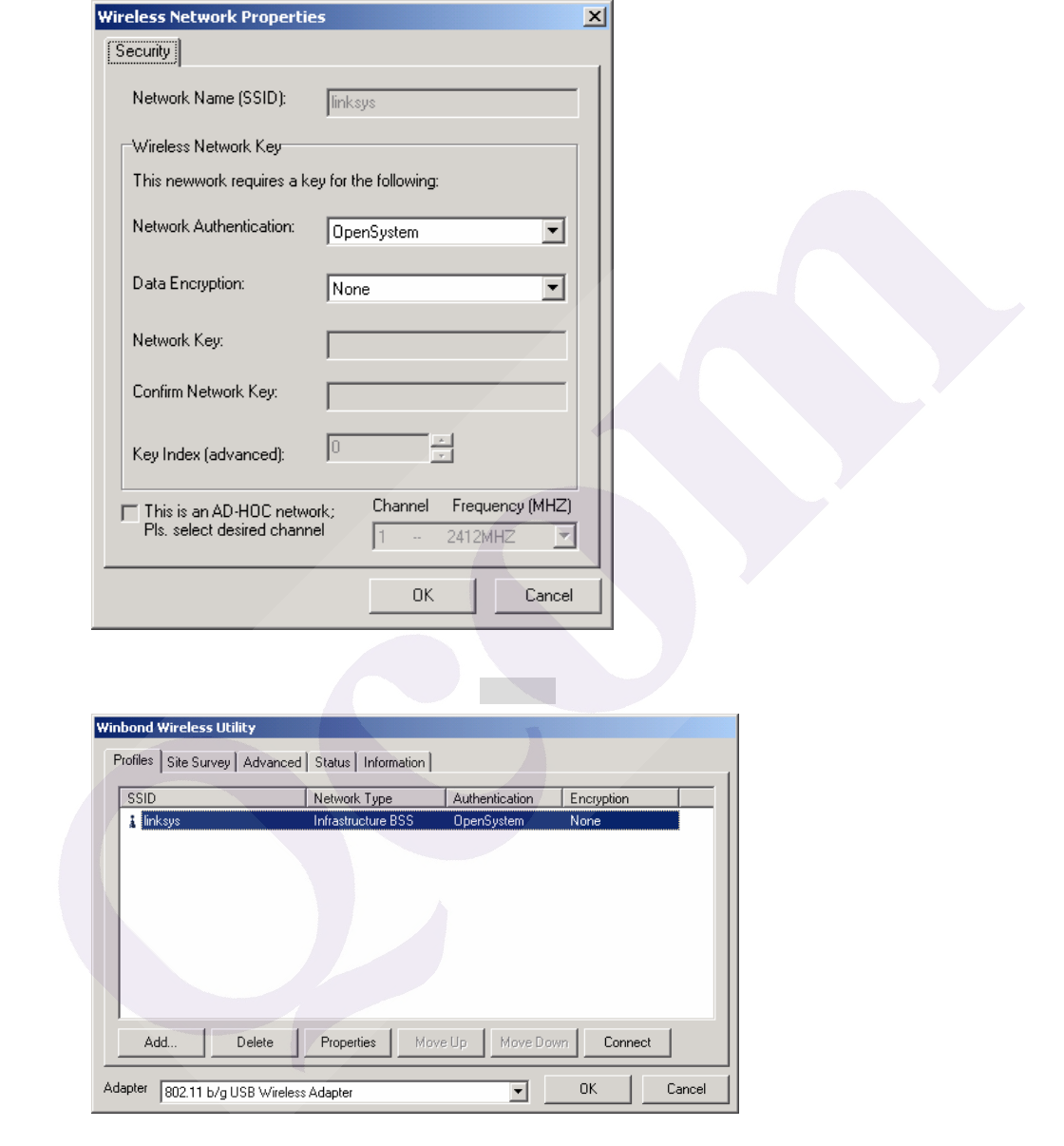
3. On the Wireless Network Properties screen, you may set Network Name (SSID), Wireless
Network Security Key or AD-HOC network.
4. Click on the desired profile, and click the Connect button to take effect.
Configuration
z Profile
The Profile Tab allows you to set values for all parameters by selecting a previously defined profile.
To create a profile, click Add, type a profile name and set the corresponding parameters. If one of
the profiles is no longer used, you may remove it by clicking the Delete button. After changing
parameters, click the Connect button to take effect. You can have multiple profiles and modify the
profile at any time.
z Site Survey
Site Survey Tab lists the features of the available Access Points within range of the Wireless
Adapter's signal.
Click on the desired Access Point, and click Config for Wireless Configuration. You may click
Refresh to refresh the list.
z Status
Network Name
The field shows the association status to available Access Point with SSID of the Access Point.
Link Status
Shows the whether the link is Connect or Disconnected.
Current Channel
Shows the channel on which the connection is made.
Current Speed
Shows the highest transmit rate of the current association.
Link Quality / Signal Strength
The Link Quality and Signal Strength bar graph is only active when the node
is in Infrastructure Mode. The bar graph displays the quality and strength of
the link between the node and its Access Point.
Singnal Noise
This displays the noise level of the link between the node and its Access Point.
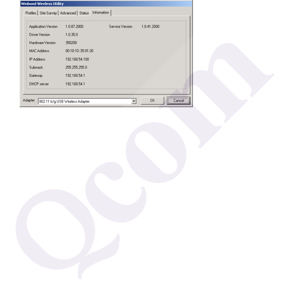
Information
About Tab shows the product version including the detail of Configuration Utility, Driver, and NIC
MAC Address.
Uninstalling the Wireless Adapter Driver and Utility
1. For uninstalling the Wireless Adapter, please go to:Start->Settings->Control Panel->Add or
Remove Programs->Winbond WLAN under Windows environment. Then click Remove.
2. On the next screen, click Next button to accept automatically uninstall for Wireless LAN Driver.
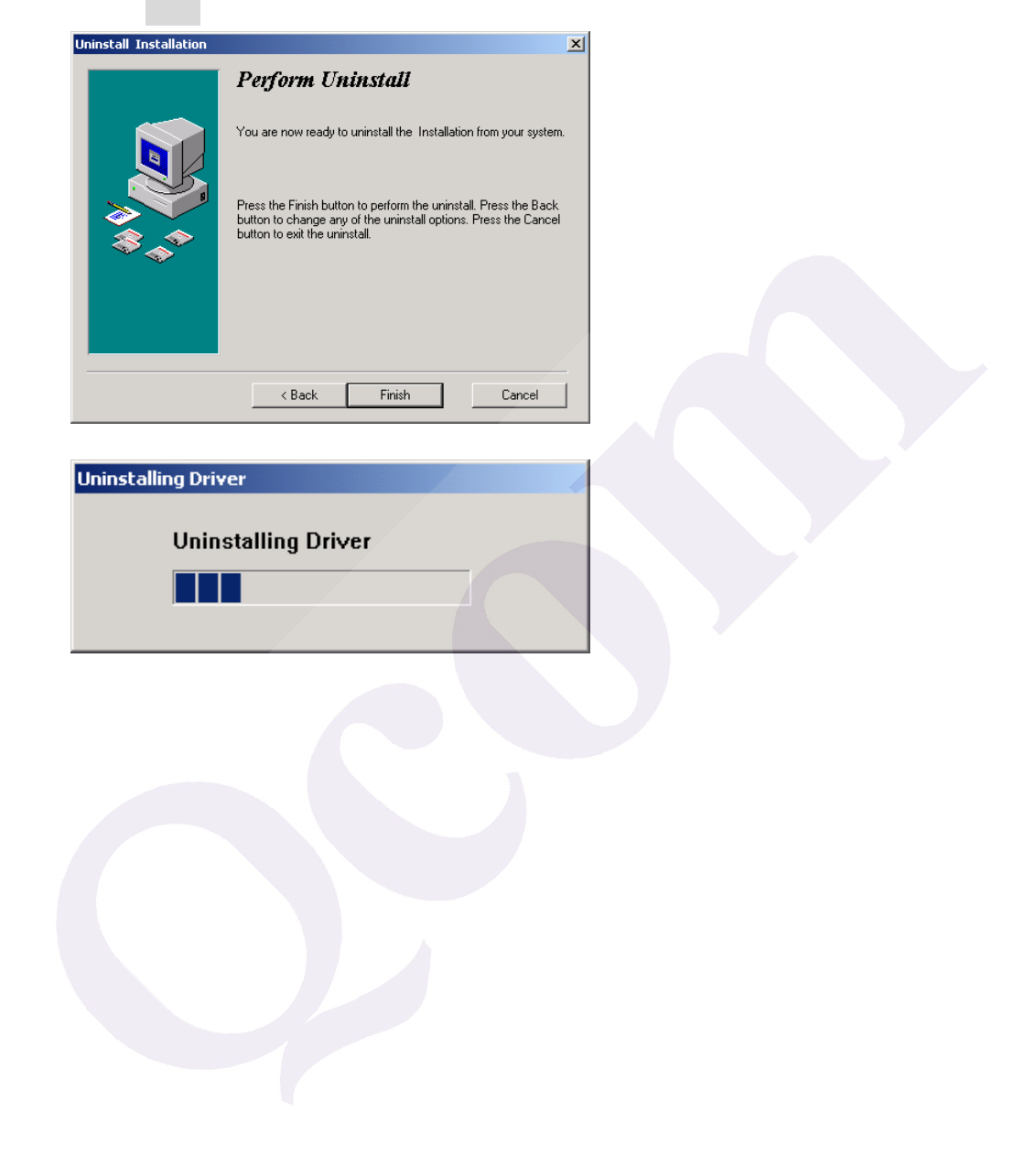
3. Click Finish button.
4. The USB Wireless Adapter can now be safely removed from the system when the un-installation
is done.

Trouble shooting
PING
This section discusses possible solutions using ping command to find your problem if you can’t connect to the
network.
1. Check if you have a valid IP address
2. Test if your TCP/IP works. Under MS-DOS (command prompt), type “ping localhost”. If you didn’t
receive a reply, then you need to re-install your TCP/IP. Proceed to next step if you have received
replies.
3. Using the same procedure, try to ping your Wireless Adapter’s IP. If the Ping command fails, check the
following:
• Your WLAN is connected
• Check that your driver is correctly installed.

Checking Valid IP Addresses
There are restrictions on which IP and addresses you can and cannot use. Some IP addresses are reserved
for testing, multicasting and some IP are restricted by your ISP.
Following IP addresses cannot be used:
¾ 127.x.x.x – this is a loop back address, used for testing
¾ 0.0.0.0 – this IP address represent the host address
¾ 255.255.255.255 – this is local broadcast address
¾ First portion of IP cannot exceed 224, that is, IP addresses which is in the range of 224~239.x.x.x
is not valid. This range of IP is for multicasting. IP range from 240~255.x.x.x are reserved IP
addresses and cannot be used.
¾ 0 or 255 in host ID portion of your IP are not valid. This represent local host or broadcast address
for your class of IP
IP has five classes, namely class A, B, C, D and E. For each class, the host ID portion in the IP field is
different for each of the classes. Figure below illustrate this.
Class A: 1 ~ 127 . Host ID
Class B: 128 ~ 191 . X . Host ID
Class C: 192 ~ 223 . X . X . Host ID
Class D: 224 ~ 239 . Used for Multicasting (no Host ID)
Class E: 240 ~ 255 . Reserved IP address
Host ID cannot be all 0’s or all 255’s.
Note: X denote don’t cares in the above example.

Federal Communication Commission Interference Statement
This equipment has been tested and found to comply with the limits for
a Class B digital device, pursuant to Part 15 of the FCC Rules. These
limits are designed to provide reasonable protection against harmful
interference in a residential installation. This equipment generates,
uses and can radiate radio frequency energy and, if not installed and
used in accordance with the instructions, may cause harmful
interference to radio communications. However, there is no guarantee
that interference will not occur in a particular installation. If this
equipment does cause harmful interference to radio or television
reception, which can be determined by turning the equipment off and
on, the user is encouraged to try to correct the interference by one of
the following measures:
- Reorient or relocate the receiving antenna.
- Increase the separation between the equipment and receiver.
- Connect the equipment into an outlet on a circuit different from that
to which the receiver is connected.
- Consult the dealer or an experienced radio/TV technician for help.
This device complies with Part 15 of the FCC Rules. Operation is
subject to the following two conditions: (1) This device may not cause
harmful interference, and (2) this device must accept any interference
received, including interference that may cause undesired operation.
FCC Caution: Any changes or modifications not expressly approved by
the party responsible for compliance could void the user's authority to
operate this equipment.
IMPORTANT NOTE:
FCC Radiation Exposure Statement:
This equipment complies with FCC radiation exposure limits set forth
for an uncontrolled environment. End users must follow the specific
operating instructions for satisfying RF exposure compliance.
This transmitter must not be co-located or operating in conjunction with
any other antenna or transmitter.
"Qcom declare that Q802UWG is limited in CH1~CH11 by specified
firmware controlled in USA."

INFORMATION TO USER:
The users manual or instruction manual for an intentional or
unintentional radiator shall caution the user that changes or
modifications not expressly approved by the party responsible for
compliance could void the user’s authority to operate the equipment.