Qcom Technology Q802XKN 802.11 b/g/n Wireless PCI Express Mini Card User Manual Q802XKN Manual rev
Qcom Technology Inc. 802.11 b/g/n Wireless PCI Express Mini Card Q802XKN Manual rev
UserManual.wiki
>
Qcom Technology
>
Q802XKN User Manual
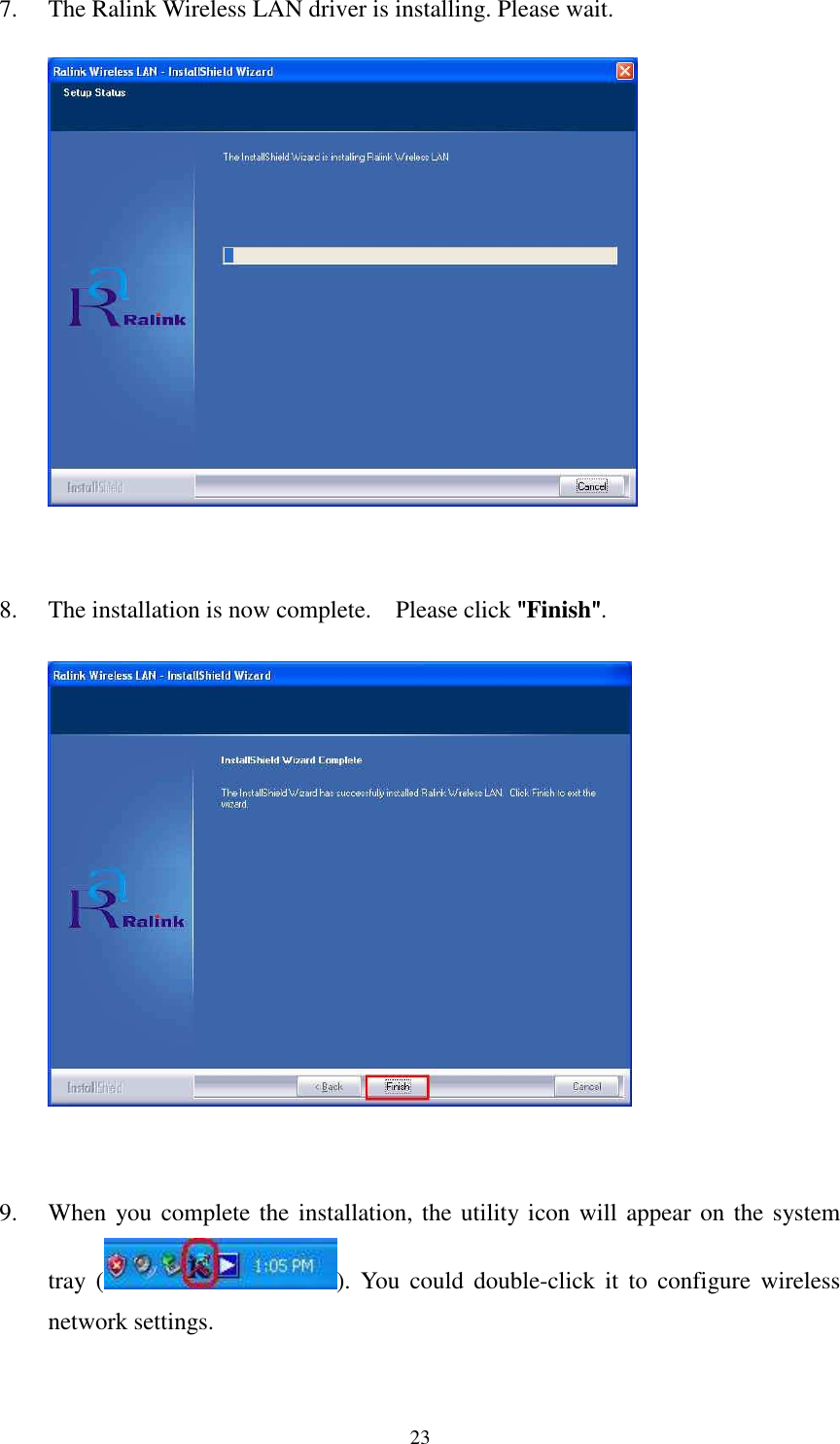
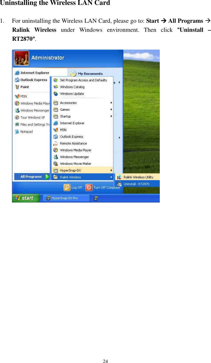
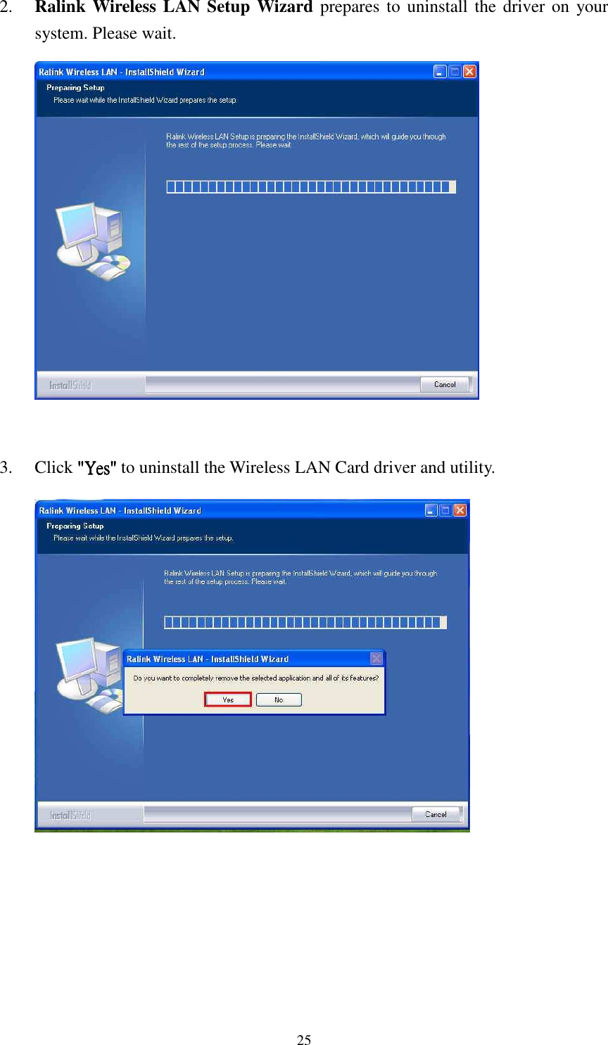
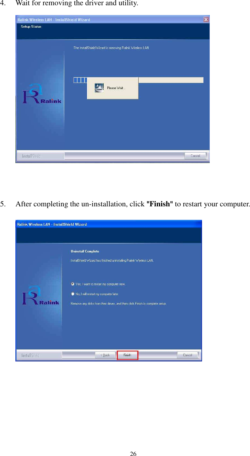
Manual
Navigation menu
Upload a User Manual
Namespaces
Wiki Guide
HTML
PDF
Info
Views
User Manual
Discussion / Help
Navigation