Qingdao Hisense Intelligent Commercial System VC220 Customer Display User Manual VC220 Manual
Qingdao Hisense Intelligent Commercial System Co., Ltd. Customer Display VC220 Manual
User Manual
VC220 Manual
1 Customer Display Components...................................................................................... 2
2 Customer Display Installation......................................................................................... 3
3Customer Display Set Discription.................................................................................... 3
3.1 Install customer display setup software................................................................ 3
3.2 Use customer display setup software .................................................................. 3
4Customer Display Test .................................................................................................... 6
4.1 Test software installation...................................................................................... 6
4.2 Use the testing software....................................................................................... 6
5.Customer Display Specifications.................................................................................... 8
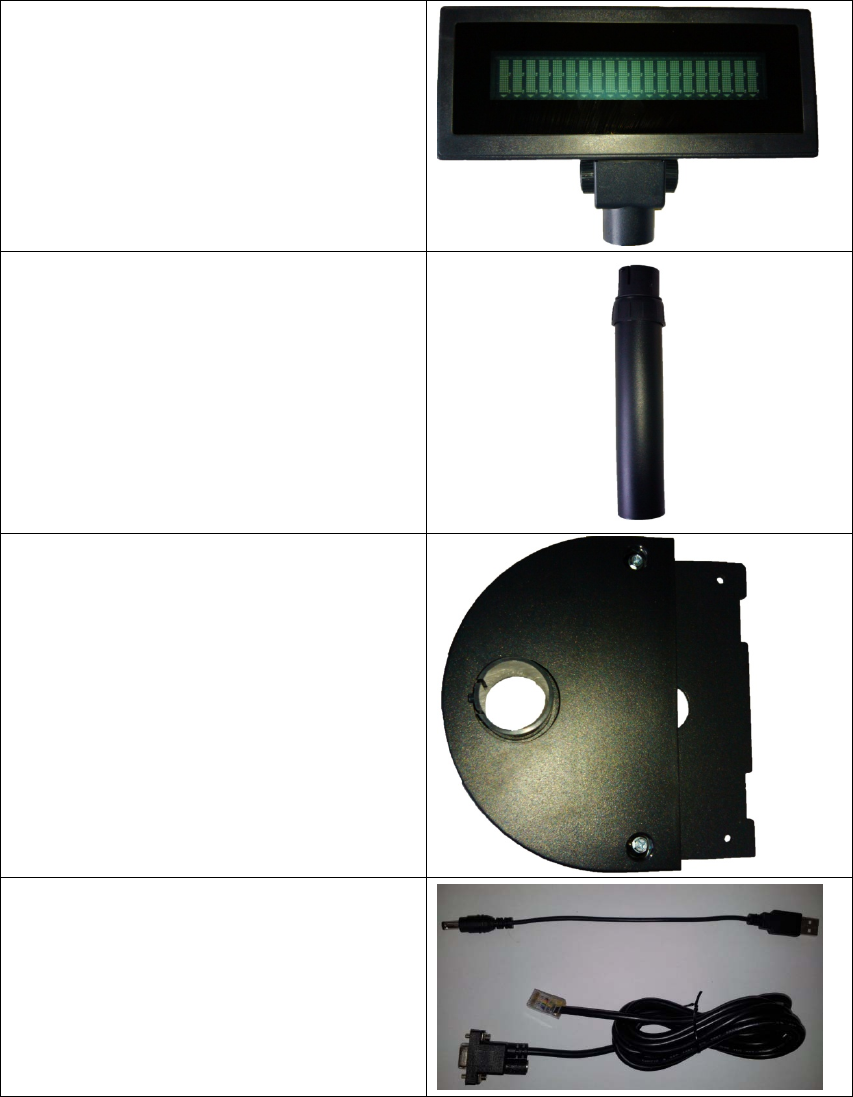
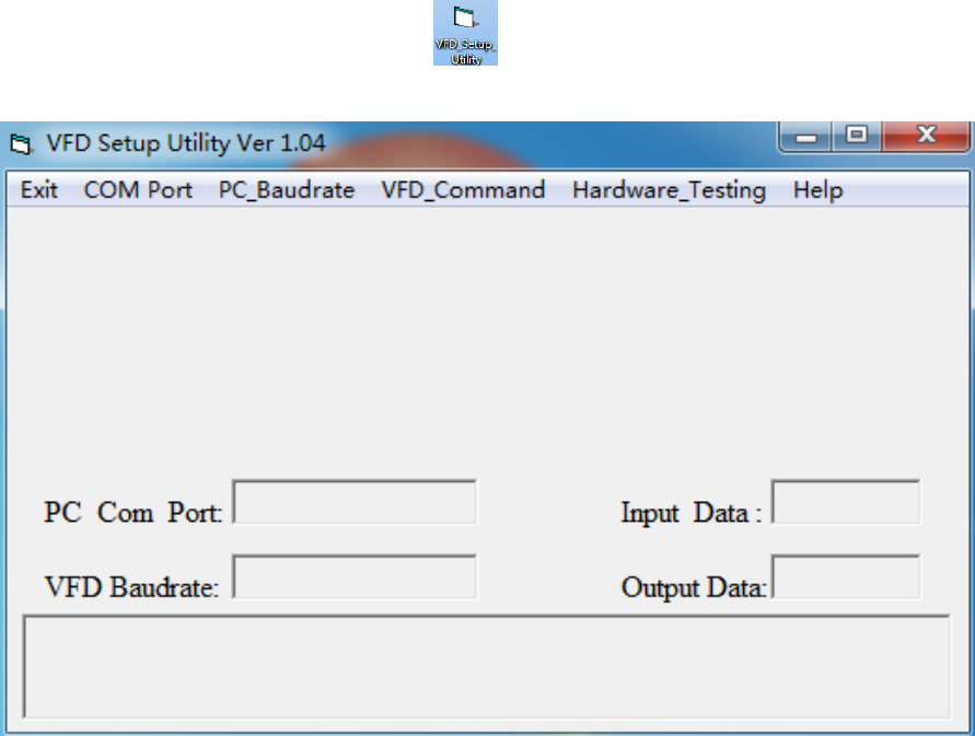
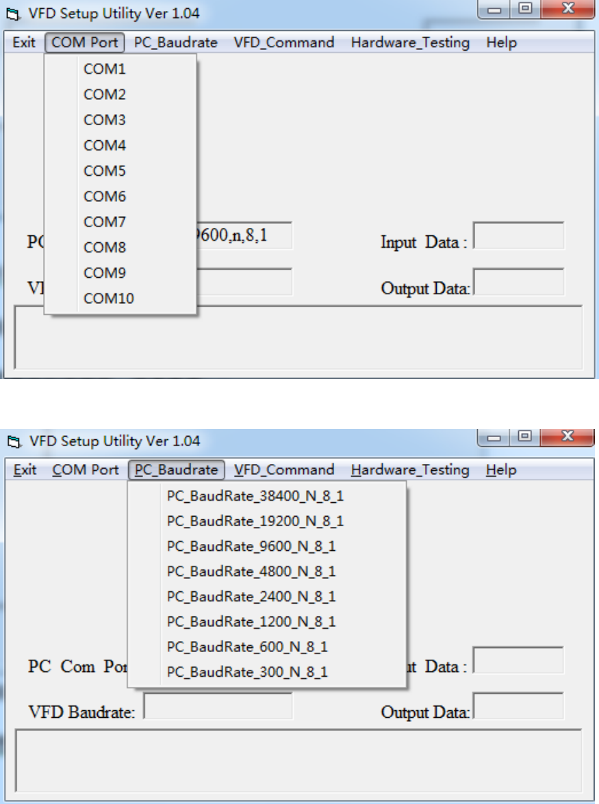
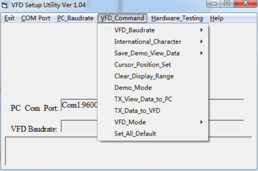
1 Customer Display Components
1. VFD Disnplay
2.Customer Display Pole
3. Customer Display Base
4. Customer Display Cable
2 Customer Display Installation
① Connect customer display components to bottom plate expansion
board, connect signal cable to COM3;plug one side of power supply into
motherboard USB interface, plug the other side into circular power port of
the customer display signal cable.
② Push forward the whole component into the host, which having location clip
on the left and right side;
③ Fix screws with screw driver from top to bottom to prevent them falling off.
3Customer Display Set Discription
3.1 Install customer display setup software
Double click setup software, accept all the default settings.
3.2 Use customer display setup software
①double click VFD_Setup_Utilityicon on the desktop.
②open up the following interface
“COM Port” menu sets which COM port the customer display will connect to.
“PC_Baudrate” menu sets computer Baud rate.
“VFD_Command” menu sets customer display’s Baud rate, language and so
on.
4Customer Display Test
4.1 Test software installation
Double click setup software, accept all the default settings.
4.2 Use the testing software
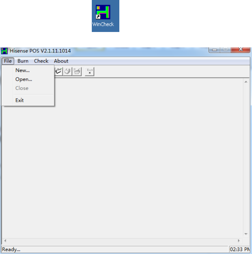
①double click Wincheck icon on the desktop.
②click “file”-“new” on the interface.
③Printer chooses ‘NONE’ , LineDisplay chooses ‘VC220’ , LineDisplay port
chooses the corresponding port that customer display connects to .
Mainboard chooses ‘D525’,COM CashDrawer chooses “NONE”, and other
options accept the default settings, then click “OK” button。
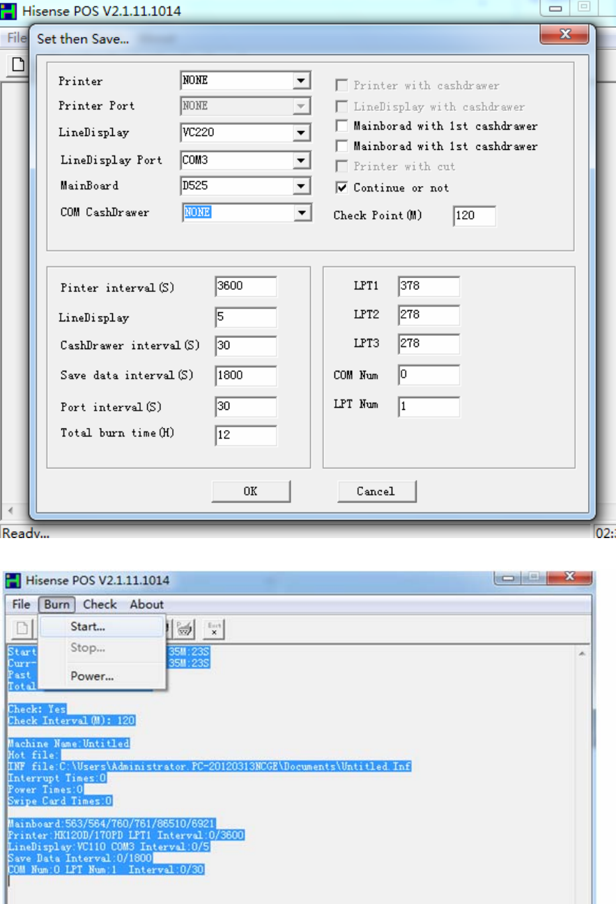
④click “save” button, then click “Burn”-“Start”.

5.Customer Display Specifications
Model VC220
Display mode VFD
Character color Green
Digital format 5*7 point Matrix
Character size 5.5*10.5 mm
Character 7.4*15.5 mm
Display area(mm) 146.1*29
Power supply +5V~+24V
Interface RS-232
Baud rate 9600
Size (W×D×H) 200mm×25mm×65mm
Color Dark Grey
Stereoscopic height adjustable Yes
Mean time to failure 20000 hr
Power 5W
Working temperature 0 ℃ - +75℃
Storage temperature -40 ℃ - +85℃
Working humidity 30- 85%
Storage humidity 30- 90%

Changes or modifications not expressly approved by the party responsible
for compliance could void the user's authority to operate the equipment。
NOTE: This equipment has been tested and found to comply with the
limits for a Class B digital device, pursuant to Part 15 of the FCC Rules.
These limits are designed to provide reasonable protection against
harmful interference in a residential installation. This equipment
generates, uses and can radiate radio frequency energy and, if not
installed and used in accordance with the instructions, may cause harmful
interference to radio communications. However, there is no guarantee
that interference will not occur in a particular installation. If this equipment
does cause harmful interference to radio or television reception, which
can be determined by turning the equipment off and on, the user is
encouraged to try to correct the interference by one or more of the
following measures:
-- Reorient or relocate the receiving antenna.
-- Increase the separation between the equipment and receiver.
-- Connect the equipment into an outlet on a circuit different
from that to which the receiver is connected.
-- Consult the dealer or an experienced radio/TV technician for
help.
FCC ID: GQK-VC220
This device complies with Part 15 of the FCC Rules. Operation is
subject to the following two conditions: (1) this device may not
cause harmful interference, and (2) this device must accept any
interference received, including interference that may cause
undesired operation.