Qisda T3300 Diagnostic Ultrasound System User Manual Diagnostic Ultrasound System Victoria UM en
Qisda Corporation Diagnostic Ultrasound System Diagnostic Ultrasound System Victoria UM en
UserManual.wiki
>
Qisda
>
T3300 User Manual
Users Manual
Navigation menu
Upload a User Manual
Namespaces
Wiki Guide
HTML
PDF
Info
Views
User Manual
Discussion / Help
Navigation
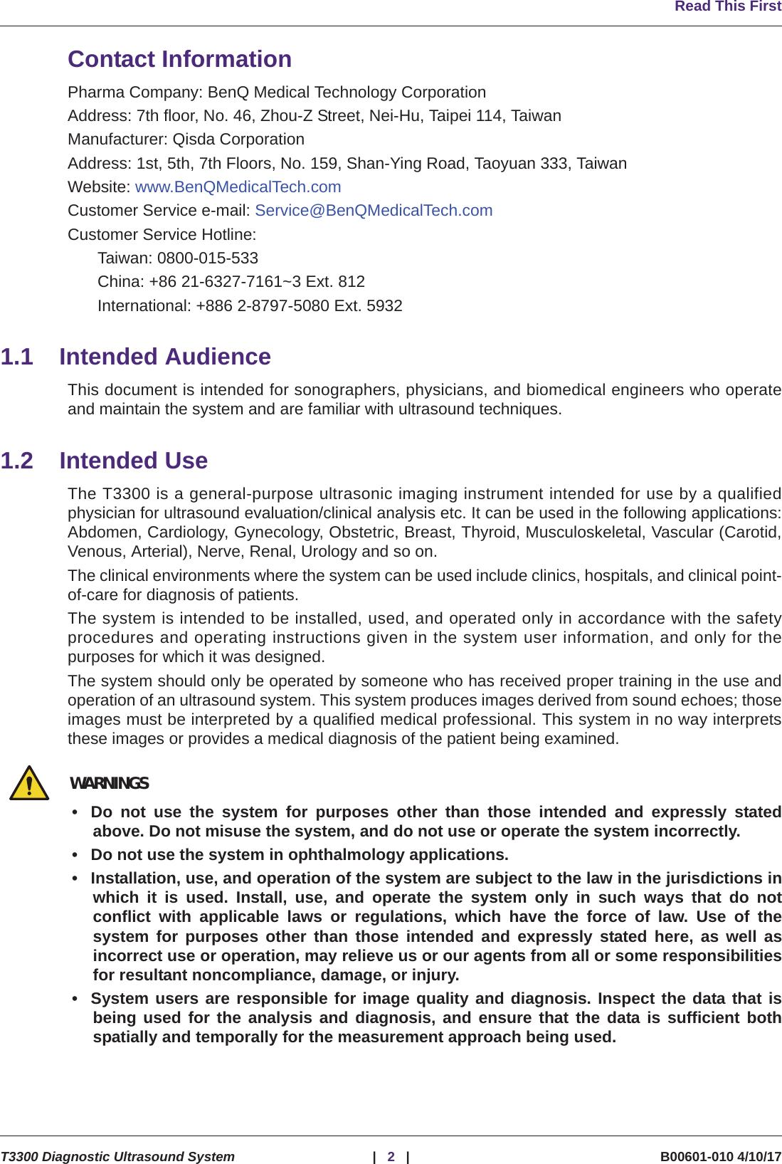
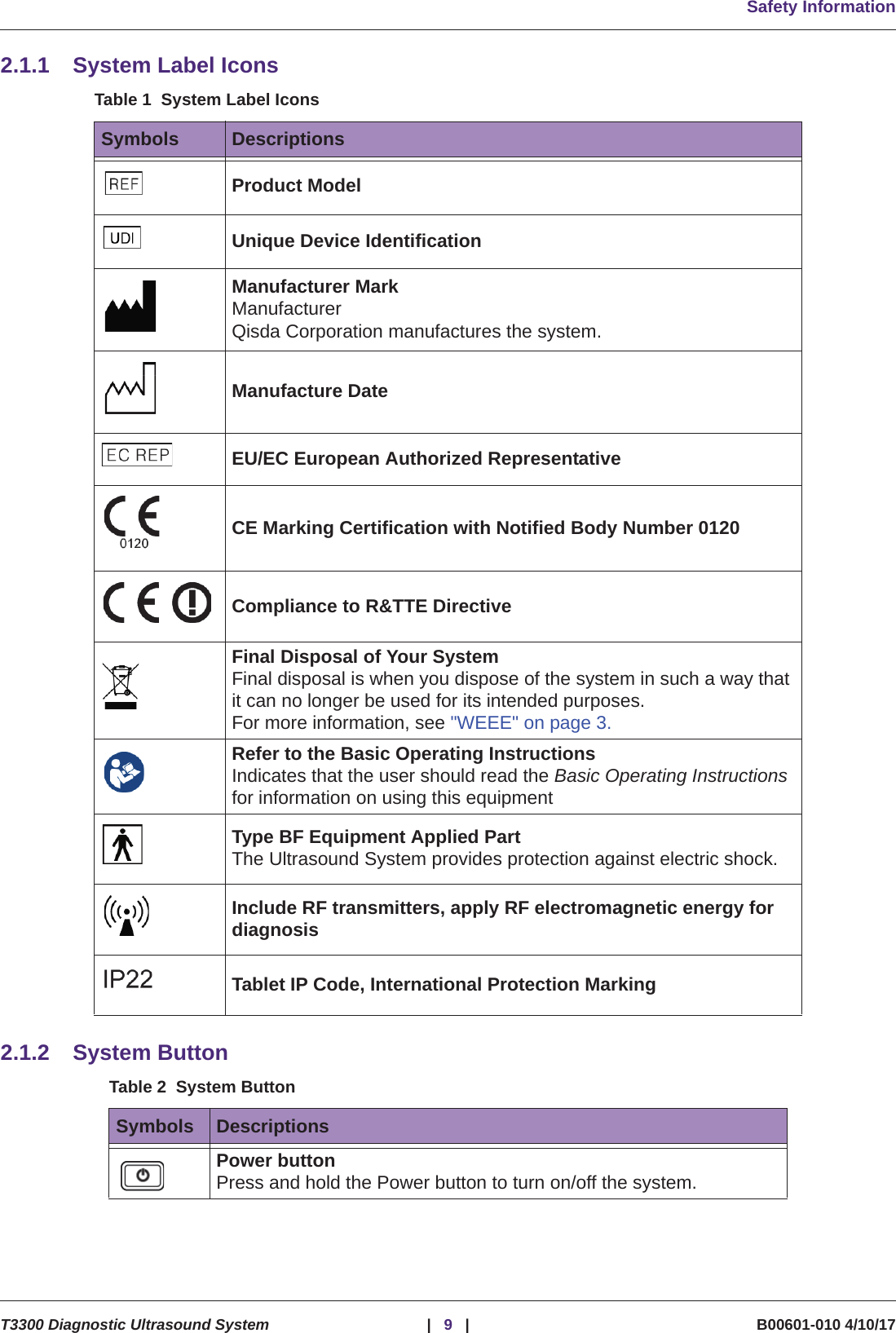
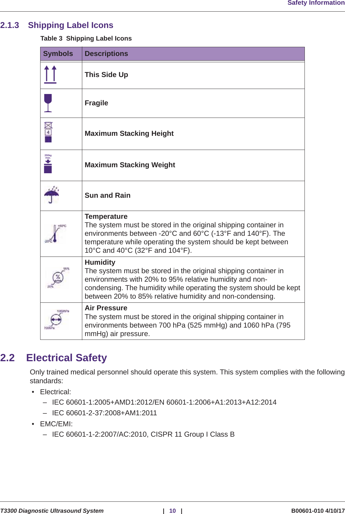
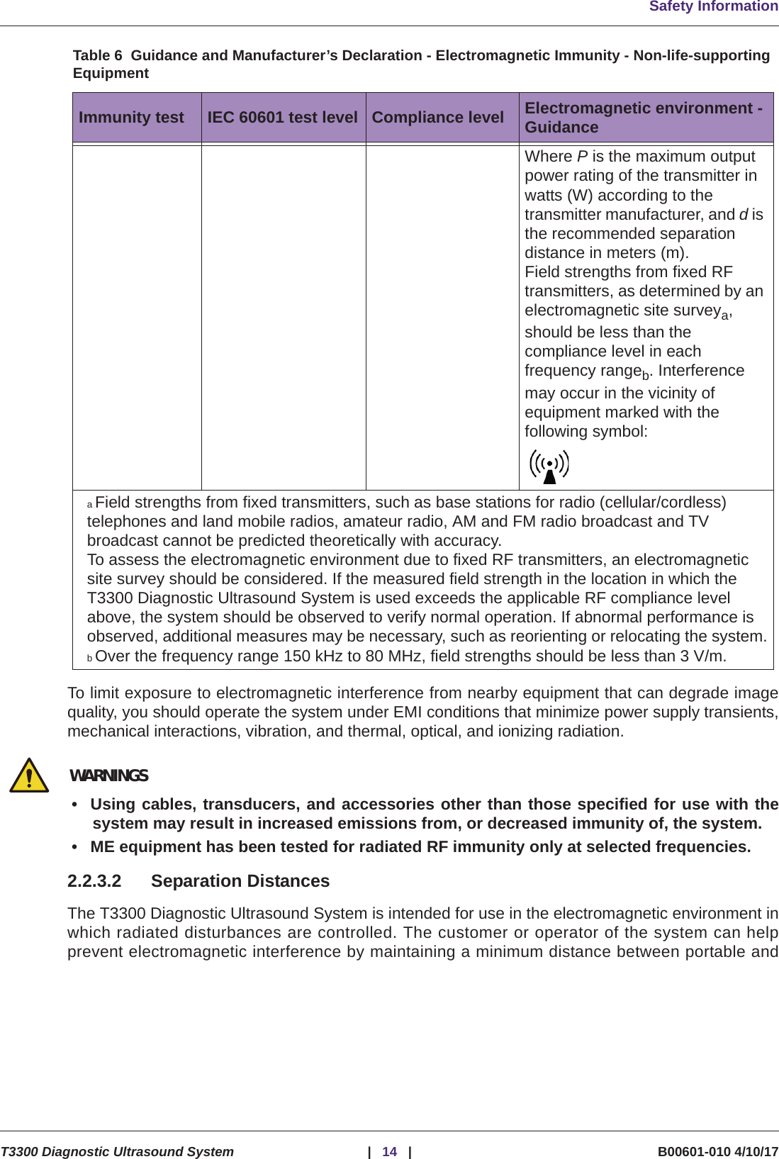
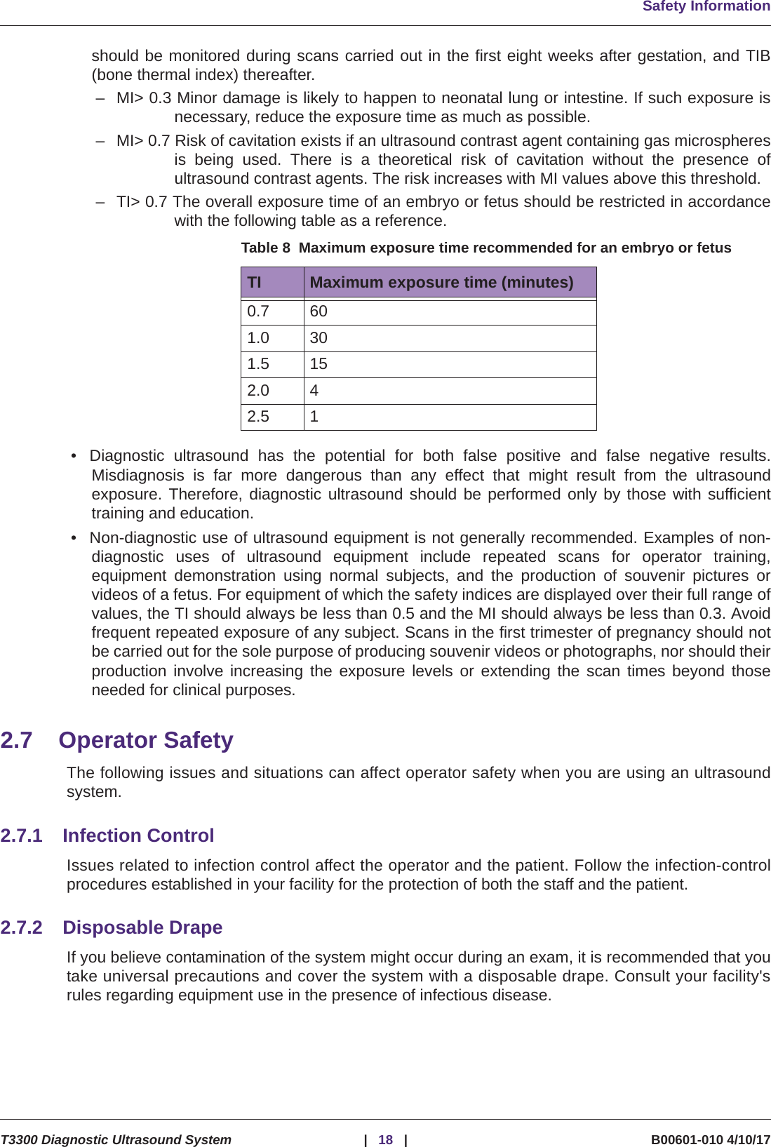
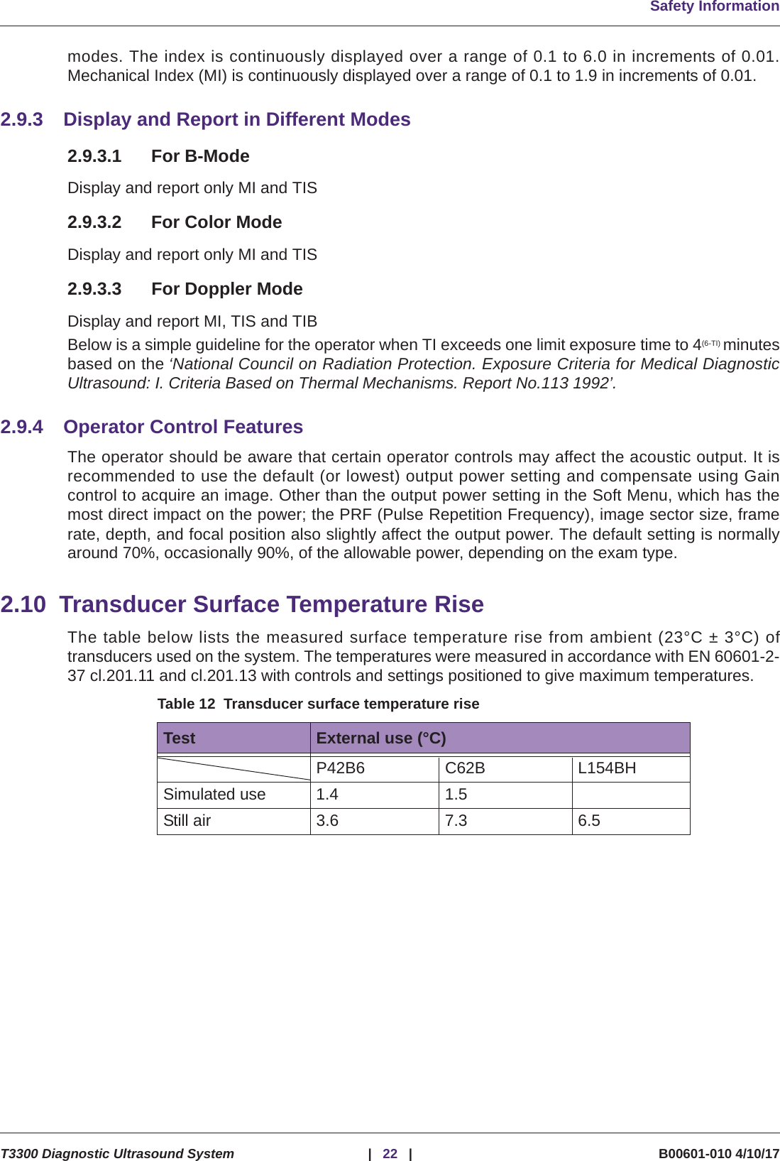
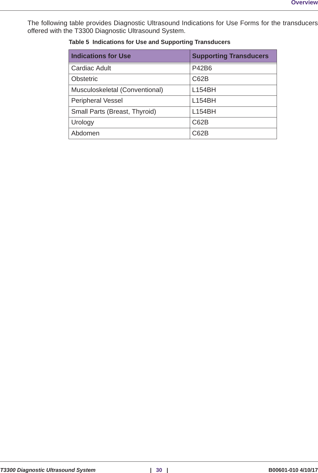
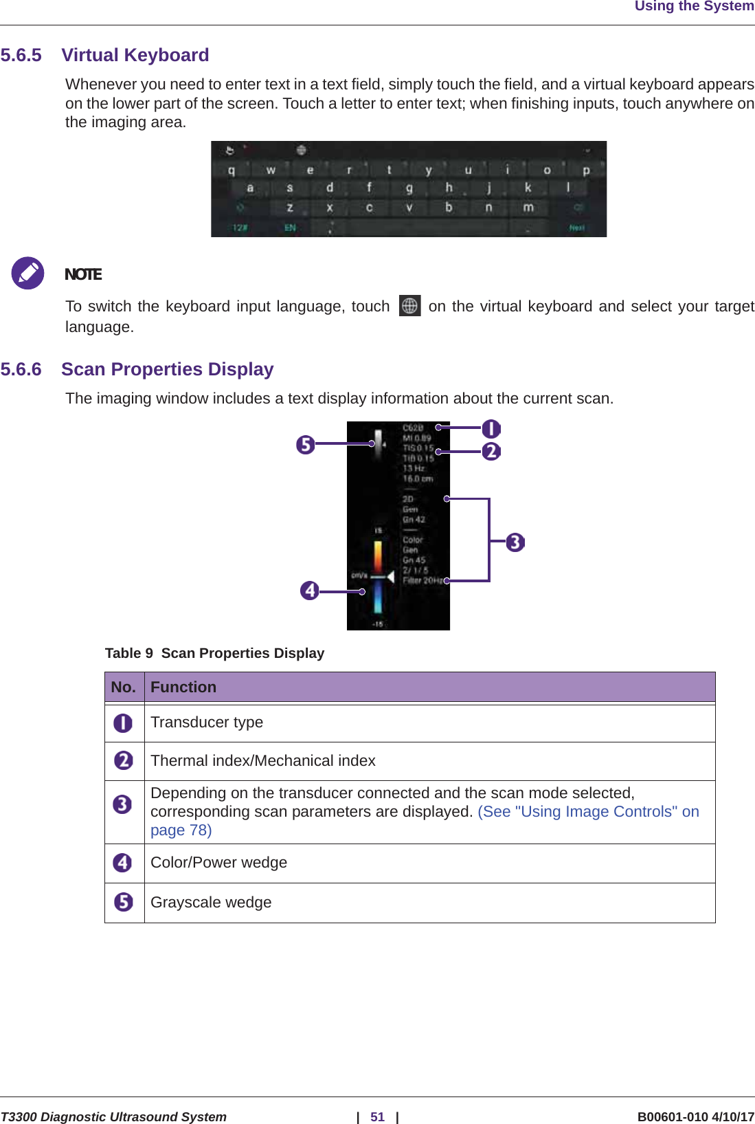
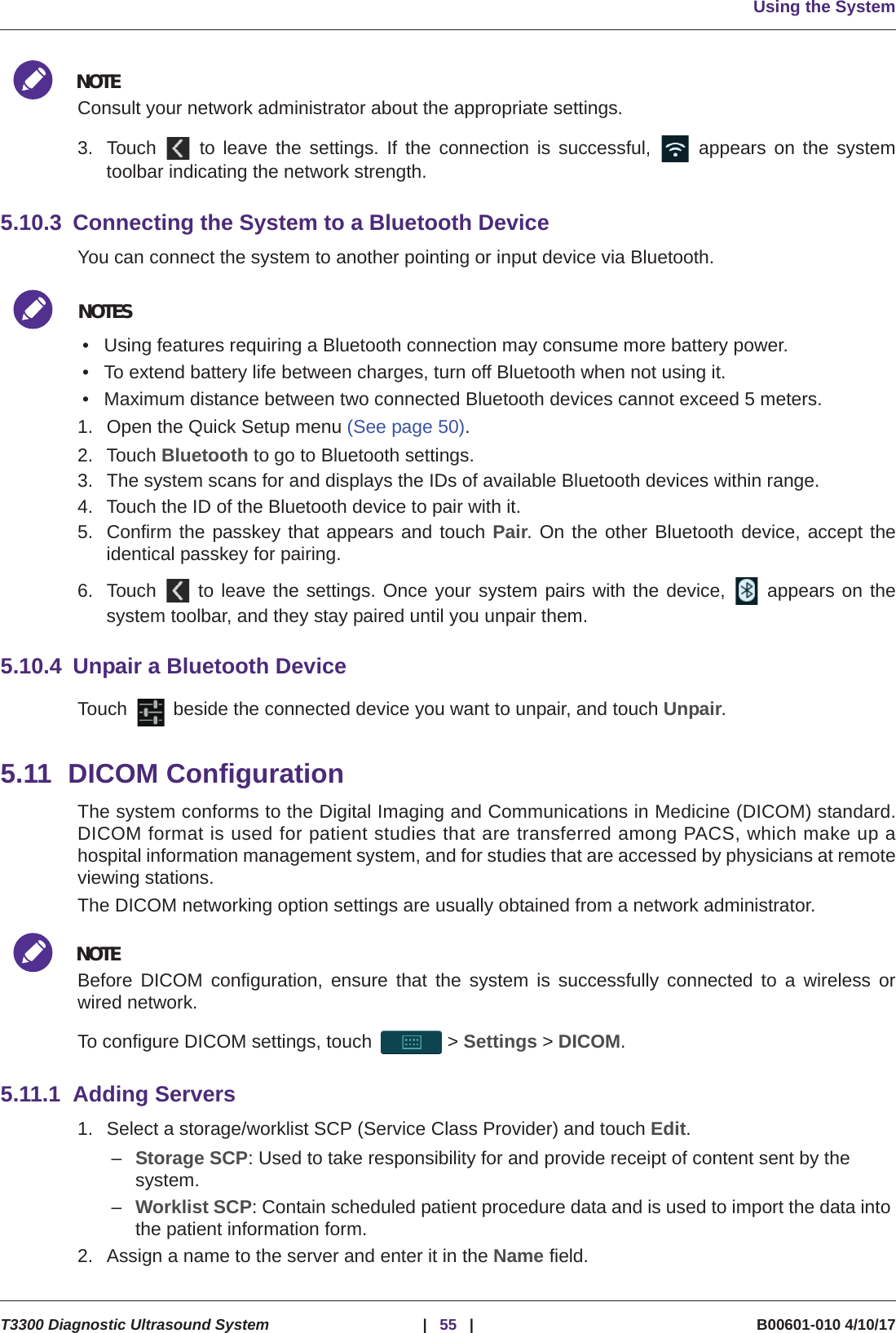
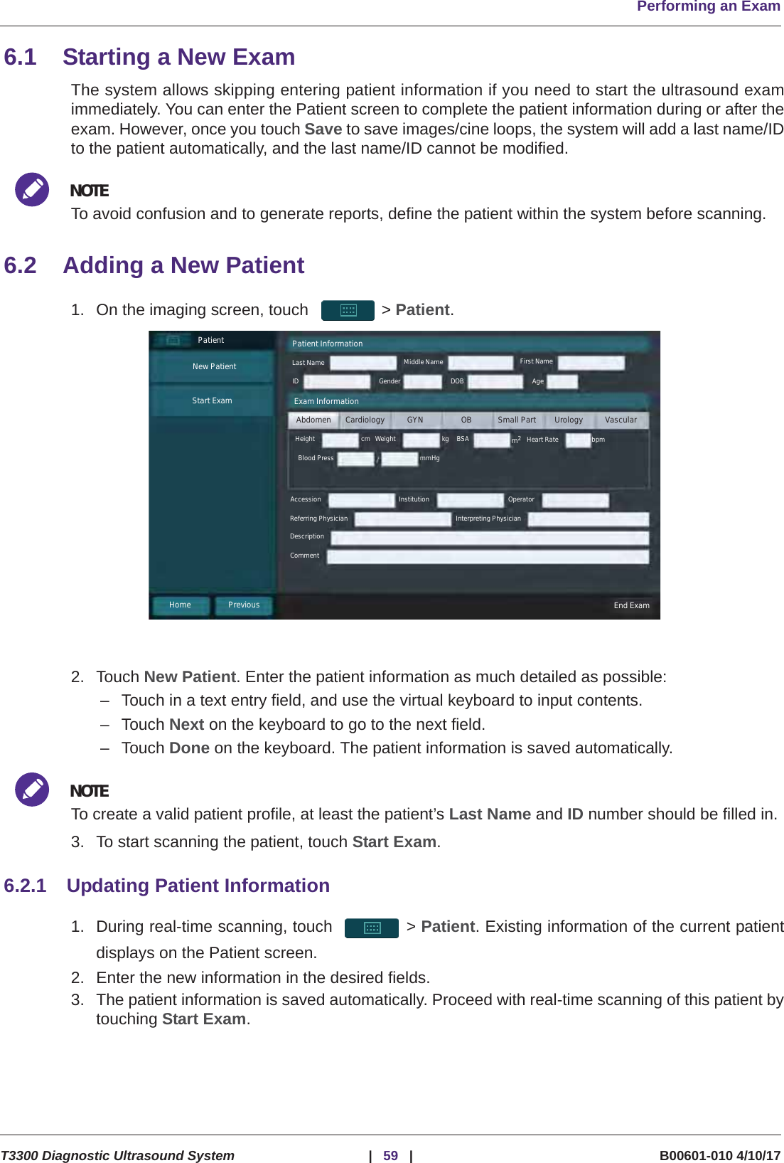
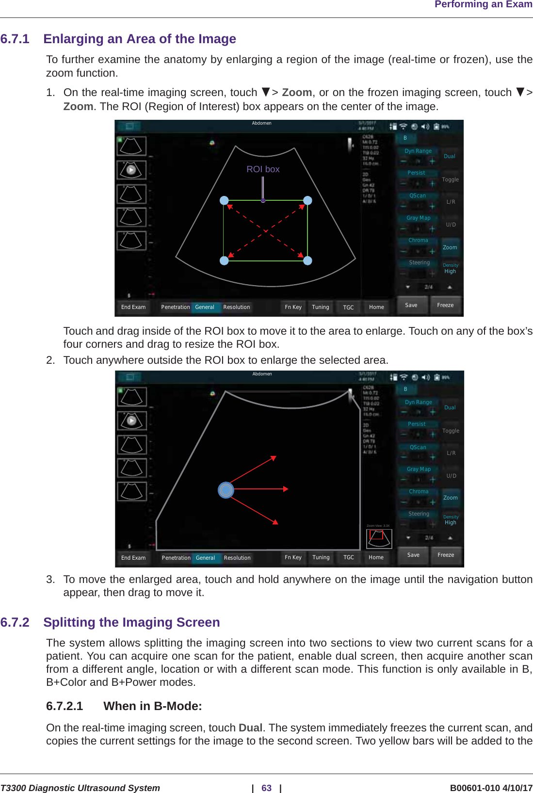
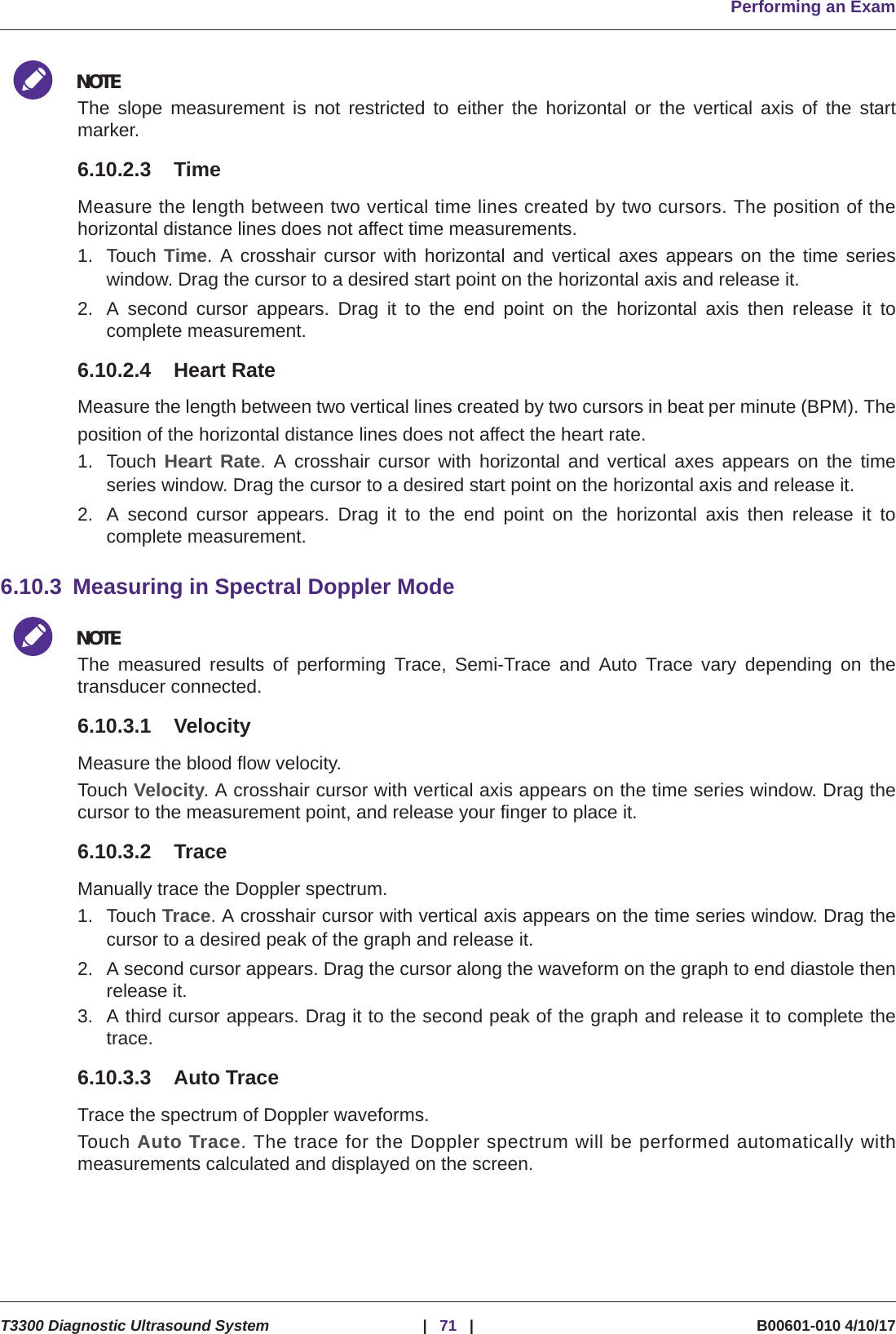
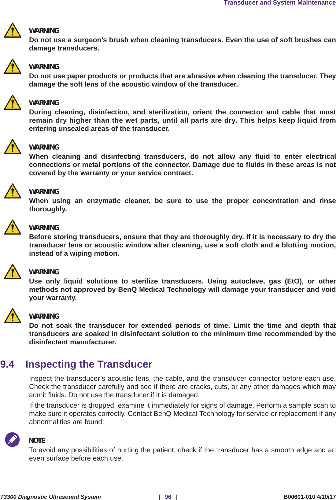
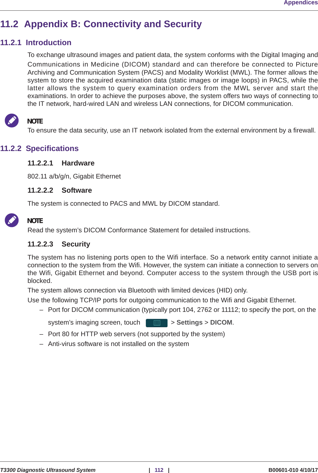
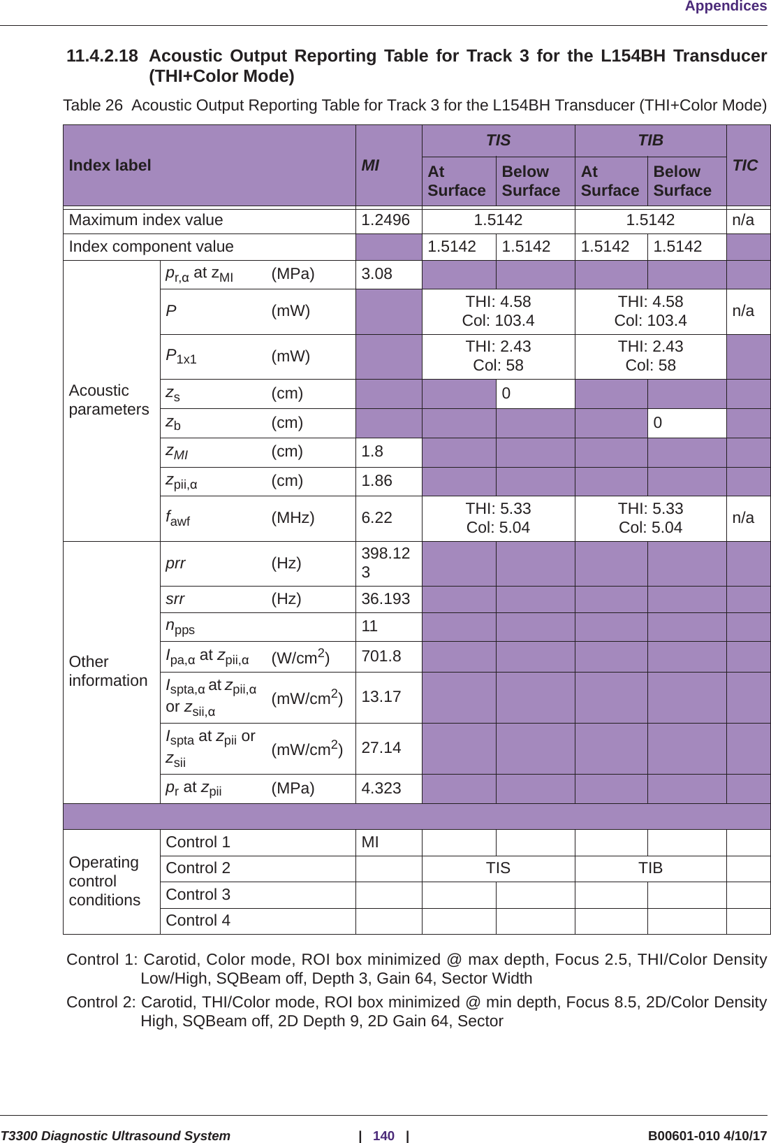
![Safety InformationT3300 Diagnostic Ultrasound System |13 | B00601-010 4/10/17Guidance and Manufacturer’s Declaration - Electromagnetic Immunity - Non-life-supportingEquipmentVoltage dips/Dropout IEC 61000-4-11>95% dip for 0.5 cycle60% dip for 5 cycles30% dip for 25 cycles>95% dip for 5 secondsAs specifiedMains power quality should be that of a typical commercial or hospital environment. If the user of the T3300 Diagnostic Ultrasound System requires continued operation during power mains interruptions, it is recommended that the T3300 Diagnostic Ultrasound System be powered from an uninterruptible power supply or battery.Powerfrequency 50/60 Hz Magnetic field IEC 61000-4-83 A/m As specifiedPower frequency magnetic fields should be that of a typical commercial or hospital environment.Table 6 Guidance and Manufacturer’s Declaration - Electromagnetic Immunity - Non-life-supporting EquipmentImmunity test IEC 60601 test level Compliance level Electromagnetic environment - GuidancePortable and mobile RF communications equipment should be used no closer to any part of the T3300 Diagnostic Ultrasound System, including cables, than the recommended separation distance calculated from the equation applicable to the frequency of the transmitter. Recommended separation distanceConducted RFIEC 61000-4-6 3 Vrms150 KHz to 80 MHz [V1] = 3 VrmsRadiated RFIEC 61000-4-3 3 V/m80 MHz to 2.5 GHz [E1] = 3 V/m 80 MHz to 800 MHz 800 MHz to 2.5 GHzTable 5 Guidance and Manufacturer’s Declaration - Electromagnetic Immunity - All EquipmentImmunity test IEC 60601 test level Compliance level Electromagnetic environment - Guidanced3.5V1----------P=d3.5E2----------P=d7E2-------P=](https://usermanual.wiki/Qisda/T3300/User-Guide-3752865-Page-18.png)