Qixiang Electron Science and Technology 3208UV TWO WAY RADIO User Manual
Qixiang Electron Science& Technology Co., Ltd TWO WAY RADIO Users Manual
Users Manual

A1.140717
INSTRUCTION MANUAL
518UV II

THANK YOU!
transceiver will provide you with reliable, clear and efficient communication service. The
transceiver introduces innovative DSP digital signal processing technology, high degree integration, it is
including kinds of professional function, best stability and great reliability as well as exterior smooth lines,
novel, fashionable, sturdy and durable.
The transceiver is including plenty of TX, RX channels, as well as UU, VV and UV standby modes, can be
single U or V band by operation. It is able to realize cross band function, dual PTT function, 51 groups of
CTCSS encode/decode and 1 group of user-dened CTCSS encode/decode, 1024 groups of DCS encode/
decode, 5TONE encode/decode, DTMF encode/decode, built-in FM radio functions, etc..
It is a meticulous build functional and Multi frequency band radio for radio amateur.
te the frequency and signaling
etc., other wise errors may occur because of different frequency band etc.
CAUTIONS
transceiver is excellent designed with advanced technology. The following tips will be helpful for you in
performing your obligation under warranty and understanding the safety of transceiver usage.
1.Keep the transceiver and accessories away from children.
2.Please do not try to open or modify the transceiver without permission, non-professionals operation may also cause
damage.
3.Please use assorted battery and charger to avoid damage.
4.Please use assorted antenna to ensure the communication distance.
5.Please avoid exposing the radio under the sunshine for a long time or storing it in too hot places. High temperature will
shorten the life of electronic devices.
6.Please avoid storing the radio in the dusty, dirty and damp areas.
7.Please keep the radio dry. Do not wash radio with ardent chemicals and detergents.
8.Do not transmit without antenna.
9.When using this transceiver, we recommend transmitting for 1 minute then receiving for 4 minutes. continuously
transmitting for long time or working in high power will heat the back of the transceiver. Do not place the transceiver's hot
back close to any plastics.
10.If any abnormal smell or smoke coming from the transceiver, please turn off the power instantly and take off the battery
and its case. Then contact local dealers.
NOTE:
All the above tips apply for your transceivers' accessories. If any device can not operate
normally, please contact with local dealers.
If you use any accessories made by other companies, company does not guarantee the
operability and safety of the transceiver.

I
TABLE OF CONTENTS
UNPACKING ................................................................................................................................................................................................ 01
Supplied Accessories ......................................................................................................................................................................... 01
STANDARD ACCESSORIES/ADDITIONAL ACCESSORIES ............................................................................... 02
Standard Accessories .......................................................................................................................................................................... 02
Additional Accessories ........................................................................................................................................................................ 02
BATTERY INFORMATION ................................................................................................................................................................. 03
Charging Operation .............................................................................................................................................................................. 03
Battery Charger Type........................................................................................................................................................................... 03
Notice for Charging Battery .............................................................................................................................................................. 03
How to Charge ........................................................................................................................................................................................ 04
Charging Prompt .................................................................................................................................................................................... 06
How to Store the Battery .................................................................................................................................................................... 06
GETTING ACQUAINTED ................................................................................................................................................................... 07
LCD Display ............................................................................................................................................................................................. 07
BASIC OPERATIONS ........................................................................................................................................................................... 10
Turn the Radio On & OFF ................................................................................................................................................................. 10
Adjusting Volume ................................................................................................................................................................................... 10
Switch between Main band and Sub band ............................................................................................................................... 11
Switch between Channel mode .................................................................................................................... 11
Channel Adjusting ................................................................................................................................................................................. 11
Frequency Adjusting ............................................................................................................................................................................. 11
Frequency Input by Keypad ............................................................................................................................................................. 12
Channel Input by Keypad .................................................................................................................................................................. 12
FM Channel Searching ....................................................................................................................................................................... 13
Squelch Off Momentary / Squelch Off ......................................................................................................................................... 13
....................................................................................................................

II
TABLE OF CONTENTS
Receiving ................................................................................................................................................................................................... 13
Transmitting .............................................................................................................................................................................................. 13
Emergency Alarm .................................................................................................................................................................................. 14
Side Key [PF1] function instruction ............................................................................................................................................... 14
Side key [PF2] function instruction................................................................................................................................................ 15
Edit channel .............................................................................................................................................................................................. 15
Delete channel ........................................................................................................................................................................................ 15
Programming scan ................................................................................................................................................................................ 16
Turn On/Off FM Radio ......................................................................................................................................................................... 17
CTCSS/DCS Setup .............................................................................................................................................................................. 17
CTCSS/DCS Scan ................................................................................................................................................................................ 17
Offset Frequency Direction Setup ................................................................................................................................................. 18
Frequency/Channel Scan .................................................................................................................................................................. 19
Channel Scan Skip ............................................................................................................................................................................... 19
Frequency Reverse .............................................................................................................................................................................. 20
TX Power selection ............................................................................................................................................................................... 20
Stopwatch function................................................................................................................................................................................ 20
DTMF code Transmit and Enquiry ................................................................................................................................................ 21
Keypad lock .............................................................................................................................................................................................. 21
Single-band Switching .........................................................................................................................................................................22
Function Menu Setup .......................................................................................................................................................................... 23
Display Mode Setup ............................................................................................................................................................................. 28
Resume Factory Default .................................................................................................................................................................... 28
TECHNICAL SPECIFICATION ....................................................................................................................................................... 30
TROUBLE SHOOTING GUIDE ......................................................................................................................................................31
01
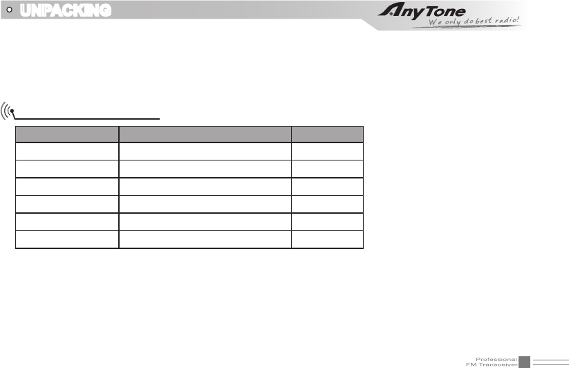
UNPACKING
Please carefully unpack the transceiver. We recommend that you identify the items listed in the following table
before discarding the packing material.
If any items are missing or have been damaged during shipment, please contact with dealers immediately.
Item Number Quantity
Antenna QA11UV 1
Li-ion Battery QB-40L 1
Battery Charger QBC-40L 1
AC Adaptor QPS-07 1
Belt Clip BC09 1
Instruction Manual 1
Supplied Accessories
02
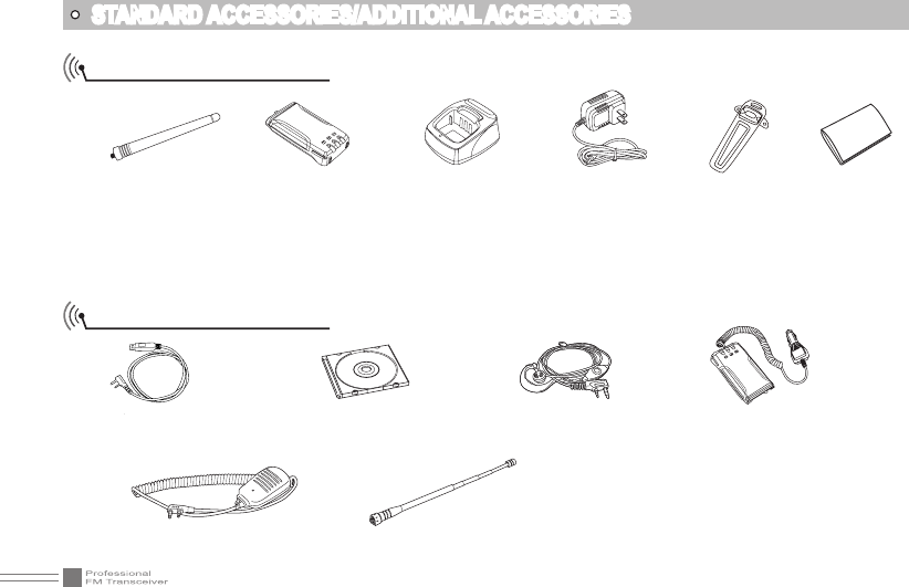
STANDARD ACCESSORIES/ADDITIONAL ACCESSORIES
Standard Accessories
Additional Accessories
Antenna*1
QA11UV
155/435MHz
*1.Note: For frequency band of antenna, please refer to label indicated in the bottom of the antenna.
Li-ion Battery
QB-40L
Instruction
Manual
USB Programming
Cable PC03
Programming Software
QPS518UV_1.01
Earphone
HS03
Handheld Microphone
QHM22
Battery Charger
QBC-40L
Belt Clip
BC09
Battery Pack for Car
Charger CPS05
Telescopic antenna
QA10UV
AC Adaptor
QPS-07
03
BATTERY INFORMATION
Charging Operation
The battery is not charged at the factory, please charge it before use. Charge the battery for the rst time
after purchase or extended storage (more than 2 months) may not bring the battery to its normal operating
capacity. After repeating fully charge/discharge cycle for two or three times, the operating capacity will
reach the best performance. The battery life is over when its operating time decreases even though it is
fully and correctly charged. Replace the battery.
Battery Charger Type
Please use our company's designated charger, other models may cause explosion and injure people. After
installing the battery, if the radio red light twinkles and remind changing battery, please charge the battery.
Notice for Charging Battery
Do not shortcircuit our company designated charger. Never attempt to remove the casing from the ▲
battery, we show no responsibility on the faulty caused by modifying freely without permission of our
factory.
The ambient temperature should be between 5 ▲℃ and 40℃ in charging. Charging outside this range
may not fully charge the battery.
Always switch off the transceiver equipped with a battery before charging. Otherwise, it will interfere ▲
with correct charging.
To avoid interfering the charging procedure, please do not cut off the power or take out the battery ▲
during charging.
04
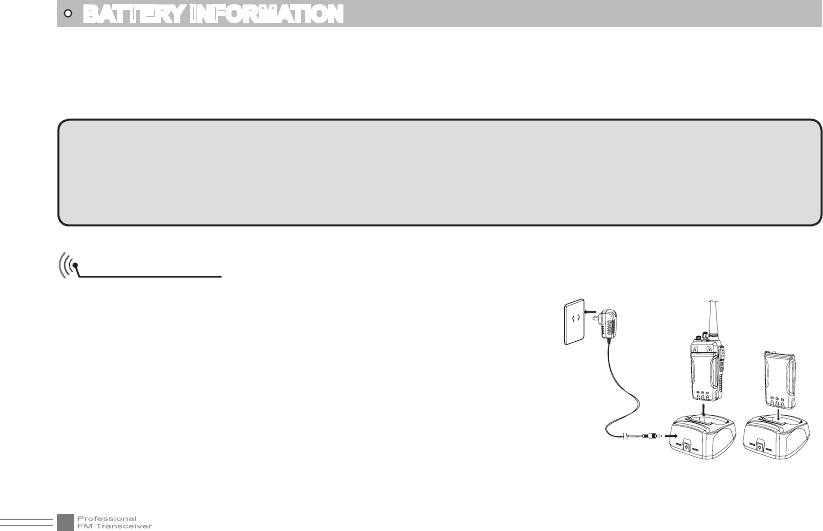
How to Charge
1.Plug the AC adaptor into the AC outlet, then plug the cable of
AC adaptor into the DC jack, the indicator lights orange for 1s
and turns into GREEN---waits to charge.
2.Slide the battery or transceiver with battery into the charger;
make sure the battery terminals are in contact with the
charging terminals well. LED turns into twinkling RED---pre-
charging begins.
3.Pre-charging for about 5 minutes, LED twinkles stop then
charging begins.
4.It takes about 4 hours to fully charge the battery, when LED
turns into GREEN — full charged.
BATTERY INFORMATION
WARNING:
When keys or ornamental chains and other electric metals contact with the battery terminals, the battery
may cause damage or hurt bodies. If the battery terminal short circuit, it will generate a lot of heat, please
be careful when you bring or use the battery, please put battery or radio into insulated container. Do not put
it into metal container.
Do not recharge the battery if it is already fully charged. This may shorten the life of the battery or ▲
damage the battery.
Do not charge the battery or transceiver if it is damp. Dry it before charging to avoid danger. ▲
05
NOTE: When charging a power-on transceiver equipped with battery, the LED will not turn into green to
show the full charge status. Only when turn off the transceiver, the LED can indicate normally.
Because when the transceiver is power on, it would consumes energy, the charger cannot detect when battery
has been fully charged, the charger will charge battery in voltage consumption and fail to indicate correctly.
BATTERY INFORMATION
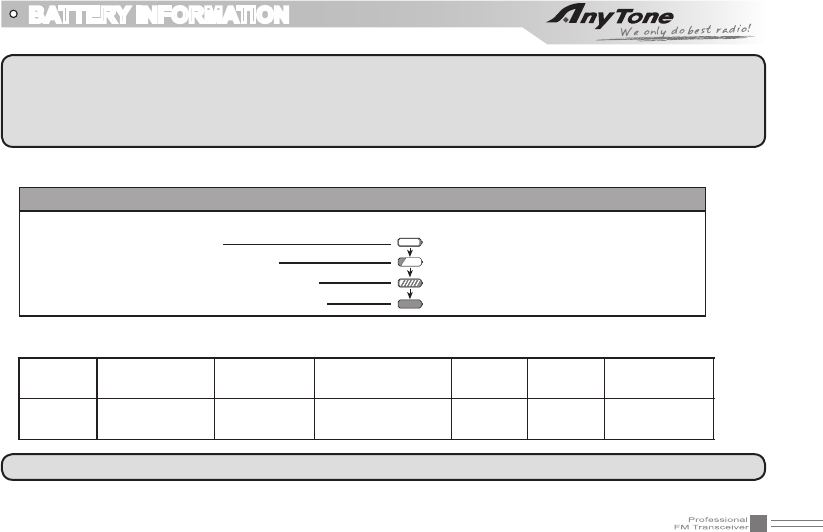
Status LED
STATUS self-examine
when power on (No battery) Pre-charging Charge
normally
Full
Charged Trouble
LED Orange
(for 1 second) Green Red light twinkles
for 5 minutes Red Green Red twinkles
for a long time
5.Charging Process:
6.LED Indicator:
Standby (self-examine orange lights
1second when power on)
Pre-charging (pre-charging stage)
Charging (charge in constant currency)
Full charged (charge in constant voltage)
Green light
Red light twinkles for about 5 minutes
RED light lightens for about 4 hours
Green light
NOTE: Trouble means battery heating, battery short-circuit or charger short-circuit.
06
How to Store the Battery
1.If the battery needs to be stored for a long
period, the battery should be removed
from the radio. It's state of charge should
be 50-100% charged.
2.It should be kept in low temperature, dry
environment.
3.To keep away from hot places and direct
sunlight.
Charging Prompt
1.Self-examination: When charging, ORANGE light twinkles for 1 second and goes out. That means the
charger has passed its self-examination and it can charge the battery normally. If the light remains
orange or the red light twinkles, which means the charger can not pass its self-examination or charge
the battery.
2.Trickle pre-charging: When the battery has been inserted into the charger and red light twinkles, which
means the remnant voltage is low, the charger trickle charge the battery (pre-charging status), until the
battery reaches a certain electric quantity, the charger automatically turns into normal charging. And
if the red light stop twinkling, which means the remnant voltage meets a certain electric quantity, the
charger will charge the battery normally.
BATTERY INFORMATION
NOTE:The time for Trickle pre-charging is not exceed 30m. After 30m, the red indicator is still twinkling,
it means it is unable to charge battery. Please kindly check battery and charger.
WARNING
▲Do not short circuit battery terminals.
▲Never attempt to remove the casing from the battery
pack.
▲Never assemble the battery in dangerous surroundings,
spark may cause explosion.
▲Do not put the battery in hot environment or throw it
into fire, it may also cause explosion.
07
GETTING ACQUAINTED
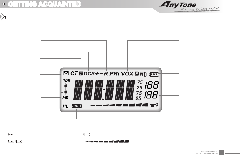
LCD Display
On LCD display screen, you will see various icons which stand for the selected functions and sometimes
you may forget the meaning of them. Here you will nd the following table extremely useful.
Frequency
Reverse
Offset Frequency
DCS
Optional Signaling
CTCSS
FUNC Icon
The arrow points to
main channel
FM radio
TX Power
Busy Channel
VOX Function
Scan Skip
Narrow band
Battery Capacity
Function Menu
Number, Channel
Number
FM Channel Number
channel Number
Keypad Lock
NOTE:
Battery capacity indicator(full) No power, replace battery pack or charge battery
Real time display receiving signal
strength/Power Indicator
Battery capacity remnant
08
GETTING ACQUAINTED
1
3
2
7
8
5
9
6
4
1
8
7
C
D
FM
FUNC
MAIN
V/M
ESC
SCAN
TONE
REV
SET
S.W
10
09
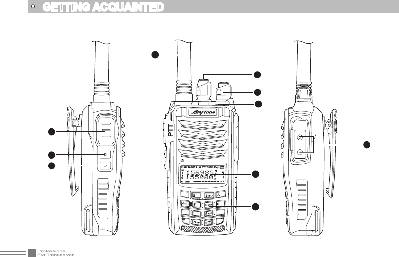
GETTING ACQUAINTED
1 Antenna
2 Selector Knob
3 Power / Volume Switch
Rotate it clockwise to turn on transceiver, rotate it anticlockwise until heard "click" to turn off the
transceiver.
When transceiver is power on, rotate it clockwise to increase volume, anticlockwise to reduce volume.
4 TX/RX indicator, RX is GREEN, TX is RED
5 LCD display
Displays current frequency/channel and operations
6 Keypad
Enters desired frequency/channel or operations by keypad
7 PTT key
Press PTT key to talk, release this key to receive.
8 PF1 key
9 PF2 key
10 Speaker/Microphone jack, programming software jack
10
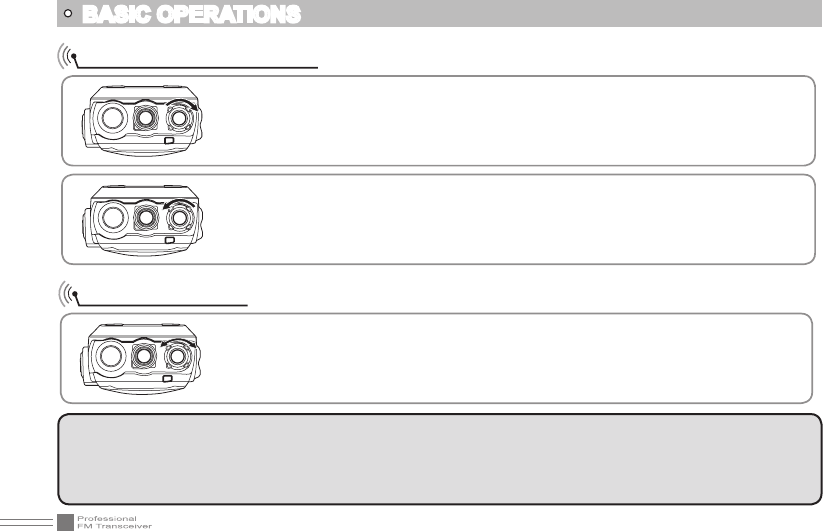
Turn the Radio On & OFF
NOTE:
Press the side key programmed as Squelch Off Momentary to monitor the background noise. Turn [POWER]/
[VOLUME] to control the volume. The volume you need can be adjusted more correctly when communicating
with the other party.
BASIC OPERATIONS
Under power-off state, please turn [POWER]/[VOLUME] clockwise to turn on the
transceiver.
Under power-on state, please turn [POWER]/[VOLUME] anticlockwise to turn off
the transceiver.
Under power-on state, turn [POWER] /[VOLUME] to adjust volume. Clockwise-up,
anticlockwise -down.
When adjusting the volume, user can press the key programmed as Squelch Off to
monitor current volume rstly.
Adjusting Volume

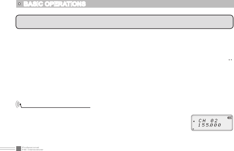
11
Switch between Main band and Sub band
Under standby state, press key to switch channel between Main band and Sub
band. Arrow directs the current operational channel.
Switch between Channel mode
Under standby state, press key to set main band as Channel mode
.
NOTE: In transceiver mode, arrow directs the main band channel.
If there is a null channel between two channels, transceiver will skip null channel, enter into next channel
directly.
BASIC OPERATIONS
Channel Adjusting
When transceiver in Channel mode or FM radio channel mode, rotate channel switch to adjust channel.
Rotate channel switch clockwise to enter the downward channel, anticlockwise to enter the upward
channel
12
BASIC OPERATIONS
NOTE: Channel step:2.5K) 5K) 6.25K) 10K) 12.5K) 20K) 25K) 30K and 50KHz in total 9 for optional. FM
radio step frequency is 50K.
Channel Input by Keypad
Under channel mode of transceiver or FM radio, you can switch to desired channel
by entering three numbers (001-199). If the entered channel is not in edited channel
range, the transceiver will emit beep to prompt wrong input and return to current
channel. For example, entering 001 is channel 1, 030 is channel 30, 125 is channel
125.
13
BASIC OPERATIONS
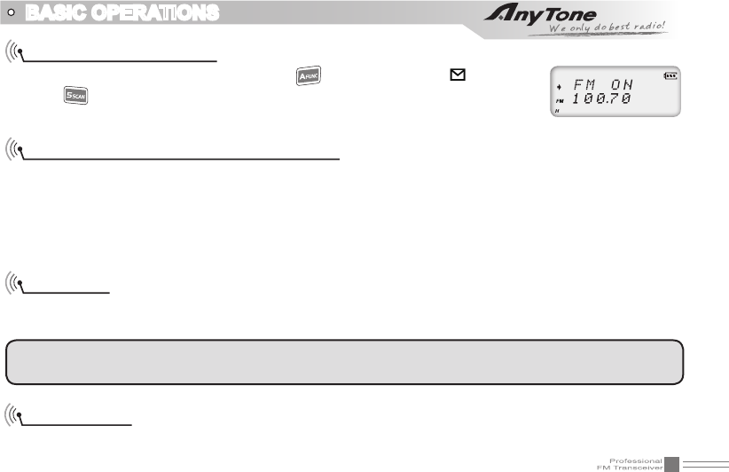
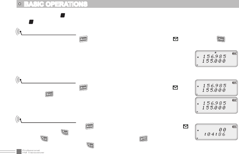
FM Channel Searching
When transceiver in FM radio mode, press key, LCD displays " " icon, then
press to start FM searching. When one station is sought, LCD displays current
station frequency, you can listen to current station.
Squelch Off Momentary / Squelch Off
Side key [PF2] can be setup for Squelch off Momentary or Squelch off function by programming software.
1.Squelch off: Press [PF2] key, squelch circuit is not mute, back-ground noise can be heard. Press [PF2]
key again, squelch circuit is mute.
2.Squelch off Momentary: Press and hold [PF2] key, squelch circuit is not mute, back-ground noise can be
heard. Release [PF2] key, squelch circuit is mute.
Receiving
When your transceiver is called by other party, the green LED light will be on and the arrow icon will ash,
you can hear the calling.
NOTE: You may not receive the calling when your transceiver is set at high squelch level. If current channel
is programmed with decode signal, only the same signaling call can be heard.
Transmitting
According to [PF2] key setup in programming software, hold [PF2] key to monitor the channel to ensure
14
BASIC OPERATIONS
Emergency Alarm
Under standby state, press and hold [PF1] key which is programmed with ALARM function until LCD
displays "ALARM", Emergency alarm function is started. This transceiver has 4 Alarm modes for optional,
can be setup in programming software. Power off transceiver to exit Alarm.
Side Key [PF1] function instruction
1. VOLT: Battery capacity inquiry: Under standby, press [PF1] key, LCD displays current battery capacity,
press this key again to exit.
2. CALL: Transmit the prestored DTMF/5TONE Encode signal in channel.
3. ALARM: Long pressing [PF1] key, LCD display "ALARM", transceiver will enable the preset alarm function.
4. SUBPTT: Press [PF1] key, transceiver will transmit at sub-band frequency.
5. Transmit tone pulse frequency: Press and hold [PTT] key, then press [PF1] key to transmit selected
tone pulse frequency.
NOTE: The tone pulse frequency can be set to 1750Hz, 1450Hz, 1000Hz or 2100Hz in Function menu No.28
TBST.
it is not busy, press [PTT] key and talk to speaker.
Please keep the distance between mouth and speaker to be 2.5-5CM, speak in normal tone to get the
best acoustic delity.
NOTE: When press and hold PTT key, transceiver is transmitting if the red LED light is on, release [PTT]
key to receive calls.
11
Switch between Main band and Sub band
Under standby state, press key to switch channel between Main band and Sub
band. Arrow directs the current operational channel.
Switch between Channel mode
Under standby state, press key to set main band as Channel mode
.
NOTE: In transceiver mode, arrow directs the main band channel.
If there is a null channel between two channels, transceiver will skip null channel, enter into next channel
directly.
BASIC OPERATIONS
Channel Adjusting
When transceiver in Channel mode or FM radio channel mode, rotate channel switch to adjust channel.
Rotate channel switch clockwise to enter the downward channel, anticlockwise to enter the upward
channel
16
BASIC OPERATIONS
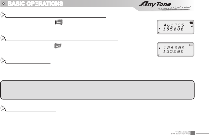
Programming scan
Setup the frequency of L1 channel, U1 channel, L2 channel and U2 channel will realize VFO frequency
scanning border limited. L1 & L2 is starting frequency, U1 & U2 is end frequency. When VFO frequency
between L1~ U1 or L2 ~ U2, transceiver will scan frequencies between L1 ~ U1 or L2 ~ U2. When VFO
frequency is lower than L1 or L2, transceiver will scan frequencies higher than L1 or L2. When VFO
frequency is higher than U1 or U2, transceiver will scan frequencies higher than U1 or U2.
1. In VFO mode, enter desired frequency and relative setup, press key, the top left corner of LCD
displays " " icon, then press key switch into channel mode, channel number ashes.
2. Rotate channel switch to choose desired channel number.
3. Press key, the top left corner of LCD displays " " icon, then press key until transceiver emits
"DUDU" beep, channels are saved successfully.
NOTE: This process can be applied for deleting FM radio channels.
NOTE: To make this setup, L1 and U1 must in same frequency band. L2 and U2 must in same frequency
band.
switch into channel mode, channel number ashes.
2. Rotate channel switch to select desired deleting channel number.
3. Press key, the top left corner of LCD displays " " icon, press and hold key until transceiver
emits "DUDU" beep and clear up frequency information of current channel, deletion is successful.
17
BASIC OPERATIONS
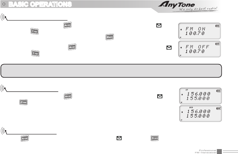
Turn On/ Off FM Radio
Under standby state, press key, the top left corner of LCD displays " " icon,
then press key, LCD displays "FM ON" and current FM radio frequency, FM
radio function is on. When FM radio is on, press key, LCD displays "FM OFF",
FM radio is mute.
When FM radio is on, press key, the top left corner of LCD displays " "
icon, press key to turn off FM radio and return to transceiver state. Re-start
transceiver also can exit FM radio function.
NOTE: To use FM radio function, user must set RADIO function on 30th menu to be ON, otherwise can not
use FM radio function normally.
CTCSS/DCS Setup
Under standby state, press key, the top left corner of LCD displays " " icon,
press key, LCD displays "CT" icon, it means current channel add CTCSS signal
function. Repeat above operation, LCD displays "DCS" icon, it means current
channel add DCS signal function. Repeat above operation, "DCS" icon disappears,
current channel without CTCSS/DCS signal.
CTCSS/DCS Scan
Press key, the top left corner of LCD displays " " icon, press key to enter into CTCSS/DCS
scan. Under this state, rotate channel switch to change scan direction. When scan the matching CTCSS/
18
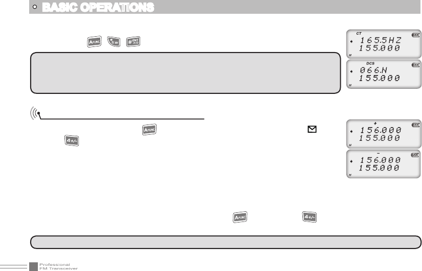
Offset Frequency Direction Setup
Under standby state, press key, the top left corner of LCD displays " " icon,
press key to choose offset frequency direction. There are 3 options, Positive
offset, Minus offset, shut off offset.
1. (+) Positive offset: Indicates TX frequency is higher than RX frequency. When
enable reverse function, the RX frequency is higher than TX frequency.
2. (-) Minus offset: Indicates TX frequency is lower than RX frequency. When enable
reverse function, the RX frequency is lower than TX frequency.
3. None: Indicates shut offset off.
Under frequency mode (VFO) or channel mode, press key then press key to choose positive offset
direction(+), minus offset direction (-) , shut offset off one by one (Please refer to offset frequency setup).
NOTE: This function is invalid when transceiver works in professional mode or the
arrow directed channel no setting CTCSS/DCS signaling.
In current channel, if signaling set as CTCSS, it will scan CTCSS, if sets as DCS,
will scan DCS.
NOTE: This function is invalid in professional transceiver mode.
DCS signaling, it will stay 5seconds and then go on scanning. Press any other
keys except , , key to exit.
BASIC OPERATIONS
19
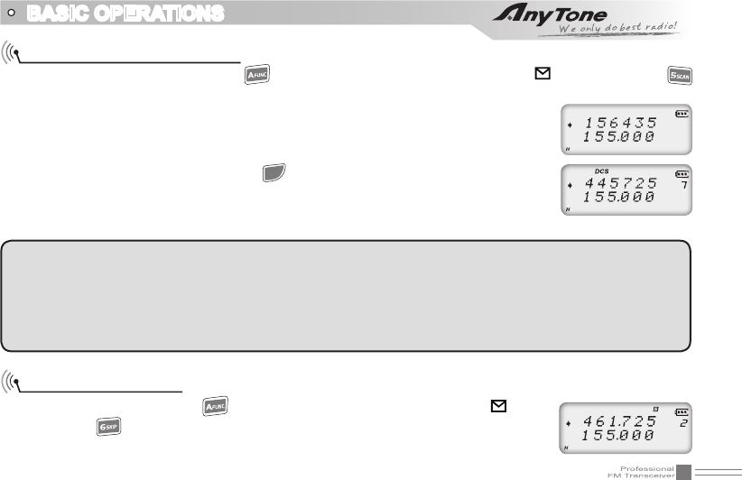
Channel Scan
Under corresponding mode, press key, the top left corner of LCD displays " " icon, then press
key to start frequency scan or channel scan.
1. Channel Scan
Under channel mode, this function is used for monitoring signal of each channel
in this mode. Press numeric key or key to exit.
▼
▼
▼
NOTE:
Frequency scan is of all bands scan) it scans upwards as your STEPPING setting.
In channel scan) the skipped channel is not in the line of scanning. Scan upwards as per channel no.
(please refer to channel scan skip).
Channel scan can change scan direction by rotating channel switch) when find a matching carrier
wave and signaling) the transceiver will stay 5 seconds then go on scanning. (Please refer to scan setup)
Channel Scan Skip
Under channel mode, press key, the top left corner of LCD displays " " icon,
then press key to set current arrow directed channel as Channel scan skip.
Repeat above operation to cancel channel scan skip.
BASIC OPERATIONS
20
1. LCD displayed "
S
" means the current channel will not be scanned.
2. "
S
" icon disappeared means the current channel will be scanned.
Frequency Reverse
Under standby state, press key, the top left corner of LCD displays " " icon, then press key to
set arrow directed channel as frequency reverse, repeat above operation to turn off frequency reverse.
1. When LCD displays "R" icon, it means current arrow directed channel open the
frequency reverse function, the TX frequency and RX frequency is interchanged,
if CTCSS/DCS signaling is set, it will also interchange.
2. When "R" icon disappears, it means reverse function is close.
TX Power selection
Under standby state, press key, the top left corner of LCD displays " " icon,
then press key to choose High/Low power for current arrow directed channel.
1. When LCD displays "L" icon, it means low power is chose.
2. When LCD displays "H" icon, it means high power is chose.
Stopwatch function
1. Under standby state, press key, the top left corner of LCD displays " "
icon, then press to enter into stopwatch function.
2. Press key to start timing. Under this state, press key to pause timing.
When timing is pause, press key to continue timing.
BASIC OPERATIONS
21
3. Press [PF1], [PF2] or key to exit stop watch function.
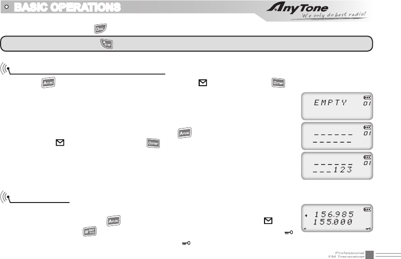
DTMF code Transmit and Enquiry
1. Press key, the top left corner of LCD displays " " icon, then press key, LCD displays DTMF
data and group number (total 16 groups) of current group.
2. Rotate channel switch to choose desired group and DTMF data, press PTT key
to transmit selected DTMF signaling. If current group not edit DTMF data, LCD
displays "EMPTY".
3. When current group displays "EMPTY", press key, the top left corner of LCD
displays " " icon, press and hold key until transceiver emits "DU" beep,
transceiver enters into DTMF edit state, LCD displays "___________", now you
can enter desired DTMF data by keypad.
4. When nished editing, press side key [PF2] to save DTMF signaling.
Keypad lock
In order to prevent wrong operation, user can make use of keypad lock function.
Under standby state, press key, the top left corner of LCD displays " " icon,
then press and hold key until transceiver emits "DU" beep, LCD displays " "
icon, keypad is locked. Repeat above operation, " " icon disappears, key lock function is cancelled.
NOTE: During timing, press key to stop timing and displays current data, press this key again to clear timer.
BASIC OPERATIONS
22
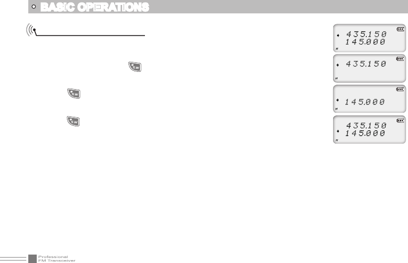
Single-band Switching
To avoid interference from the sub channels when main channel in use, you can
use the single band switching function to turn off sub channel band quickly.
1. In standby mode, press key, the radio will display the upper band, the lower
band will be turned off.
2. Press key again, the radio will display the lower band, the upper band will
be turned off.
3. Press key again to return to dual band display.
BASIC OPERATIONS
23
Menu 1-13 of this transceiver are channel operations. Channel operations temporarily changed the functions
of current channel. When power off or channel has been changed, the relevant setup will be erased.
The operating methods are as follows:
1. Press key, the top left corner of LCD displays " " icon, then press key to enter function menu.
2. Press / key to choose desired function.
Note:When setup CTCSS/DCS encode and decode) press key to choose CTCSS) DCS or off. If choose
DCS) press key to switch positive code or reverse code.
3. Rotate channel switch to choose desired setting.
4. Press key or key to conrm and exit.
If you need detailed operation, please download complete user manual from our website (www.
qxdz.cn), or call our service department.
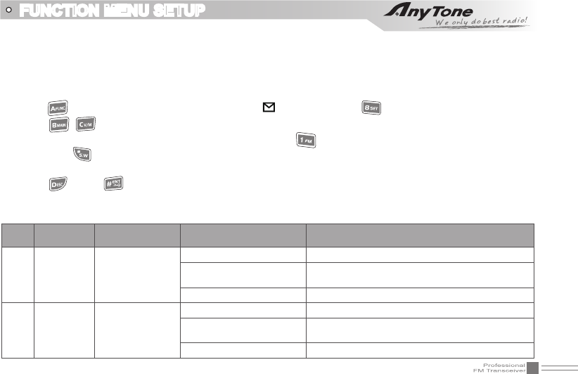
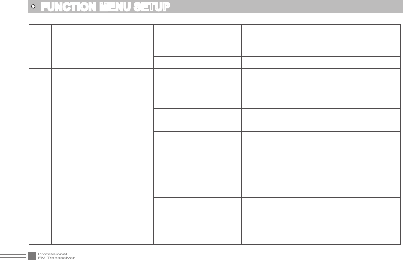
FUNCTION MENU SETUP
Menu
No.
LCD Display
Function Options Description
1T-CDC CTCSS/DCS
Encode
OFF No CTCSS/DCS Encode
62.5HZ-254.1Hz+Self dened 51 groups xed CTCSS encode+1 group self-
dened encode
000N-777I 1024 groups DCS Encode
2R-CDC CTCSS/DCS
Decode
OFF No CTCSS/DCS Decode
62.5HZ-254.1Hz+Self dened 51 groups xed CTCSS decode+1 group self-
dened decode
000N-777I 1024 groups DCS decode
24
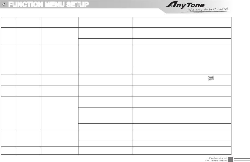
FUNCTION MENU SETUP
3 RT-CDC
CTCSS/DCS
Encode/Decode
Synchronous
OFF No CTCSS/DCS encode/decode
62.5HZ-254.1Hz+Self dened 51 groups xed CTCSS encode/decode + 1 group
self-dened CTCSS encode/decode
000N-777I 1024 group DCS encode/decode
4 TONDEC Optional signaling
setup DTMF Current optional signal is DTMF.
5 SIGNAL Squelch mode
setup
SQ
When current channel received matching RF
signals, transceiver can hear the talking from the
other party.
CTCSS/DCS
When current channel received matching RF signals
and matching CTCSS/DCS signaling, transceiver
can hear the talking from the other party.
TONE
When current channel received matching
RF signals and matching optional signaling,
transceiver can hear the talking from the other
party.
CT&TO
When current channel received matching RF
signals + matching optional signaling + matching
CTCSS/DCS signaling, transceiver can hear the
talking from the other party.
CT/TO
When current channel received matching RF
signals, or matching optional signaling, or matching
CTCSS/DCS signaling, transceiver can hear the
talking from the other party.
6 STEP Frequency step
size setup 2.5K-50K 9 options in total
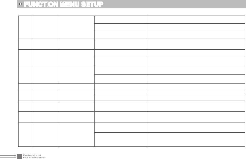
25
7 W/N Wide / Narrow
Band Selection 25K/12.5K Wide band/Narrow band
8 REV Frequency
Reverse
ON Turn on Frequency reverse function, TX and RX
frequency of current channel will be interchanged.
OFF Close Frequency reverse function.
9 TALKAR Talk Around TX=RX
Turn on Talk Around function, current channel will
transmit at RX frequency, if CTCSS/DCS signaling
is set, it will interchange decoding CTCSS/DCS as
encoding.
OFF Close Talk Around function.
10 OFFSET Offset Frequency
setup 0-70MHz Frequency range is 00-70MHz. Press key, the
offset frequency can be adjusted by MHz step.
11 NAME Editing Channel
name a-Z In channel name display mode, will display the
edited channel name.
12 RPLOCK Busy Channel
Lockout
BUSY Carrier wave lock, transmitting is prohibited when
received matching carrier wave.
REPEAT
Signaling lock, transmitting is prohibited when
received matching carrier but with mismatching
CTCSS/DCS
OFF Close BCLO function.
13 TX TX OFF ON TX function is enabled in current channel.
OFF TX function is disabled in current channel.
14 BAND Band Limit ON/OFF Turn on/off band limit function.
FUNCTION MENU SETUP
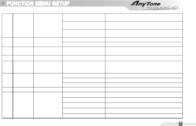
26
15 DSPSUB Sub band display
setup
FREQ Display sub band frequency or channel
VOLT Display current battery voltage
OFF Sub band display is disabled
16 BEEP Keypad Voice
prompt setup ON/OFF Turn on/off keypad voice prompt function
17 TOT Time-Out-Timer
OFF Turn off time-out timer
10-270S Total 27 levels of TOT for optional, each interval is
10S
18 VOX
Voice Operated
Transmission
(VOX) Setup
OFF Turn off VOX function
1-10 Total 10 VOX levels for optional
19 VDELAY VOX Delay Setup 0.5S-3S Total 27 levels for optional, each interval is 0.1S
20 APO Automatic Power
Off Setup
OFF Disable the Automatic power off function
30MIN-2HOUR 30minutes ~ 2hours: Total 3 levels for optional.
21 DTMF DTMF
Transmitting Time 50MS-500MS Total 5 kinds of DTMF transmitting time for
optional.
22 SQL Squelch level
Setup 00-09 10 levels of squelch in total for optional, "00" is minimum
setup value (normally open)
23 SCAN Scan Dwell Time
Setup
5ST-15ST When scanning matched signal, transceiver will
stop scanning for 5-15seconds then resume.
2SP
When scanning matched signal, transceiver will stop
scanning, 2seconds after signal disappeared, then
resume.
FUNCTION MENU SETUP
27
24 FTIME Function Icon
Stay Time
FUNCT When nished function setting or enter into
function menu, icon disappeared.
1SEC-3SEC When nished function setting or enter into function
menu, icon stay 1-3seconds then disappeared.
ALWAYS Function icon is always display, only when pressing
function key again, the icon will disappear.
25 LIGHT LCD Backlight ON/OFF Always on/off
AUTO Backlight will automatic closed after a period.
26 COLOR LCD Backlight
Color BLUE/ORG/PUR Blue/Orange/Purple
27 ID Self ID inquiry *** LCD displays radio self ID, DTMF ID is 3 digits.
28 TBST
Tone Pulse
Frequency
Selection
1750Hz/2100Hz/1450Hz/
1000Hz
Tone plus frequency is 1750Hz/2100HZ/1450Hz
/1000Hz
29 SAVE Battery Save
Setup
OFF Turn off battery save function.
1:2-1:8 Battery save time is 1:2-1:8
AUTO Battery save ratio is adjusting automatically.
30 RADIO FM radio ON/OFF Allow/Prohibit using FM radio.
31 PF1 Self dene PF1
key function
VOLT Displays current battery capacity.
CALL Call function.
ALARM Emergency alarm function.
SUBPTT Sub band PTT.
OFF No function.
FUNCTION MENU SETUP
28
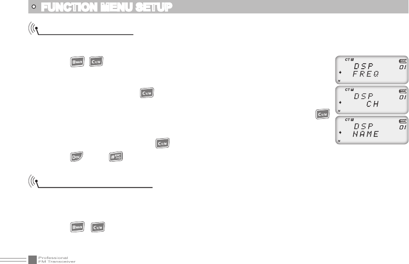
Display Mode Setup
There are three kinds of display modes for optional.
1. Press [PF2] key to turn on radio, hold [PF2] key until transceiver emits beep.
2. Press / key to choose No. 01 function item, it shows "DSP" on LCD.
3. Rotate channel switch to choose desired setup.
FREQ: Frequency + Channel mode, transceiver displays current channel name
+ frequency, press key to switch into VFO mode.
CH: Channel mode, 1~21 items of function menu will hide automatically, user can
only operate some functions. It is unable to switch into VFO by pressing
key. This model can be used for Amateur mode.
NAME: Channel + Name Tag mode, transceiver displays current channel number
+ channel name, press key to switch into VFO mode.
4. Press key or key to con rm and exit.
FUNCTION MENU SETUP
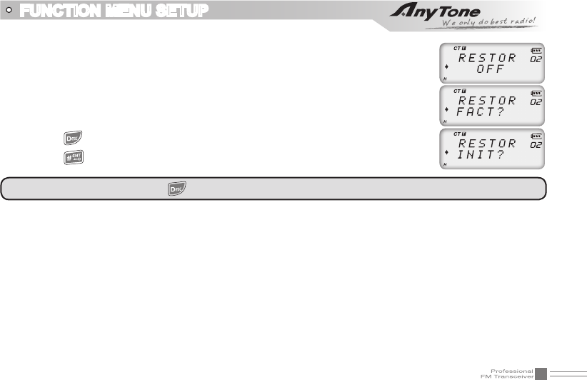
Resume Factory Default
You can make all the settings of transceiver return to the factory default settings when transceiver can not
work normally because of wrong operation or error setup.
1. Press [PF2] key to turn on radio, hold [PF2] key until transceiver emits beep.
2. Press / key to choose No. 02 function item, it shows "RESTOR" on LCD.
3. Rotate channel switch to choose desired setup.
29
FUNCTION MENU SETUP
OFF: No operations.
FACT: Resume all items to factory default, including channel and background
settings.
INIT: Resume background settings to factory default, channel operations are
keeping.
4. Press key to exit current selection.
5. Press key to con rm current selection.
Note: In power off state, hold key to power on radio, the radio will resume to factory default.
30
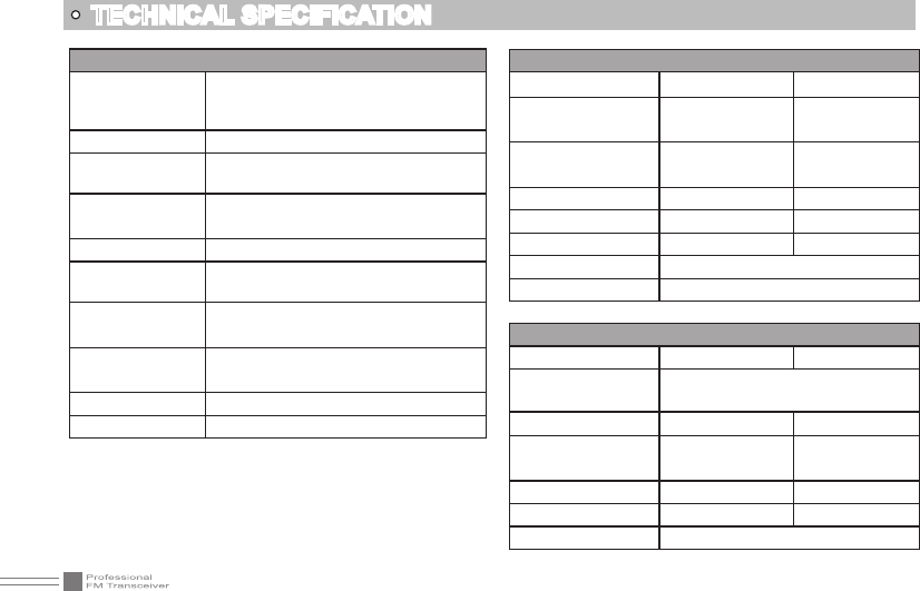
General
Frequency Range
VHF:1 36~174MHz
UHF:400~480MHZ
(EX:400~520MHz)
Channel Capacity 200 channels
Channel Spacing 25KHz (wide band)
12.5KHz (narrow band)
Phase-locked
Step 0.1KHz
Operation Voltage 7.4V DC ±20%
Battery Life More than 12 Hours(1350mAh), by
5-5-90 working cycle
Frequency
Stability ±2.5ppm
Operation
Temperature -20℃~ +55℃
Size 127x61x36.5mm (with battery,antenna)
Weight 235g (with battery, antenna)
TECHNICAL SPECIFICATION
Receiving Part
Wide band Narrow band
Sensitivity
(12dB SINAD) ≤0.25μV ≤0.35μV
Adjacent Channel
Selecitvity ≥65dB ≥60dB
Intermodulation ≥60dB ≥60dB
Spurious Rejection ≥70dB ≥70dB
Hum & Noise ≥45dB ≥40dB
Audio Distortion ≤5%
Audio Power Output 1000mW/10%
Transimitting Part
Wide band Narrow band
Power Output 4W/1W (UHF)
5W/1W (VHF)
Modulation 16KΦF3E 11KΦF3E
Adjacent Channel
Power ≥65dB ≥60dB
Hum & Noise ≥40dB ≥40dB
Spurious Emission ≤-36dB ≤-36dB
Audio Distortion ≤5%
31
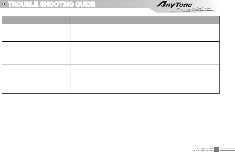
TROUBLE SHOOTING GUIDE
Problem Corrective Action
No power
A.The battery may be exhausting. Recharge or replace the battery.
B.The battery may not be installed correctly. Remove the battery
and install it again.
Battery power dies shortly after
charging. The battery life is nished. Replace the battery pack with a new one.
No sound after using earphone.
for a while Earphone jack is broken. Please contact with local dealers to repair.
Cannot talk or hear other
members in your group
A.Different frequency or channel, please change it.
B.Different CTCSS / DCS / DTMF, please reset it.
C.Out of communication range.
Receiving intermittent with in
big noise Out of communication range or obstruct by tall buildings or in big noise.
The SAR limit of USA (FCC) is 8 W/kg averaged over one gram of tissue. Device
types 518UVII (FCC ID: T4K3208UV) has also been tested against this SAR limit.
The highest SAR value reported under this standard during product certification for
use when properly worn on the body is 2.366 W/kg and for head is 3.990 W/kg.
. This device was tested for typical body‐worn operations with the back of the
handset kept 25mm from the body. To maintain compliance with FCC RF exposure
requirements, use accessories that maintain a 25mm separation distance between
the user's body and the back of the handset. The use of belt clips, holsters and
similar accessories should not contain metallic components in its assembly. The use
of accessories that do not satisfy these requirements may not comply with FCC RF
exposure requirements, and should be avoided.
The device was SAR tested a distance of 25mm for the held to face position.
This device must be restricted to work related operations in an Occupational/Controlled RF
exposure Environment, not exceeding a maximum transmitting duty factor of 50%. All qualified
end‐users of this device must have the knowledge to control their exposure conditions and/or
duration to comply with the Occupational/Controlled MPE limit and requirements.