Qixiang Electron Science and Technology 5888UV VEHICLE RADIO User Manual
Qixiang Electron Science& Technology Co., Ltd VEHICLE RADIO
UserManual.wiki
>
Qixiang Electron Science and Technology
>
5888UV User Manual
user manual
Navigation menu
Upload a User Manual
Namespaces
Wiki Guide
HTML
PDF
Info
Views
User Manual
Discussion / Help
Navigation

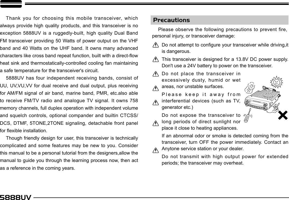
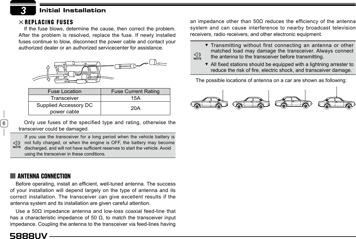
![73If you plan to use an external speaker, choose a speaker with an impedance of 8 Ω. The external speaker jack accepts a 3.5 mm (1/8") mono (2-conductor) plug.For voice communications, connect a microphone equipped with an 8-pin modular plug into the modular socket on the front of the main unit. Press rmly on the plug until the locking tab clicks. Attach the supplied microphone hanger in an appropriate location using the screws included in the screw set.To untilize the QPS5888UV software, you must first connect the transceiver to your PC then using an optional programming cable PC50 (via Data socket ).Please use QPS-5888UV software for programming. Initial InstallationEXTERNAL SPEAKERMICROPHONEPC CONNECTINGAsk your dealer about purchasing a Programming Cable PC51.ACCESSORIES CONNECTIONSSP-02http://www.qxdz.cnExternal speaker[SP-02]Microphone[QHM-04]Antenna[QCA-02]NOTEMicrophoneconnector](https://usermanual.wiki/Qixiang-Electron-Science-and-Technology/5888UV/User-Guide-1845118-Page-12.png)
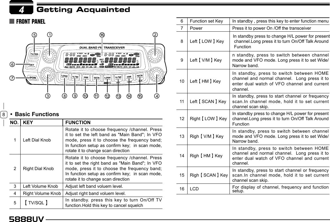
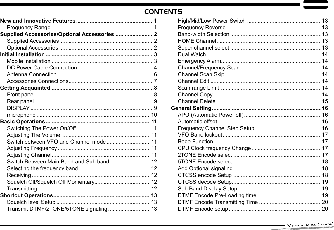
![11In standby, press correspondent key to switch between Frequency and channel mode, when the transceiver is in channel mode, the LCD will displays current channel.5Basic Operations POWER ONPress key to switch the transceiver ON, the LCD displays "WELCOME ANYTONE", then display current frequency or channel. POWER OFFPress key for over 0.5 Second to switch the transceiver OFF. Rotate the [VOLUME] knob of selected band clockwise to increase the volume, counterclockwise to decrease the volume.SWITCHING THE POWER ON/OFFADJUSTING THE VOLUME SWITCH BETWEEN VFO AND CHANNEL MODEADJUSTING FREQUENCYHold , keep press Monitor the background noise after the transceiver emits a DU beep, meanwhile adjust the [VOLUME] knob. During communication, volume can be adjusted more accurate.ADJUSTING FREQUENCY THROUGH SELECTOR KNOBINPUT FREQUENCY THROUGH MICROPHONE NUMBER KEYThe microphone [ UP/DOWN ] key also able to adjust frequency. Press [ UP/DOWN ] key will increase(decrease) the frequency by one step size. Hold [ UP/DOWN ] key will adjust the frequency continuously.When the Band lockout function is on, the input or adjusting of frequency band. The right band only limited in 136-174Mhz and 400-470Mhz.In frequency (VFO) mode, turn the selector knob clockwise to increase frequency; counterclock-wise to decrease frequency. Every gear will increase or decrease frequency by one step. To adjust the Main band frequency, press corre-spondent selector knob, the left side of decimal point will ash. In this status, turn the selector knob will increase or decrease frequency quickly by 1MHz stepIn VFO mode, you can input the frequency by the microphone numeric key. It is invalid to input frequency out of the frequency band.For example:to input 150.125Mhz, press 1, 5, 0, 1, 2, 5 continuously. to input 152 MHz, press1, 5, 2, continuously. ADJUSTING CHANNELADJUSTING CHANNEL THROUGH SELECTOR KNOBIn the channel mode, you can adjust the channel directly by the channel knob.Turn clockwise to increase one channel; turn counterclockwise to decrease one channel.To adjust the Main band channel, press POW5MinVolumeMaxVolumeNOTENOTENOTE](https://usermanual.wiki/Qixiang-Electron-Science-and-Technology/5888UV/User-Guide-1845118-Page-16.png)
![125888UVSWITCH BETWEEN MAIN BAND AND SUB BANDSELECTING THE FREQUENCY BANDIf there is any empty channel, the adjustment will ignore it and jump to next channel.This transceiver can be set working on 2 UHF band or 2 VHF band.INPUT CHANNEL THROUGH MICROPHONE NUMBER KEYIn channel mode, you can switch to desired channel by press 3 of the microphone numeric key (001-758). For example input 001 get channel 1; input 030 is channel 30; input 512 is channel 512. If the input channel is not programmed with frequency, the transceiver will emit a warning beep and return to last channel.This transceiver is default on dual receive, a "MAIN" icon will displays in the top right of the working frequency. The transmitting is only on the Main band. When the left Band is Main band, press the right selector knob will switch the right Band to Main band. Then press the left selector knob will switch the left Band to Main band.1. Choose for Left band: press the left side key to switch it to VFO mode, press the left selector knob over 1 second then repeater above operation will switch the left band .2. Choose for right band: press the right side key to switch it to VFO mode, press the right selector knob over 1 second then repeater above operation will switch the right band 5Basic OperationsRECEIVINGIf the transceiver has set at higher squelch level, it may fail to hear the calling. If the Busy and signal strength icon display inleft band or right band, but can not hear the calling, means the signal is with matching carrier but dis-matching signaling. In standby, both left band and right band able To receive. When they receive any signal, the BUSY icon and signal strength icon will appear in the correspondent area of the LCD. And you can hear the calling。SQUELCH OFF/SQUELCH OFF MOMENTARYLong press of key can be programmed as Squelch Off or Squelch Off Momentary to monitor the weak signal.1. Squelch Off: Hold key until hear "Du" beep, the squelch is off, repeat the above operation to resume squelch.2. Squelch Off Momentary: Keep hold key to disable squelch, Release the key to resume squelch.TRANSMITTINGHold PTT key, the transceiver change to transmitting. Please hold the mic-rophone approximately 2.5-5.0cm from your mouth, and then speak into the microphone in your normal voice to get best timbre.The transmitting only available on Main band, the TX icon will display in the top right corner of the Main band frequenIn standby, press the microphone to cancel squelch, press it again to turn on the squelch.correspondent selector knob, the channel number flashes in this situation, the channel number will increase 10 channels by each gear of selector knob. Press microphone [ UP/DOWN ] key also able to adjust the channel.5NOTENOTENOTENOTENOTE](https://usermanual.wiki/Qixiang-Electron-Science-and-Technology/5888UV/User-Guide-1845118-Page-17.png)
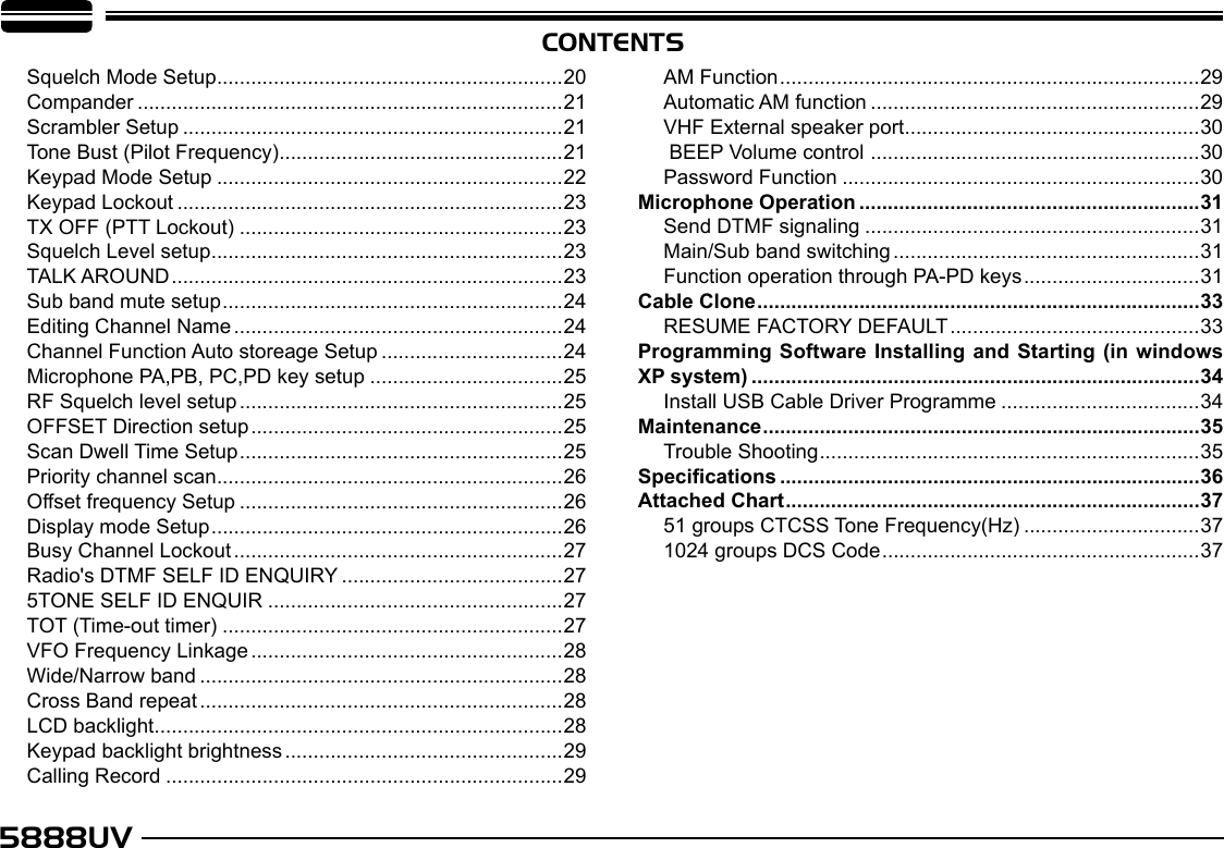
![13SQUELCH OFF/SQUELCH OFF MOMENTARY6Shortcut OperationsSQUELCH LEVEL SETUPhis function is used to setup the strength of receiving signal, when the stren gth reach a certain level, the calling can be heard, otherwise, the transceiver will keep mute. In standby, press and hold key, meanwhile switch the selector knob to adjust the squelch level of Main band. 1-20: Total 20 squelch levels available.OFF: turn off squelch. The background noise always on.The squelch level shall setup separately for right band and left band.TRANSMIT DTMF/2TONE/5TONE SIGNALINGIf the current channel is with DTMF/2TONE/5TONE signaling, hold PTT and [ UP ] key will transmit selected Pre-programmed signalingHIGH/MID/LOW POWER SWITCHIn standby, repeat press key to choose power levels as following:When LCD displays HIGH, the power on current channel is high.When LCD displays MID1, the power on current channel is middle 1When LCD displays MID2, the power on current channel is middle 2.When LCD displays LOW, the power on current channel is low.Output power for each level: HIGH MID1 MID2 LOWVHF(50W) VHF(20W) VHF(10W) VHF(5W)UHF(40W) UHF(20W) UHF(10W) UHF(5W)In channel mode, this operation is for temporary use onlyThis function is valid only when current channel setup with offset frequency and offset directionIn standby, press key to switch to HOME channel, and commnicatte on HOME channel. repeat press it to return to last channel.In standby, hold key for over 0.5second to turn On/ Off frequency reverse function. When reverse function is on, the TX frequency will change to RX frequency and RX frequency change to TX frequency. The signaling will also be reversed if CTCSS/DCS signaling existed in this channel.HOME CHANNELFREQUENCY REVERSE This transceiver has 1 band widthsIn standby, hold key for over 0.5 second to choose the 1 band widthsWhen LCD displays NARROW, current channel is work on narrow band 12.5KHzBAND-WIDTH SELECTION6NOTENOTENOTE SUPER CHANNEL SELECTIn standby, press the left or right volume knob will switch the radio work on super channel 1 or supper channel 2.](https://usermanual.wiki/Qixiang-Electron-Science-and-Technology/5888UV/User-Guide-1845118-Page-18.png)
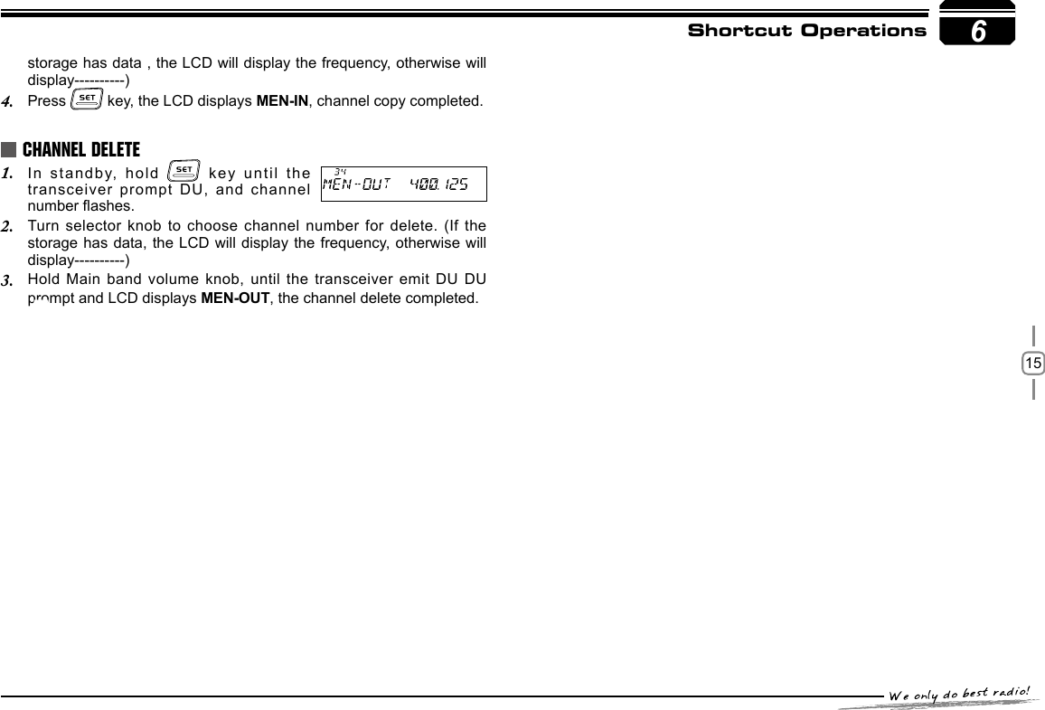
![145888UVShortcut Operations In standby, hold key for over 0.5 second to enter Dual Watch mode. The radio will scan the channel in every 5 seconds. When the radio receives match signal, it pause scanning until the signaling disappear. Repeat above operation to exit Dual watch.DUAL WATCHFREQUENCY SCANCHANNEL/FREQUENCY SCANIn VFO mode, this function is designed to monitor signal of every communicative frequency point of "step size" you have set. In VFO mode, press the Main Band 1. key to enter channel scan.During the scanning adjust the Main band selector knob or press 2. microphone [ UP/DOWN ] key will change the scan direction. Press 3. key to exit scan.CHANNEL SCANIn channel mode, press the Main Band 1. key to enter channel scan.During the scanning, adjust the Main band selector knob or press 2. microphone [ UP/DOWN ] key will change the scan direction.Press 3. key to exit scan.In channel mode, switch selector knob to choose the channel, then hold In VFO mode, turn selector knob to select the desired frequency or 1. input frequency by MIC's numeric keys.Hold 2. key until the transceiver prompt DU and the display of channel number ashes.Turn selector knob to select the channel number to store. (If the 3. storage has data , the LCD will display the frequency, otherwise will display----------)Press 4. key, the LCD display MEN- IN, the channel edit completed.In channel mode, turn the selector knob to choose the channel. 1. Hold 2. key until the transceiver prompt a Du and channel number display ashes.Turn selector knob to choose channel number for storage. ( If the 3. CHANNEL SCAN SKIPCHANNEL EDITCHANNEL COPY6EMERGENCY ALARMTo start emergency alarm, hold the right volume knob until the trans -ceiver displays ALARM and emit alarm. Re-power on the transceiver to exit alarm. This transceiver has 4 kind of alarm which can be setup by programming software.6 for over 0.5 second, the radio prompts "DU DU", and LCD displays "SKIP", and now the current channel is Scan Skip.SCAN RANGE LIMIT You can set the VFO scan frequency range by this function:Choose upper limit and lower limit frequency, there are L1/U1- L5/1. U5, five couple of limit frequency for selection. L stands for lower limit and U stands for the upper limit. the upper limit must over the lower limit frequency. Please refer the Channel Edit to setup the limit frequency.In VFO mode, set the VFO frequency in 2. the range between upper and lower limit.Press 3. key to start scan in lmited range.](https://usermanual.wiki/Qixiang-Electron-Science-and-Technology/5888UV/User-Guide-1845118-Page-19.png)
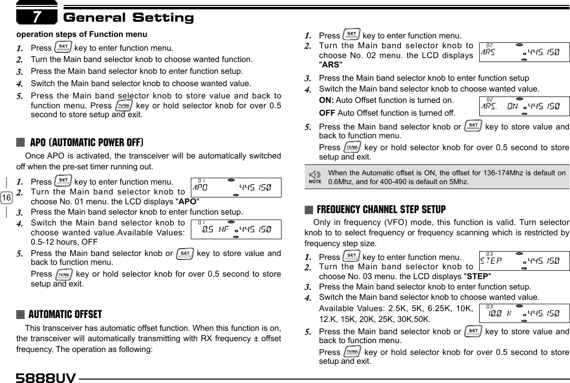
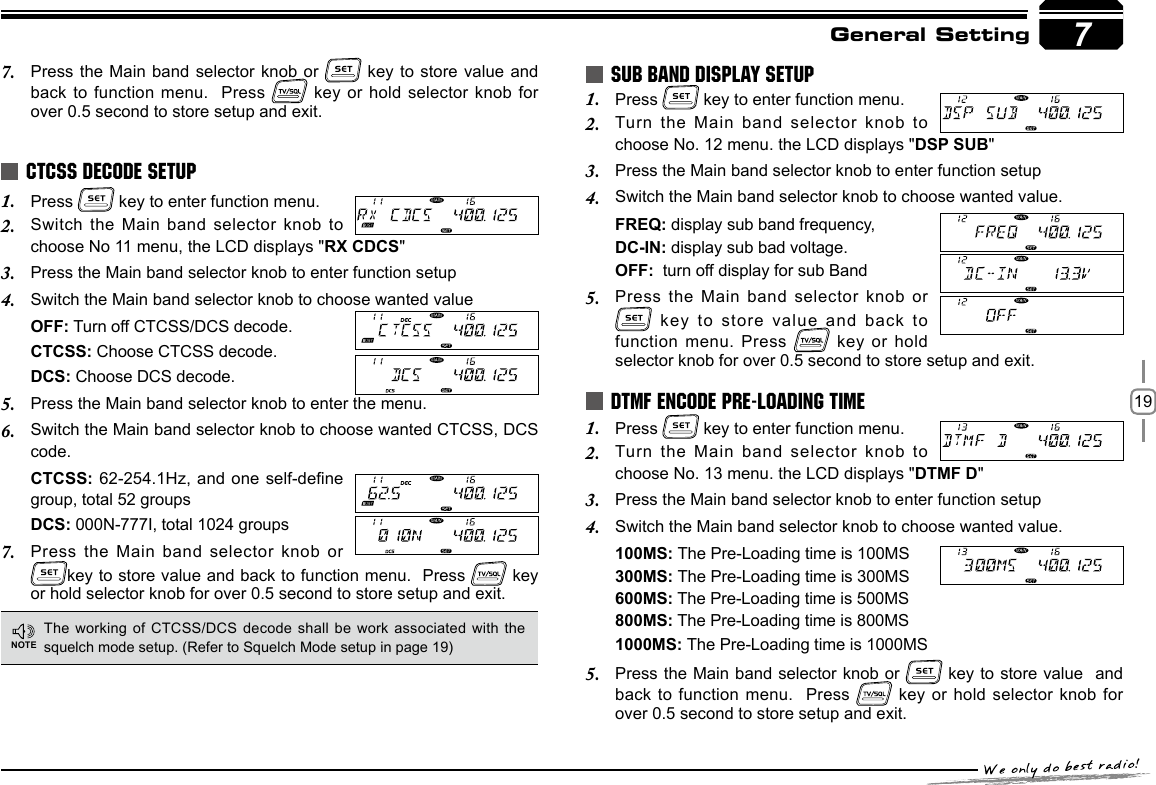
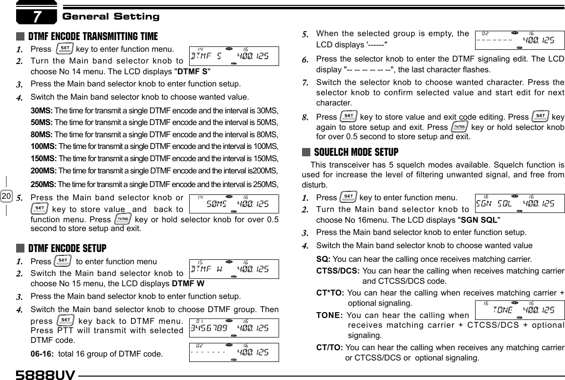
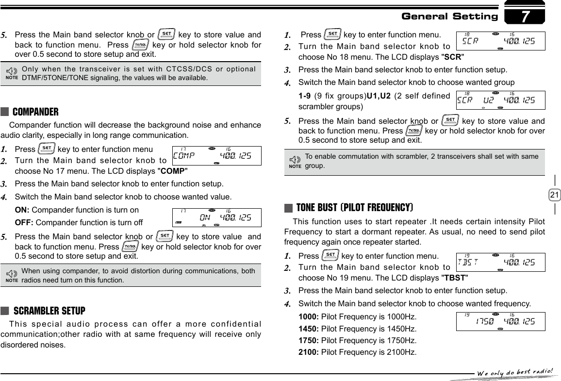
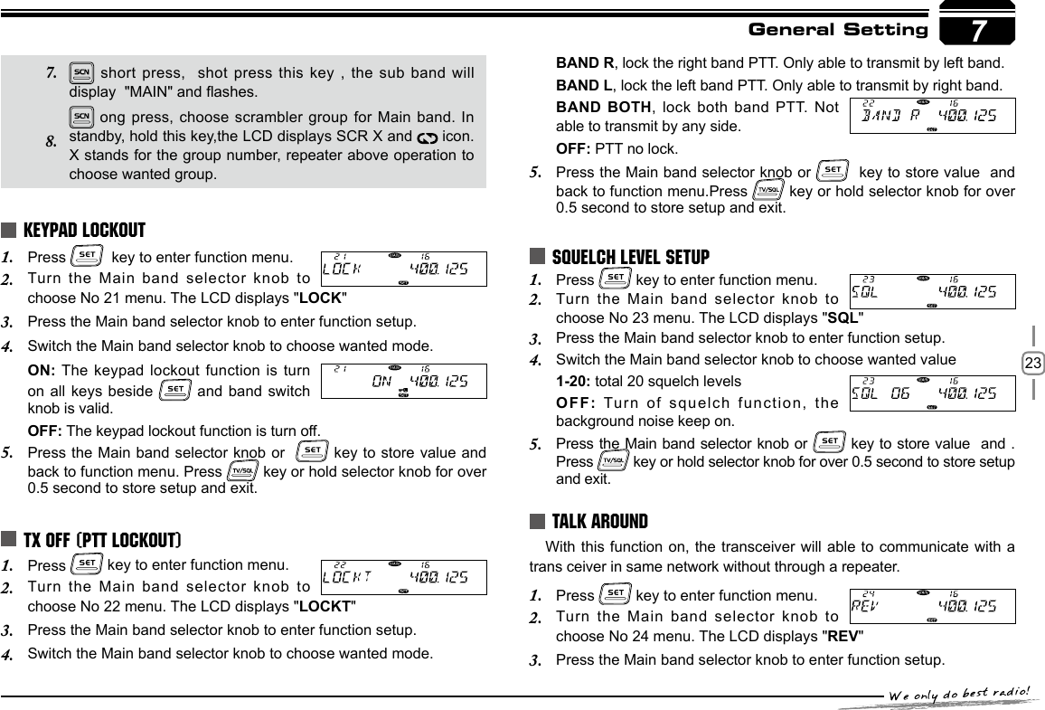
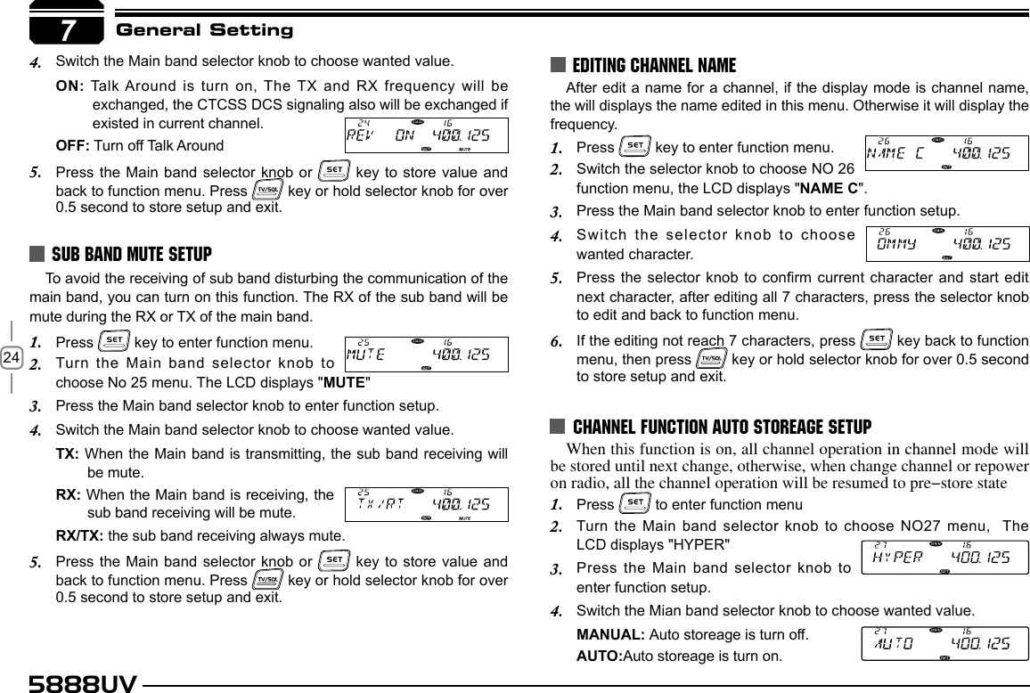
![225888UV7General SettingPress the Main band selector knob or 5. key to store value and back to function menu. Press key or hold selector knob for over 0.5 second to store setup and exit. Short press: In VFO mode, short press this key, the frequency step size changes to 1Mhz,in channel mode, adjust selector knob will jump 10 channels. long press: In standby, long press this key to ad/delete optional signaling, repeat the long press it, will set optional signaling DTMF,5TONE or 2TONE. When the LCD displays After the above setup, hold microphone PTT key and [ DOWN ] key, the radio will transmit selected tone.Press 1. key to enter function menu.Turn the Main band selector knob to 2. choose No 20 menu. The LCD displays "KEYMOD"Press the Main band selector knob to enter function setup.3. Switch the Main band selector knob to choose wanted mode.4. KEY1: key1 mode, Normal mode, the left 4 keys have same functions as the right 4 keys.KYE2: the left 4 keypads will shared by both band. And the right 4 key pads will re-dened.Press the Main band selector knob or 5. key to store value and back to function menu. Press key or hold selector knob for over 0.5 second to store setup and exit.KEYPAD MODE SETUPDT means DTMF, displays 5T means 5TONE, displays 2T means 2TONE. In VFO mode, long press this key, the step size change to 10Mhz. short press: Frequency reverse function, when current channel is setup with offset direction and offset frequency, press this key will turn on frequency reverse function. When frequency reverse function the TX frequency turns to RX frequency & RX frequency changes to TX frequency. The signaling will also be reversed if CTCSS/DCS signaling existed in this channel. Repeat shot press it will turn off Frequency reverse function. long press: In stand by, hold this key until the LCD displays , means the compander function is on, repeater above operation to turn off compander function. short press: In standby, press this key to set the CTCSS/DCS code for current channel.When the LCD displays ENC, the current channel is with CTCSS encode function.When the LCD displays ENC and DEC, the current channel is with CTCSS /DCS code function.When the LCD displays DCS and DCS icon, the current channel is with CTCSS code function.When the LCD displays OFF, the current channel is without CTCSS /DCS function. long press: In standby, long press this key to enter CTCSS/DCS scan, when nd matching CTCSS/DCS signal, the scan will pause in the way lowing Scan Dwell time.The scan direction can be changed by corresponding channel selector knob.Note:To enable this function, the channel shall be programmed with CTCSS/DCS decode.7NOTENotice: Denition of 4 Right band Keypad in KEY2 mode:3. 4. 5. 6. 1. 2.](https://usermanual.wiki/Qixiang-Electron-Science-and-Technology/5888UV/User-Guide-1845118-Page-27.png)
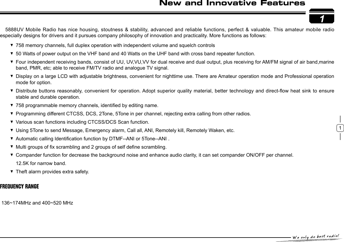
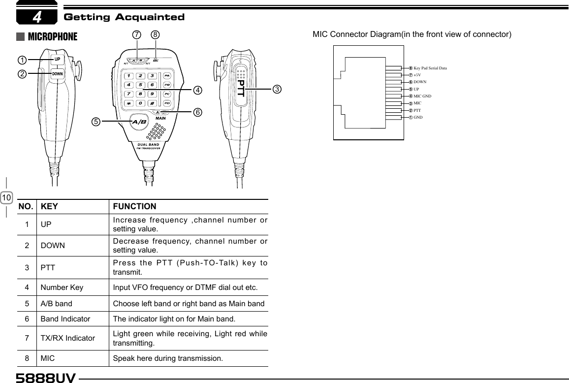
![318Microphone OperationSEND DTMF SIGNALINGMAIN/SUB BAND SWITCHINGFUNCTION OPERATION THROUGH PA-PD KEYSYou can operate the transceiver by keypad or input desired frequency and channel through the QHM-04 microphone.Hold the PTT key; input the desired DTMF signaling by the numeric keys.This transceiver is defaulted on dual receive, in this status, a MAIN icon will displayed in the top right corner of the Main band frequency,transmitting only available on the Main band. In standby, you can switch Main band and sub band by the A/B key.This function is valid only when current channel set with offset frequency.PRI:Add or delete priority channel: In channel mode, press the key programmed as PRI function to set priority channel, when the LCD displays the current channel is set as priority channel. repeat above operation, the disappear, the curent channel is not set as priority channel.LOW: Output power setup, in standby, press the key programmed as as LOW function will change the lower level.When LCD displays HIGH, the transmitting power on current channel is high. When LCD displays MID1, the transmitting power on current channel is middle1, When LCD displays MID2, the transmitting power on current channel is middle 2. When LCD displays LOW, the transmitting power on current channel is low.TONE: CTCSS/DCS code setup. In standby, press the key programmed as TONE function will able to setup CTCSS/DCS code.when the LCD key to choose CTCSS encode. When the LCD displays "ENC","DEC" and CTCSS frequency,press the microphone [ UP/DOWN ] key to choose CTCSS decode. When the LCD displays "DCS" and DCS code,press microphone displays "ENC" and CTCSS frequency, press the microphone [ UP/DOWN ] key to choose DCS code.MHZ: In VFO mode, press the key programmed as MHZ function, the megabit digital in the LCD flashes, now turn the channel know or microphone [ UP/DOWN ] key to adjust frequency by 1Mhz step. In channel mode, press this key, the channel number flashes, The PA,PB,PC,PD, keys are programmable, they can be endowed with the following functions.RPTR: OFFSET direction setup, in standby, press the key programmed as RPTR function will change the offset direction. when LCD displays"+", means plus offset, when the LCD displays"-", means minus offset.NOTEPTTMain/Sub band switchUPDOWNMICNumeric Keys](https://usermanual.wiki/Qixiang-Electron-Science-and-Technology/5888UV/User-Guide-1845118-Page-36.png)
![325888UV8Microphone Operationnow adjust selector knob or microphone [ UP/DOWN ] key to adjust channel.REV: In standby, press the key programmed as "REV" function to turnon or turn off Talk Around function.HOME: HOME channel switch, in standby press the key programmed as "HOME" function press the key programmed as HOME function to switch between HOME channel and current channel.MAIN: Main band switch, in standby press the key programmed as "MAIN" function to cho ose left band or right band as Main band.VFO/MR: Working mode switch. in standby, press the key programmed as "VFO/MR" function to switch between channel mode and frequency mode.SCAN: scan function in standby, press the key programmed as "SCAN" function to start channel scan or frequency scan.SQL OFF:Turn off Squelch, in standby, press the key programmed as "SQL OFF" function to turn off squelch, you can hear very weak signal, repeat the above function to turn on squelch.TBST: Transmit tone burst, in standby; press the key programmed as "TBST" function to transmit selected tone burst. This function is use to wake sleeping repeater.CALL OUT: Calling, in standby, press the key programmed as "CALL OUT" function to transmit pre-programmed DTMF, 2TONE, 5TONE code.COMP: Compander function in standby , press the key programmed as "COMP" to turn on or turn off Compander function.SCR: Scrambler function, in standby, press the key programmed as "SCR" function to turn on or turn off Scrambler function. And choose optional scrambler groups (from 9 xed groups and 2 self dened groups).TONE DEC: Add Optional Signaling, in standby press the key programmed as"TONE DEC" function to choose DTMF(DT), 2TONE(2T), 5TONE(5T)or OFF. W/N: Wide narrow band setup in standby, press the key programmed as "W/N" function to choose Wide band, middle and narrow band.OFF: No function.](https://usermanual.wiki/Qixiang-Electron-Science-and-Technology/5888UV/User-Guide-1845118-Page-37.png)