Qixiang Electron Science and Technology AT5888UVIII LAND MOBILE RADIO User Manual 15 5888UV III UserMan
Qixiang Electron Science& Technology Co., Ltd LAND MOBILE RADIO 15 5888UV III UserMan
UserManual.wiki
>
Qixiang Electron Science and Technology
>
AT5888UVIII User Manual
15_5888UV III UserMan.pdf
Navigation menu
Upload a User Manual
Namespaces
Wiki Guide
HTML
PDF
Info
Views
User Manual
Discussion / Help
Navigation

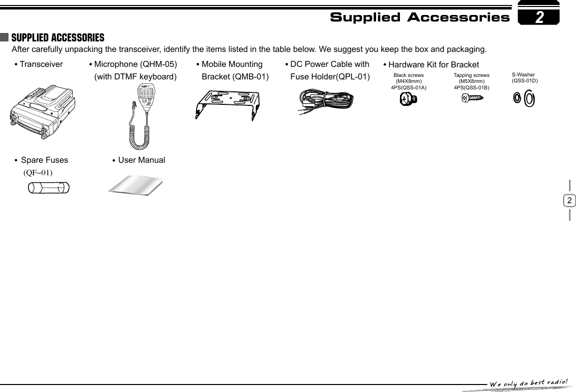
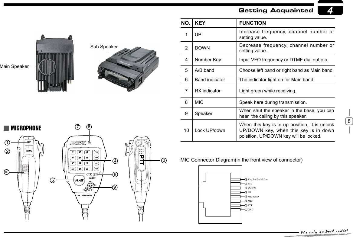
![73If you plan to use an external speaker, choose a speaker with an impedance of 8Ω. The external speaker jack accepts a 3.5mm (1/8") mono (2-conductor) plug.For voice communications, connect a microphone equipped with an 8-pin modular plug into the modular socket on the front of the main unit. Press rmly on the plug until the locking tab clicks. Attach the supplied microphone hanger in an appropriate location using the screws included in the screw set.Initial InstallationEXTERNAL SPEAKERMICROPHONEACCESSORIES CONNECTIONSExternal speaker[SP-02]Microphone[QHM-04]Antenna[QCA-02]MicrophoneconnectorSP-02](https://usermanual.wiki/Qixiang-Electron-Science-and-Technology/AT5888UVIII/User-Guide-2982421-Page-12.png)
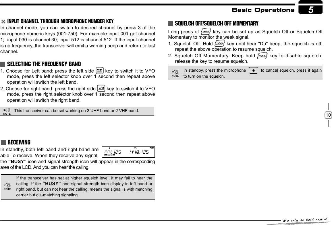
![9In frequency (VFO) mode, turn the selector knob clockwise to increase frequency; counterclock-wise to decrease frequency. Every gear will increase or decrease frequency by one step. To adjust the Main band frequency, press corresponding selector knob, the left side of decimal point will flash. In this status, turn the selector knob will increase or decrease frequency quickly by 1MHz step.ADJUSTING FREQUENCY THROUGH SELECTOR KNOBINPUT FREQUENCY THROUGH MICROPHONE NUMBER KEY5Basic Operations POWER ONPress key to switch the transceiver ON, the LCD displays "WELCOME ANYTONE", then display current frequency or channel. POWER OFFPress key for over 0.5 Second to switch the transceiver OFF. Rotate the [VOLUME] knob of selected band clockwise to increase the volume, counterclockwise to decrease the volume.SWITCHING THE POWER ON/OFFADJUSTING THE VOLUME ADJUSTING FREQUENCYHold ,keep pressing it to Monitor the background noise after the transceiver emits a DU beep, meanwhile adjust the [VOLUME] knob. During communication, volume can be adjusted more accurate.The microphone [ UP/DOWN ] key also able to adjust frequency. Press [ UP/DOWN ] key will increase(decrease) the frequency by one step size. Hold [ UP/DOWN ] key will adjust the frequency continuously.When the Band lockout function is on, the input or adjusting of frequency bandwill limit within the current VFO band. Decrease frequency Increase frequencyIn VFO mode, you can input the frequency by the microphone numeric key. It is invalid to input frequency out of the frequency band.For example:to input 150.125Mhz, press 1, 5, 0, 1, 2, 5 continuously. to input 152 MHz, press1, 5, 2, continuously. ADJUSTING CHANNELADJUSTING CHANNEL THROUGH SELECTOR KNOBIn channel mode, you can adjust the channel directly by the channel knob. Turn clockwise to increase one channel; turn counterclockwise to decrease one channel. To adjust the Main band channel, press PowerMinVolumeMaxVolumeNOTENOTENOTEIf there is any empty channel, the adjustment will ignore it and jump to next channel.correspondent selector knob, the channel number ashes in this situation, the channel number will increase 10 channels by each gear of selector knob. Press microphone [ UP/DOWN ] key also able to adjust the channel.NOTE](https://usermanual.wiki/Qixiang-Electron-Science-and-Technology/AT5888UVIII/User-Guide-2982421-Page-14.png)
![116Shortcut OperationsSQUELCH LEVEL SETUPThis function is used to setup the strength of receiving signal, when the strength reach a certain level, the calling can be heard, otherwise, the transceiver will keep mute. In standby, press and hold key, meanwhile switch the selector knob to adjust the squelch level of Main band. 1-20: Total 20 squelch levels available.OFF: turn off squelch. The background noise always on.The squelch level shall setup separately for right band and left band.In standby, press key to switch to HOME channel, and communicate on HOME channel. repeat pressing it to return to last channel.HOME CHANNELNOTE HYPER MEMORY CHANNELIn standby, press the left or right volume knob will switch the radio work on hyper channel 1 or hyper channel 2.In standby, hold key for over 0.5 second to enter Dual Watch mode. The radio will scan the channel in every 5 seconds. When the radio receives matching signal, it pause scanning until the signaling disappear. Repeat above operation to exit Dual watch.DUAL WATCHFREQUENCY SCANCHANNEL/FREQUENCY SCANIn VFO mode, this function is designed to monitor signal of every communicative frequency point of "step size" you have set. In VFO mode, press the Main Band 1. key to enter channel scan.During the scanning adjust the Main band selector knob or press 2. microphone [ UP/DOWN ] key will change the scan direction.Press 3. key to exit scan.CHANNEL SCANIn channel mode, press the Main Band 1. key to enter channel scan.EMERGENCY ALARMTo start emergency alarm, hold the right volume knob until the trans -ceiver displays ALARM and emit alarm. Re-power on the transceiver to exit alarm. This transceiver has 4 kind of alarm.In VFO mode, after setting desired freq and Channel, press then hold until radio announces"DUDU", LCD displays H icon, Home channel editing nished.EDITING HOME CHANNEL](https://usermanual.wiki/Qixiang-Electron-Science-and-Technology/AT5888UVIII/User-Guide-2982421-Page-16.png)
![12Shortcut OperationsIn channel mode, switch selector knob to choose the channel, then hold for over 0.5 second, the radio prompts "DU DU", and LCD displays "SKIP", and now the current channel is Scan Skip.In VFO mode, turn selector knob to select the desired frequency or 1. input frequency by MIC's numeric keys.Hold 2. key until the transceiver prompt DU and the display of channel number ashes.Turn selector knob to select the channel number to store. (If the 3. storage has data, the LCD will display the frequency, otherwise will display"----------")Hold 4. key, the LCD display MEN- IN, the channel edit completed.CHANNEL SCAN SKIPCHANNEL EDIT6SCAN RANGE LIMIT You can set the VFO scan frequency range by this function:Choose upper limit and lower limit frequency, there are L1/U1- L5/1. U5, five couple of limit frequency for selection. L stands for lower limit and U stands for the upper limit. the upper limit must over the lower limit frequency. Please refer to the Channel Edit to setup the limit frequency.In VFO mode, set the VFO frequency in 2. the range between upper and lower limit.Press 3. key to start scan in lmited range.During the scanning, adjust the Main band selector knob or press 2. microphone [ UP/DOWN ] key will change the scan direction.Press 3. key to exit scan.In standby, hold 1. key until the transceiver prompt DU, and channel number ashes.Turn selector knob to choose channel number for delete. (If the 2. storage has data, the LCD will display the frequency, otherwise will display "----------")Hold 3. Left band volume knob, until the transceiver emit DU DU prompt and LCD displays MEN-OUT, the channel delete completed.CHANNEL DELETEstorage has data, the LCD will display the frequency, otherwise will display "----------")Hold4. key, the LCD displays MEN-IN, channel copy completed.In channel mode, turn1. the selector knob to choose the channel. Hold 2. key until the transceiver prompt a Du and channel number display ashes.Turn selector knob to choose channel number for storage. ( If the 3. CHANNEL COPY](https://usermanual.wiki/Qixiang-Electron-Science-and-Technology/AT5888UVIII/User-Guide-2982421-Page-17.png)
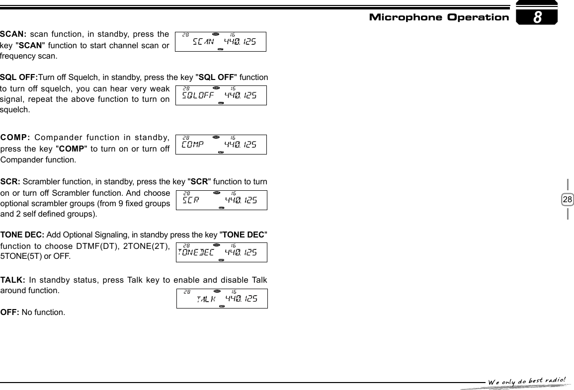
![278Microphone OperationFUNCTION OPERATION THROUGH PA-PD KEYSYou can operate the transceiver by keypad or input desired frequency and channel through the QHM-05 microphone.This function is valid only when current channel set with offset frequency.PRI:Add or delete priority channel: In channel mode, press the key PRI function to set priority channel, when the LCD displays the current channel is set as priority channel. Repeat above operation, the disappear, the curent channel is not set as priority channel.The PA, PB, PC, PD, keys can be set up with the following functions.RPTR: OFFSET direction setup, in standby, press the key RPTR function will change the offset direction. When LCD displays"+", means plus offset, when the LCD displays"-", means minus offset.NOTEMain/Sub band switchUPDOWNMICNumeric KeysUP/DOWN lock keyMicrophone speakerREV: In standby, press the key "REV" function to turn-on or turn off Frequency Revrse function.HOME: HOME channel switch, in standby press the key "HOME" function to switch between HOME channel and current channel.MAIN: Main band switch, in standby press the key "MAIN" function to choose left band or right band as Main band.VFO/MR: Working mode switch, in standby, press the key "VFO/MR" function to switch between channel mode and frequency mode.TONE: CTCSS/DCS code setup. In standby, press the key TONE function will be able to setup CTCSS/DCS code. When the LCD displays "ENC" and CTCSS frequency, press the [ UP/DOWN ] key to choose CTCSS encode. When the LCD displays "ENC", "DEC" and CTCSS frequency, press the microphone [ UP/DOWN ] key to choose CTCSS decode. When the LCD displays "DCS" and DCS code, press the microphone [ UP/DOWN ] key to choose DCS code.MHZ: In VFO mode, press the key MHZ function, the megabit digital in the LCD ashes, now turn the channel knob or microphone [ UP/DOWN ] key to adjust frequency by 1Mhz step. In channel mode, press this key, the channel number flashes, now adjust selector knob or microphone [ UP/DOWN ] key to adjust channel.](https://usermanual.wiki/Qixiang-Electron-Science-and-Technology/AT5888UVIII/User-Guide-2982421-Page-32.png)