Qixiang Electron Science and Technology AT778UV Mobile Radio User Manual
Qixiang Electron Science& Technology Co., Ltd Mobile Radio
UserManual.wiki
>
Qixiang Electron Science and Technology
>
AT778UV User Manual
>
User Manual
Contents
1.
User Manual
2.
User Manual based on Occupational Limits
3.
User manual
4.
Safety Usage Training Document
User Manual
Navigation menu
Upload a User Manual
Namespaces
Wiki Guide
HTML
PDF
Info
Views
User Manual
Discussion / Help
Navigation
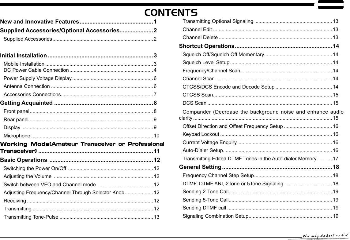
![73SP-01SP-01 GroundMicrophone connectorMicrophone [QHM-03] Antenna [QCA-01]External speaker [SP-01]Errorhttp://www.qxdz.cnInitial Installation External Speaker MicrophonePC ConnectingIf you plan to use an external speaker, choose a speaker with an impedance of 8Ω. The external speaker jack accepts a 3.5mm (1/8")mono (2-conductor) plug.For voice communications, connect a microphone equipped with an 8-pin modular plug into the modular socket on the front of the main unit. Press rmly on the plug until the locking tab clicks. Attach the supplied microphone hanger in an appropriate location using the screws included in the screw set.To utilize the optional QPS-778 software, you must rst connect the transceiver to your PC then using an optional programming cable PC50 (via Data socket ).Please use QPS-778 software for programming.External speaker adopt double port BTL, please care about the connecting way. The speaker can not connect with the ground, otherwise the speaker will be fault. The wrong connecting way as the following picture.Accessories Connections145.0000](https://usermanual.wiki/Qixiang-Electron-Science-and-Technology/AT778UV.User-Manual/User-Guide-2487677-Page-12.png)
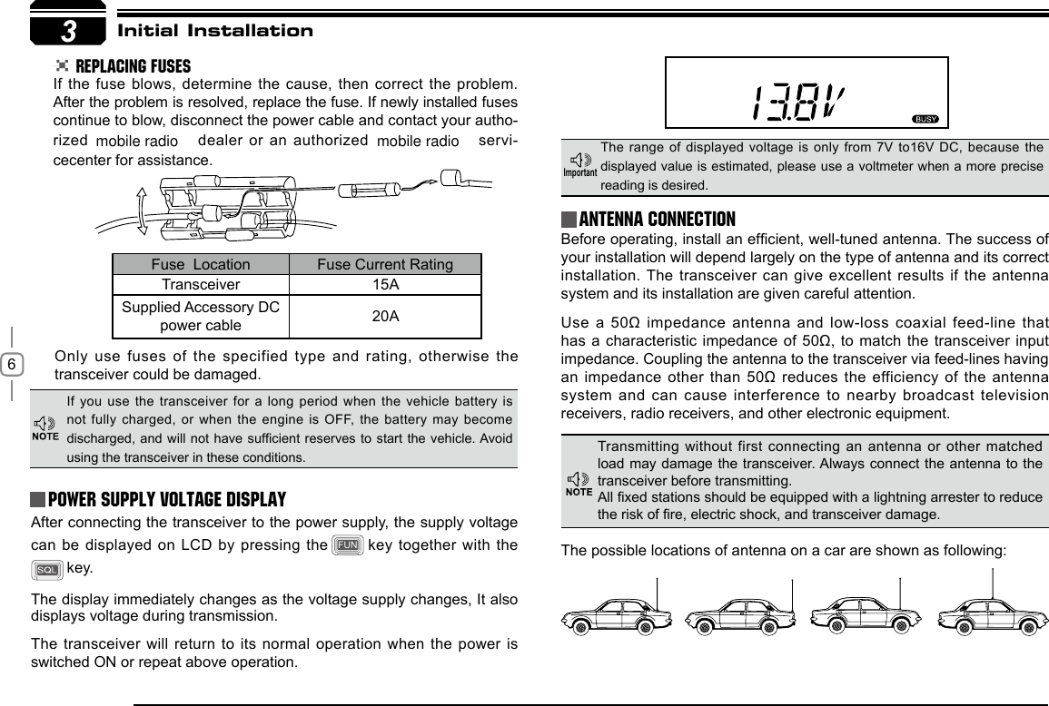
![12In standby, press key or Microphone's key until appear , this indicates current channel in channel mode. Repeat above 6Basic Operations Switching The Power On/OffAdjusting The Volume Switch between VFO and Channel modeAdjusting Frequency/Channel THROUGH SELECTOR KNOBReceivingAccording to the option selected during installation Press the switch or turn the ignition key to ACC (speed up) or ON (startup) position to power on radio. Press the key for 1s or turn the ignition key to OFF position to turn off.When the channel you are operating is called, the screen shows and field intensity, in this way, you can hear the calling from transmitting party.Under frequency (VFO) mode, you can 1. change the current frequency to the desired one through selector knob; Turn clockwise to increase frequency; turn counterclockwise to decrease. Every gear will increase or decrease one step. Press key, the decimal point of Turn the VOL knob clockwise to increase the audio level, counterclockwise to decrease. During communication, volume can be adjusted more accurate.If the transceiver has set at higher squelch level, it may fail to hear the calling.operation to switch between Frequency mode (VFO) and Channel mode.frequency in screen will be auto-hidden. In this status, turn selector knob or Microphone [ / ] key will increase or decrease frequency quickly by 1MHz step.Under channel mode, you can change the current channel to the 2. desired one through selector knob, clockwise turn to the forward channel, anticlockwise turn to the backward channel. In relative working mode, Microphone's [ / ] key has same function for adjusting frequency and channel.TransmittingPress and hold key or press MIC's key to monitor for a while to conrm the channel desired is not busy. Release or press Mic's key to return standby status, then press and hold [PTT] key to speak into microphone.When the channel you are operating is called, the screen shows BUSY and field intensity, you can't hear the calling from transmitting party, it means current channel receives a matching carrier but unmatching signaling(Refer to CTCSS/DCS encode and decode or Optional Signaling setup).](https://usermanual.wiki/Qixiang-Electron-Science-and-Technology/AT778UV.User-Manual/User-Guide-2487677-Page-17.png)
![13Basic Operations Transmitting Tone-PulseTransmitting OPTIONAL SIGNALING Press and hold [PTT] key, then press Microphone [ ] key to transmit current selected tone-pulse signal. Press and hold [PTT] key, then press Microphone key or press key in front panel or press Mic's key to transmit pre-stored and selected DTMF/2Tone/5Tone optional signaling.Channel EditChannel DeleteUnder frequency mode (VFO), turn 1. selector knob to select the desired frequency or input frequency by MIC's numeric keys.Press2. key to enter CTCSS/DCS signaling setup, turn selector knob to select the desired signaling.Press3. key, LCD appears , icon and current channel number, icon ashing means current channel is Under channel mode, turn selector knob to select channel which 1. you want to delete.Press2. key and key together, current channel will be deleted and emitted a prompt voice. icon ashing means current channel is deleted.empty.Turn selector knob to select the desired channel number to store.4. Press 5. key, , icon and channel number disappears and emit a prompt voice, thus the channel storage succeed.6Please hold the microphone approximately 2.5-5.0cm from your lips , and then speak into the microphone in your normal speaking voice to get best timbre.Press and hold [PTT] key, LED lights RED and power intensity showed in screen indicates it is transmitting, release to receive.](https://usermanual.wiki/Qixiang-Electron-Science-and-Technology/AT778UV.User-Manual/User-Guide-2487677-Page-18.png)
![147Shortcut OperationsSquelch level SetupFrequency/Channel ScanChannel ScanCTCSS/DCS Encode and Decode setupSetting the radio to a tight squelch level, you can avoid unwanted signals or noise, but you may not receive a weak signal. Therefore, it will be better for you to select the normal squelch level.In frequency (VFO) mode, this function is designed to monitor signal of every communicative frequency point of transceiver "step size" you have set. In channel mode, this function is designed to monitor signal in every channel. In channel mode, Press 1. key for 1s to enter into channel scan. Repeatedly press key to check whether set CTCSS/DCS encode and decode in current channel or not.While standby, press 1. key and turn selector knob until LCD appears and current squelch level.Turn selector knob or press MIC [ 2. / ] key to set desired squelch level.Press any key except 3. and key to exit. Frequency ScanIn VFO mode, press 1. for 1s to enter into frequency scan.Turn selector knob or press Microphone 2. [ / ] key to change scan direction.Press any key except 3. and key to exit.Turn selector knob or press Microphone 2. [ / ] key to change scan direction.Press any key except3. and key to exit. squelch off/squelch off momeNTARY key programmed as Squelch Off or Squelch Off Momentary to monitor the weak signal.Squelch Off: Press1. key to disable squelch, press key again to resume squelch.Squelch Off Momentary: Press and hold2. key to disable squelch, release key to resume squelch.The above functions should be set in programme software.When LCD appears 1. icon, it means current channel with CTCSS encode, turn selector knob or press Microphone's [ / ] key to select desired CTCSS encode.When LCD appears2. and icon, it means current channel with CTCSS encode and decode, turn selector knob or press Microphone's [ / ] to select desired CTCSS code.](https://usermanual.wiki/Qixiang-Electron-Science-and-Technology/AT778UV.User-Manual/User-Guide-2487677-Page-19.png)
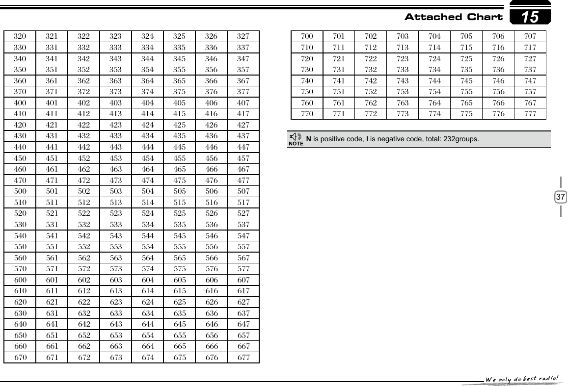
![157Shortcut OperationsCTCSS SCANRepeatedly press key until LCD displays and icons, then hold key for 1S to enter into CTCSS scanning. Once nding a matching CTCSS signaling, it will stop for 15s then scan again.Under channel mode, this operation can be temporarily used by user. Once the radio is turned off or switched to another channel, the temporary setting will be erased.When LCD appears 3. icon, it means current channe can be set with DCS encode and decode together, turn selector knob or press Microphone's [ / ] to select desired DCS encode and decode.CTCSS:62.5-254.1, Total 51groups; DCS:000N-777I total 1024 4. groups. N is positive code, I is inverse code.Press any key except 5. , and keys to return into standby status. Repeatedly press key until LCD displays DCS icons, then hold key for 1S to enter into DCS scanning. Once nding a matching DCS signaling, it will stop for 15s then scan again.Compander function will decrease the background noise and enhance audio clarity, especially in long range communication.Press 1. key, then press key to turn on compander function, repeat above operation again to turn off compander function.Compander (Decrease the background noise and ENHANCE AUDIO CLARITY)When LCD appears 2. icon, enable compander in current channel.When LCD doesn't display 3. icon, disable compander in current channel.DCS SCAN](https://usermanual.wiki/Qixiang-Electron-Science-and-Technology/AT778UV.User-Manual/User-Guide-2487677-Page-20.png)
![16Press 1. key until LCD displays icon, then press key until, LCD displays icon, it indicates keypad lockout function is valid.Repeat above operation, 2. icon disappears, it indicates keypad lockout function is invalid.This will automatically transmit pre-programmed and stored DTMF tones. And they are often used to remote control electronic devices or AUTOPATCH phone systems available on some repeater.Press and hold 1. key, then press key to enter the auto-dialer enquiry mode, LCD displays current default data and current group displayed on left. If no data in current group, it shows "EMPTY".Press and hold 1. key, then press key, LCD displays current battery voltage.Repeat above operation to return into 2. VFO or Channel mode.When LCD displays " " icon, it indicates negative offset, which 4. means transmitting frequency lower than receiving frequency.Turn selector knob or Mic's [ 5. / ] key to change offset frequency, offset frequency changed as per stepping.Press any key except 6. and key to exit into standby.Press 1. key until the icon displays on the LCD, then press key, LCD displays offset direction and offset frequency.Repeatedly press 2. key to select positive offset and negative offset.When LCD displays " " icon, it indicates 3. positive offset, which means transmitting frequency higher than receiving frequency.7Avoiding unintentional operation, this function will lock main keys, all keys except , and key are invalid.KEYPAD LOCKOUTCurrent Voltage ENQUIRYAuto-Dialer SetupShortcut OperationsThis function will display Current Battery Voltage.Under channel mode, this operation can be temporarily used by user. Once the radio is turned off or switched to another channel, the temporary setting will be erased.In voltage display mode, all functions and channel or frequency selection are invalid.Repeater receives a signal(UP-LINK) on one frequency and re-transmits on another frequency(DOWN-LINK). The difference between these two frequencies is called the offset frequency. If the UP-LINK frequency higher than DOWN-LINK frequency, the direction is positive, If it is lower, the shift direction is negative.Offset Direction and offset frequency setup](https://usermanual.wiki/Qixiang-Electron-Science-and-Technology/AT778UV.User-Manual/User-Guide-2487677-Page-21.png)
![18 Press and hold 1. key for over 2s to enter general setting menu.Press 2. / key to choose No.01 menu, LCD displays "STP--125".Turn selector knob to select the desired 3. frequency channel step. Channel step: 5K, 6.25K, 8.33K, 10K, Press 4. key to conrm and exit.Press and hold1. key for over 2s to enter general setting menu.Press 2. or to select the desired function option.Turn selector knob to select the desired setup.3. Press4. to conrm and exit.Meanwhile, if you want to edit channel name or start up menu, press or to move forward or backward, Press to store and exit.Only in frequency (VFO) mode, this function is valid. Turn selector knob to select frequency or frequency scanning which is restricted by frequency step size. 8General SettingFrequency Channel Step SetupThis function is auto-hidden in channel mode. DTMF, DTMF ANI, 2Tone or 5Tone SignalingDTMF/5Tone/2Tone signalling function as similarily as CTCSS/DCS. Without receiving correspondent tone signalling, the speaker will remain mute. DTMF and 5Tone signalling can be applied for other advanced features such as ANI, PTT ID, group call, remotely stun, remotely kill, waken,...etc.. The signalling edition must be done through programming software. Please refer to the HELP option in the programming software to know how to operate these features.Press and hold 1. key for over 2s to enter into general setting menu.Press 2. / to choose No.2 menu, LCD displays "T-OFF".Turn selector knob to 3. select the desired setup." DTMF": The channel will be mute by a DTMF signal. The speaker won’t be open until receiving a correspondent DTMF signal. Hold "PTT" then press [UP] or press directly to transmit the pre-stored DTMF signaling. In Profession transceiver mode, the functions from No.1 to No.17 will be auto-hidden.In DTMF signaling mode,press for 2s until LCD displays "AN---", turn selector knob to select desired digit (the other party ID).In this mode, press to confirm exist digit and move cursor to next, press to forward cursor.After editing, press key to operate ANI call." 2TONE": The channel will be mute by a 2-Tone signal. The speaker won ’t be open un til receivi ng a correspondent 2-Tone signal. Hold "PTT" then press [UP] or press directly to transmit the pre-stored 2-Tone signaling." 5Tone": The channel will be mute by a 5-Tone signal. The Speaker won’t be open until receiving a correspondent 5-Tone signal. Hold "PTT" then press [UP] or 12.5K,](https://usermanual.wiki/Qixiang-Electron-Science-and-Technology/AT778UV.User-Manual/User-Guide-2487677-Page-23.png)
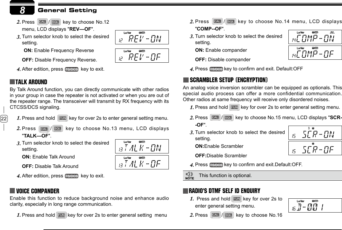
![218TX OFF SETUPDisable this function, it is invalid to press PTT, current channel only works in RX mode.Press and hold 1. key for over 2s to enter general setting menu.Press 2. / key to choose No.09 menu, LCD displays "TX-ON".Turn selector knob to select the desired 3. setting.ON: In current channel, Press PTT to transmit. OFF: In current channel, Press PTT is invalid.Press 4. key to conrm and exit. Default:ON.Busy Channel LockoutBCLO is to disable transmitting while RX signal is received. Once the channel is busy and you press PTT, the radio will beep as warning and get back to receiving.Press and hold 1. key for over 2s to enter general setting menu.Press 2. / key to choose No.10 menu, LCD displays "LOCK--OFF".Turn selector knob to select the desired setting.3. BU: Enable BCLO, Carrier lockout, transmitting is inhibited when current channel receives a matching carrier; press [PTT] to emit error voice prompt and back to receiving status.RL: Enable BTLO, transmitting is inhibited when current channel receives a matching carrier but dis-matching CTCSS/DCS. Press [PTT] to emit error voice prompt and back to receiving status.OFF: Busy channel lockout is disabled.It can transmit in any receiving status.Press 4. key to conrm and exit.Press and hold 1. key for over 2s to enter general setting menu.Press 2. / key to choose No.11 menu, LCD displays cursor and ashing.Turn selector knob to select the desired letter, press 3. key to conrm selected letter and enter into next edition, Press to return forward edition.After edition, press 4. key to exit.Reverse TX/RXGeneral SettingEditing Channel NAME In Frequency (VFO) mode, this function will be auto-hidden.TX frequency turns to RX frequency & RX frequency changes to TX frequency. The signaling will also be reversed if CTCSS/DCS signaling exited in this channel.Press and hold 1. key for over 2s to enter general setting menu](https://usermanual.wiki/Qixiang-Electron-Science-and-Technology/AT778UV.User-Manual/User-Guide-2487677-Page-26.png)
![279You can operate the transceiver by keypad or input desired frequency or channel through the QHM-03 microphone (Note:In professional transceiver mode, other keys are invalid except PTT, [ / ], and ).Keypad LockPull down the slide switch to lock position, the lamp is turned off and all of keypads is not work except PTT switch.Transmitting DTMF By Microphone KeyPAD Switches between VFO and channel mode In standby, press key to switch between channel mode and Frequency mode (VFO).Short CallingIn standby, press to transmit the selected DTMF/2TONE/5TONE in current channel.Transmitting DTMF Code:In standby, press , LCD displays DTMF data and group. Press [ / ] key to select the desired transmitting DTMF group, then Press PTT to transmit.If no DTMF data in current group, LCD displays "EMPTY", press key again and input desired DTMF code by keypad, press PTT to transmit and store DTMF data.Squelch LevelIn standby, press 1. , then press , LCD displays "SQL" and current squelch level.Press 2. / to adjust the desired squelch level. (press , then press , turn selector knob also can adjust the desired squelch level.Press number key to conrm and exit.3. Optional signaling In standby, press , then press to add optional signaling, repeat above operation to set DTMF, 2TONE or 5TONE signaling.When rst bit of Exa byte in frequency displays "D", it in dic ate s D TMF function enable. When rst bit of Exa byte in frequency displays "T", it indicates 2Tone function enable. Microphone OperationSlide DTMF key to DTMF position, press and hold the [PTT] key, transmitting the desired DTMF signaling by the numeric key directly.(Note:Slide DTMF key to DTMF position, the keyboard is invalid in standby).Function Setup By Microphone KeypadSquelch off:In standby, press key, the squelch is disabled when icon ashed in LCD, Press again to enable squelch and the icon disappears.](https://usermanual.wiki/Qixiang-Electron-Science-and-Technology/AT778UV.User-Manual/User-Guide-2487677-Page-32.png)
![289Reverse TX/RXTX frequency turns to RX frequency & RX frequency changes to TX frequency. The signaling will also be reversed if CTCSS/DCS signaling exited in this channel.In standby, press 1. , then press , LCD displays "REV—ON".Press [ 2. / ] to select the desired value.ON:Enable Frequency ReverseOFF:Disable Frequency ReversePress number keys to conrm and exit.3. In corresponding mode, press then press key to enter into scanning. In scanning mode, press / to change scan direction.Busy Channel LockoutBCLO is to disable transmitting while RX signal is received. Once the channel is busy and you press PTT, the radio will beep as warning and get back to receiving.In standby, press 1. , then press to enter into Busy Channel Lockout.Press [ 2. / ] to select the desired value.BU: Enable BCLO, Carrier lockout, transmitting is inhibited when current channel receives a matching carrier; press [PTT] to emit error voice prompt.RL: Enable BTLO, transmitting is inhibited when current channel receives a matching carrier but dis-matching CTCSS/DCS. Press [PTT] to emit error voice prompt It can transmit in any receiving status.OFF: Busy channel lockout is disabled.Press number keys to conrm and exit.3. This function can be temporarily used in channel mode. Once the radio is turned off or switched to another channel, the temporary setting will be erased and back to initial settings. Frequency/Channel scan Scan Skip When rst bit of Exa byte in frequency displays "F", it indicates 5Tone function enable.This function can be temporarily used in Channel mode. Once the radio is turned off or switched to another channel, the temporary setting will be erased and back to initial settings. This function can be temporarily used in Channel mode. Once the radio is turned off or switched to another channel, the temporary setting will be erased and back to initial settings. Microphone OperationIn Channel mode, press then press , decimal point displayed between frequency's ten digit and unit digit, it means current channel is scan skip. Repeat above operation to set scan or scan skip in current channel.decimal point displayed between frequency's ten digit and unit digit, 1. it means current channel is scanned skip.decimal point is not displayed between frequency's ten digit and 2. unit digit, it means current channel is scanned.](https://usermanual.wiki/Qixiang-Electron-Science-and-Technology/AT778UV.User-Manual/User-Guide-2487677-Page-33.png)
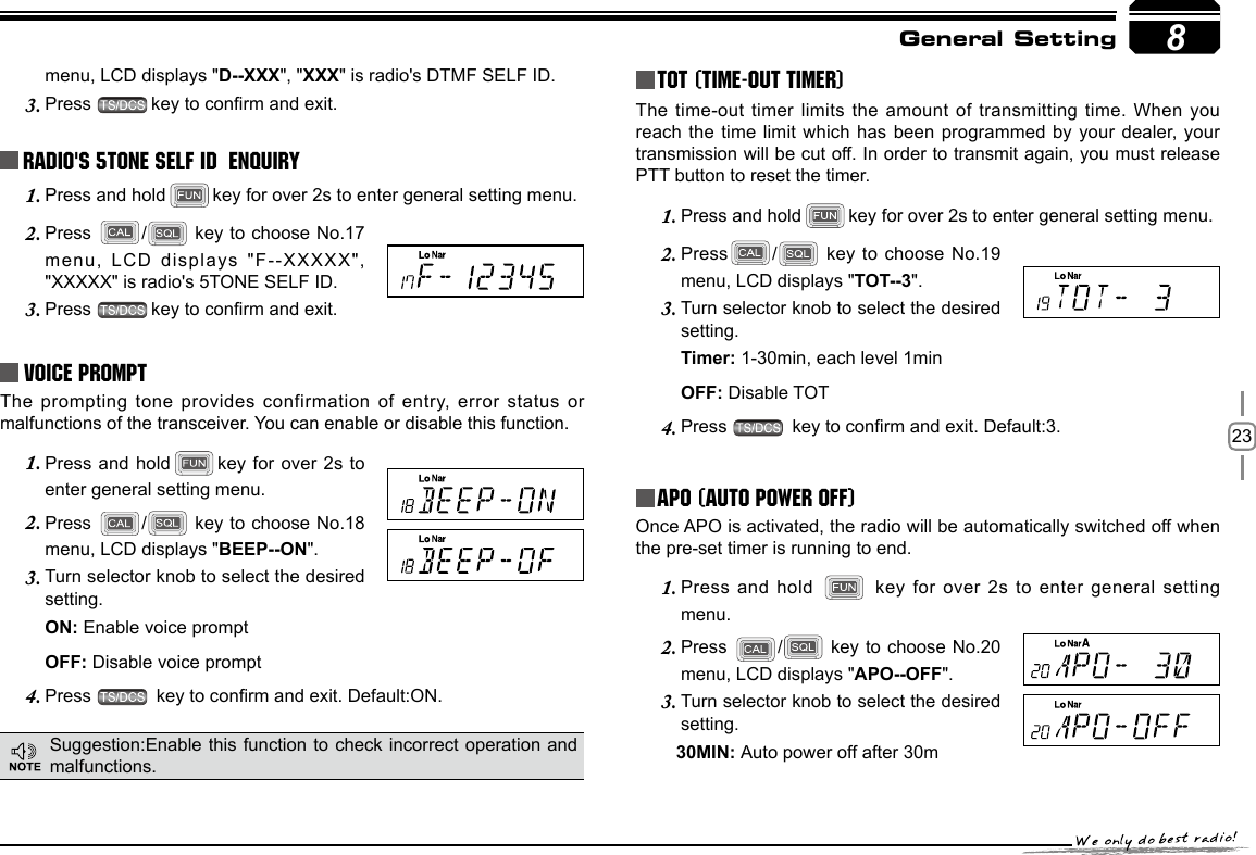
![299TOT (Time-out timer)The time-out timer limits the amount of transmitting time. When you reach the time limit which has been programmed by your dealer, your transmission will be cut off. In order to transmit again, you must release PTT button to reset the timer.In standby, press 1. , then press LCD displays "TOT-X". Press [ 2. / ] to select the desired value.Press number key to conrm and exit.3. CTCSS/DCS Encode and DecodeIn standby, press 1. , then press to enter into CTCSS/DCS Encode and Decode.Repeat above operation to set as below:2. LCD displays icon, it indicates CTCSS encode set in current channel.LCD displays and icon, it indicates CTCSS encode and decode set in current channel.LCD displays DCS icon, it indicates DCS encode and decode set in current channel.In corresponding icon, press [ 3. / ] to select the desired CTCSS/DCS encode and decode.Press 4. , , or to conrm and exit.Talk Around This function can be temporarily used in Channel mode. Once the radio is turned off or switched to another channel, the temporary setting will be erased and back to initial settings. By Talk Around function, you can directly communicate with other radios in your group in case the repeater is not activated or when you are out of the repeater range. The transceiver will transmit by RX frequency with its CTCSS/DCS signaling.In standby, press 1. , then press key, LCD displays "TALK--OF".Press [ 2. / ] to select the desired setting. ON:Enable Talk Around OFF:Disable Talk AroundPress number key to conrm and exit.3. This function can be temporarily used in Channel mode. Once the radio is turned off or switched to another channel, the temporary setting will be erased and back to initial settings.Voice PromptThe prompting tone provides confirmation of entry, error status or malfunctions of the transceiver. You can enable or disable this function.In standby, press 1. , then press , LCD displays "BEEP--XX".Press [ 2. / ] to turn on/off BEEP voice prompt. BEEP—OF: turn off voice prompt BEEP—ON: turn on voice promptPress number key to exit and store.3. Microphone Operation](https://usermanual.wiki/Qixiang-Electron-Science-and-Technology/AT778UV.User-Manual/User-Guide-2487677-Page-34.png)
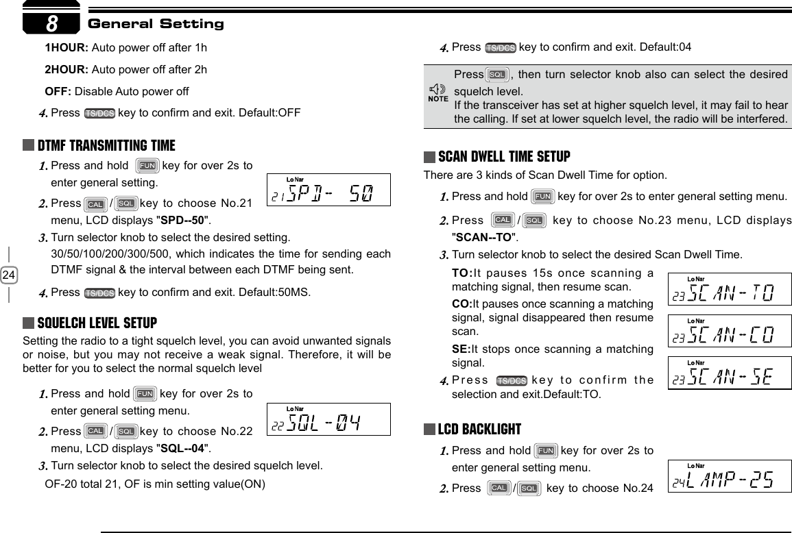
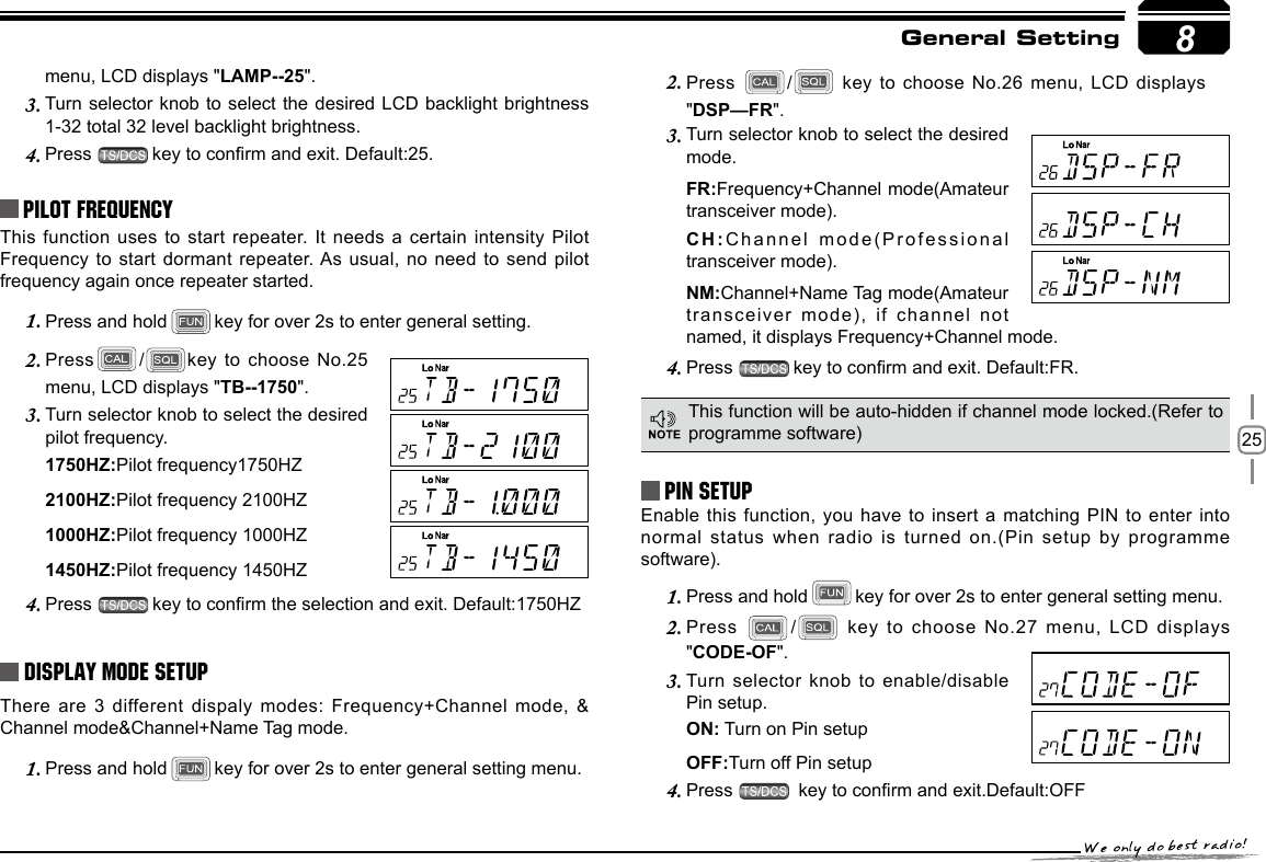
![309 LCD Backlight In standby status, press 1. , then press LCD displays "LAMP-XX".Press [ 2. / ] to select desired backlight brightness(1-32 levels).Press number keys to conrm and exit.3. Microphone Operation](https://usermanual.wiki/Qixiang-Electron-Science-and-Technology/AT778UV.User-Manual/User-Guide-2487677-Page-35.png)
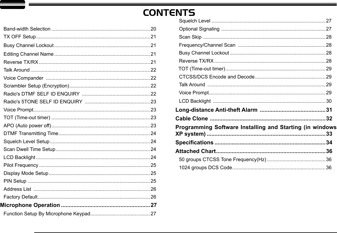
![3110This function is mainly use for simple anti-theft alarm device in vehicles. When the transceiver be removed in an improper manner, the transceiver will emit and transmit alarming and background voice to system and other transceiver of the same frequency.Steering-wheel etc.Alarm cable [QL-01(B)]DC power cableBatteryAlarm cable [QL-01(A)]Long-distance Anti-theft Alarm Connect DC power cable with car battery.Connect the optional alarm cable QL-01(A) to the data jack on 1. the front panel as shown. Secure the other end of the cable to an object that stays xed in vehicle. (Note: if alarm cable QL-01 (A) is not enough long, you can choose optional alarm cable QL-01 (B) to extend).When transceiver power off by press 2. key, the long-distance anti-theft alarm enable.When the alarm cable QL-01(A) or QL-01(B) is removed from the 3. DATA jack or cut by improper sequence, the alarm function enable and will alarm as programmed. In alarming, the transceiver will stop alarm once receiving a matching signal. And alarm again when a matching signal disappeared.Restart radio to cancel anti-theft alarming.Reconnect with alarm 4. cable and turn off radio, the system will return to alarm mode.The long-distance anti-theft alarm only available when transceiver power off.](https://usermanual.wiki/Qixiang-Electron-Science-and-Technology/AT778UV.User-Manual/User-Guide-2487677-Page-36.png)
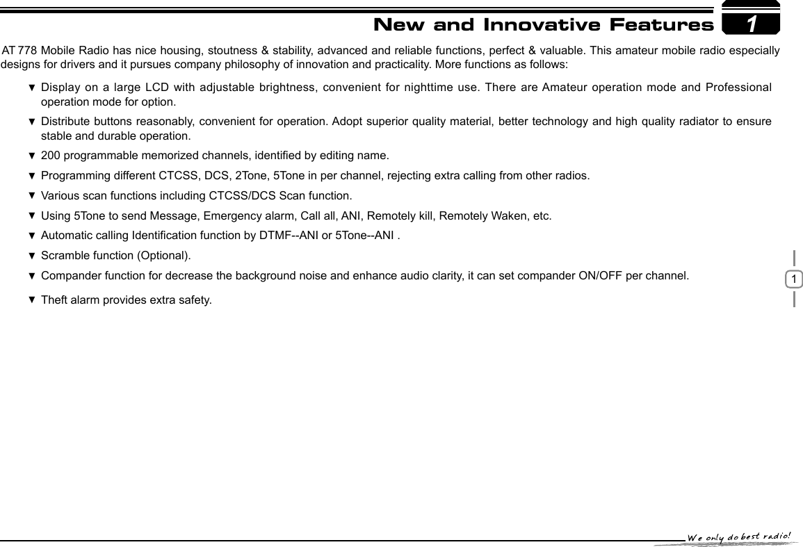
![3211This feature will copy the programmed data and parameters in the master unit to slave units. It copies the parameters and memory program settings.Use optional CP50 cloning cable, connect the cable between the data jacks on both master and slave.1. Press and hold key, then press key to enter into cloning mode, LCD displays "2. CLONE".Press master unit's [PTT] key, LCD displays "3. SD XXX", "XXX" indicates data volume in transmitting. Slave unit displays "LD XXX", "XXX" indicates received data volume. When the transmission is successfully nished, the master and slave unit both display "PASS". Turn off the power, disconnect the cable and repeat step 2 to step 3 operations to clone the next slave unit.Cable CloneIf the data is not successfully transmitted, turn off both units, make sure the cable connection is correct and repeat the entire operation from the beginning.](https://usermanual.wiki/Qixiang-Electron-Science-and-Technology/AT778UV.User-Manual/User-Guide-2487677-Page-37.png)