Qsc Hpr122I Hpr152I Hpr153I Hpr151I Hpr181I Users Manual TD 000212 00
HPR122i, HPR152i, HPR153i, HPR151i, HPR181i to the manual d2258a40-baa5-4612-a1f7-c5d9e88b018d
2015-02-05
: Qsc Qsc-Hpr122I-Hpr152I-Hpr153I-Hpr151I-Hpr181I-Users-Manual-394872 qsc-hpr122i-hpr152i-hpr153i-hpr151i-hpr181i-users-manual-394872 qsc pdf
Open the PDF directly: View PDF ![]() .
.
Page Count: 24
1675 MacArthur Blvd., Costa Mesa, CA, 92626 USA
Main Number (714) 754-6175 or toll free (USA only) (800) 854-4079
Customer Service(714) 957-7150 or toll free (USA only) (800) 772-2834
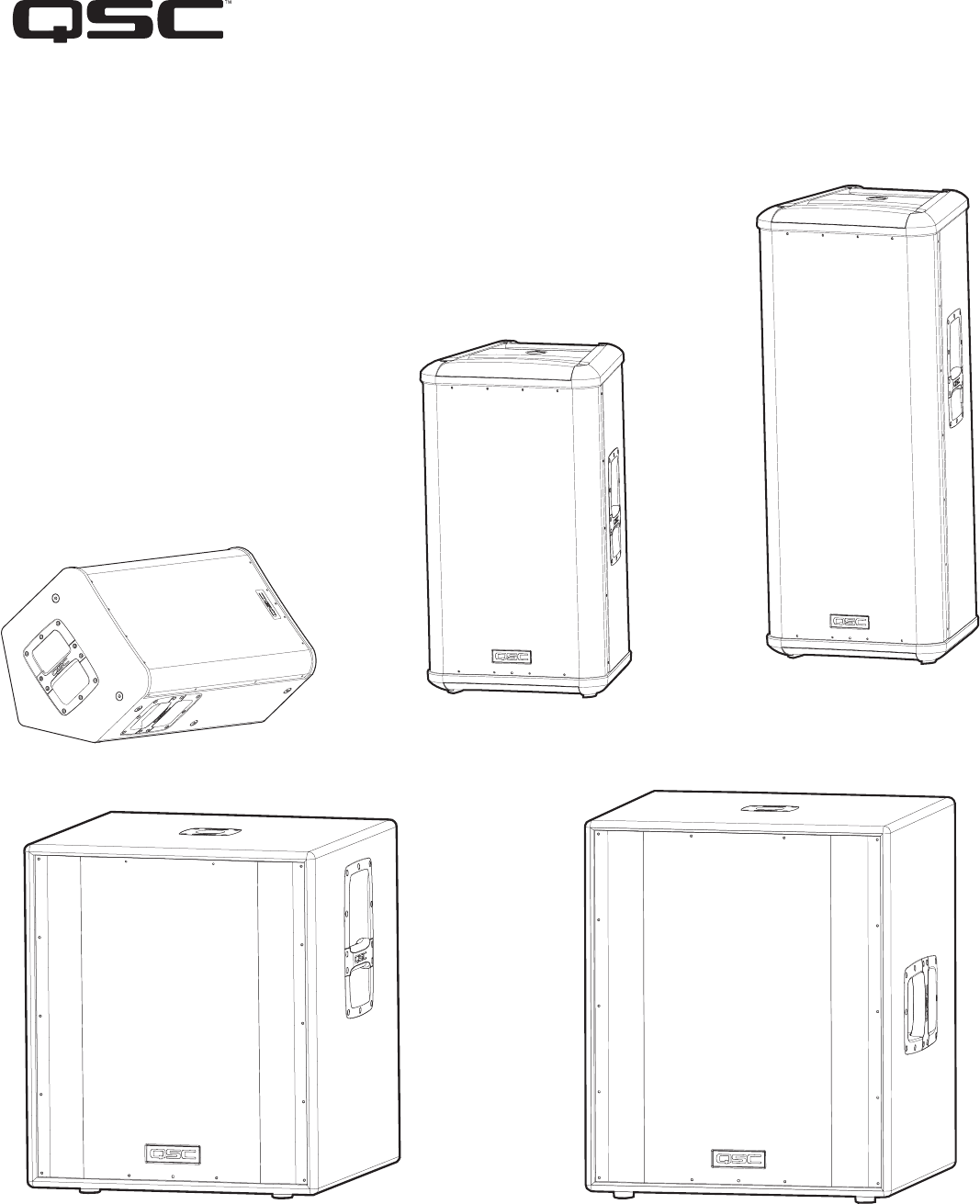
HPR Series Powered Loudspeaker Products
User Manual
HPR122i 12-inch two-way
HPR152i 15-inch two-way
HPR153i 15-inch three-way
HPR151i 15-inch subwoofer
HPR181i 18-inch subwoofer
*TD-000234-00*
TD-000234-01 rev.B

2
Important Safety Precautions & Explanation of Symbols
Install in accordance with QSC Audio Product's instructions and under the supervision of a licensed Professional Engineer.
WARNING!
CAUTION: TO REDUCE THE RISK OF ELECTRIC SHOCK, DO NOT REMOVE THE COVER.
NO USER-SERVICEABLE PARTS INSIDE. REFER SERVICING TO QUALIFIED PERSONNEL.
The lightning flash with arrowhead symbol within an equilateral triangle is intended to alert the user to the pres-
ence of uninsulated “dangerous” voltage within the product's enclosure that may be of sufficient magnitude to
constitute a risk of electric shock to humans.
The exclamation point within an equilateral triangle is intended to alert the user to the presence of important
operating and maintenance (servicing) instructions in this manual.
1- Read these instructions.
2- Keep these instructions.
3- Heed all warnings.
4- Follow all instructions.
5- WARNING: To prevent fire or electric shock, do not expose this equipment to rain or moisture. Do not use this apparatus near water.
6- Clean only with a dry cloth.
7- Allow a minimum of 6” (152mm) clearance at cabinet back for convection cooling. Keep anything that might restrict airflow away from the rear of the enclosure
(i.e draperies, fabric, etc...). Do not block any ventilation openings. This product contains an internal power amplifier that produces heat.
8- Do not install near any heat sources such as radiators, heat registers, stoves, or other apparatus (including amplifiers) that produce heat.
9- Do not defeat the safety purpose of the grounding-type plug. The grounding plug has two blades and a grounding prong. The third prong is provided for your
safety. If the provided plug does not fit your outlet, consult an electrician for the replacement of the obsolete outlet. Do not cut off the grounding prong or use an
adapter that breaks the grounding circuit. This apparatus must be properly grounded for your safety.
10- Protect the power cord from being walked on or pinched, particularly plugs, convenience receptacles, and the point where they exit from the apparatus.
11- This product is not equipped with an all-pole mains switch. To fully disconnect from the AC mains, the AC plug must be removed from the AC outlet or the
appliance coupler (IEC block) must be removed from the amplifier module. Ensure either the AC line cord plug or the appliance coupler are accessible in case
of emergency disconnect requirement.
12- Use only attachments/accessories specified by QSC Audio Products, Inc.
13- Use only with hardware, brackets, stands, and components sold with the apparatus or by QSC Audio Products, Inc.
14- Unplug the apparatus during lightning storms or when unused for long periods of time.
15- Refer all servicing to qualified service personnel. Servicing is required when the apparatus has been damaged in any way, such as power supply cord or
plug is damaged, liquid has been spilled or objects have fallen into the apparatus, the apparatus has been exposed to rain or moisture, does not operate normally,
or has been dropped.
16- Before placing, installing, rigging, or suspending any speaker product, inspect all hardware, suspension, cabinets, transducers, brackets and associated
equipment for damage. Any missing, corroded, deformed, or non-load rated component could significantly reduce the strength of the installation or placement.
Any such condition severely reduces the safety of the installation and should be immediately corrected. Use only hardware which is rated for the loading con-
ditions of the installation and any possible short-term, unexpected overloading. Never exceed the rating of the hardware or equipment.
17- Consult a licensed, Professional Engineer regarding physical equipment installation. All local, state and national regulations regarding the safety and oper-
ation of equipment are understood and adhered to.
18- HPR152i WARNING! Do not use a loudspeaker support pole longer than 26” (660mm) when supported by QSC’s HPR151i or HPR181i subwoofer.
19- HPR122i WARNING! Do not use a loudspeaker support pole longer than 31” (787mm) when supported by QSC’s HPR151i or HPR181i subwoofer.
20- Do not use the HPR152i, HPR153i, HPR151i, or HPR181i oriented horizontally. Horizontal orientation can cause overheating and thermal limiting. The cooling
fins on the amplifier module must be vertically oriented in order to efficiently dissipate the heat generated by the amplifier.
21- The appliance shall not be exposed to dripping or splashing and no objects filled with liquids, such as vases, shall be placed on the apparatus.
3
Introduction
Congratulations and thank you for your purchase of this professional, powered loudspeaker product. To get the most from your investment, we
recommend you review all the information provided in this User Manual.
The HPR self-powered loudspeakers provide excellent sound quality, durable construction and clean, efficient, on-board amplification. Amplifi-
ers are matched to the drivers with active equalization and precise crossover control. Active power limiting and thermal management extends
the life of drivers and the amplifier. The HPR series solves many application challenges with its great sound, built-in protection systems and self-
contained portability. HPR is the perfect solution for public performances, corporate events and private parties demanding flexible and excellent
sounding system solutions.
All models are self-powered using efficient amplifiers. AC line connection is fast and easy; an IEC-style quick-disconnect ensures reliable AC
mains connection while providing an easy-to-remove power cord for cabinet mobility. Audio enters the self-powered loudspeaker via a female
XLR connector with an additional parallel-wired male XLR output for daisy-chaining. No outboard signal processing is required as all models fea-
ture on-board filtering. The two-way and three-way full-range loudspeakers feature a switchable 100 Hz low-cut filter for use when subwoofers
are part of the system. Subwoofer models have two full-range input connectors (left and right) and two sets of output connectors; one pair fea-
turing a 100 Hz low-cut filter and one pair passing full-range signal.
Rear-panel LEDs alert the user to AC power status, input signal presence, and limiter operation. Additionally, a blue front-panel "power on" LED
provides valuable visual power confirmation. It can also be disabled for applications where light toward the audience
may interfere with stage aesthetics. All models feature a 21-step detent Gain control allowing precise control and repeatable setup. The enclo-
sures are made of high-quality plywood and are texture-coated in black. The models HPR122i, HPR152i and HPR153i have integral M10 suspen-
sion points for permanent installation and "flying" applications. Features vary by model, so please refer to sales brochures or the specifications
section of this manual for specific model information.
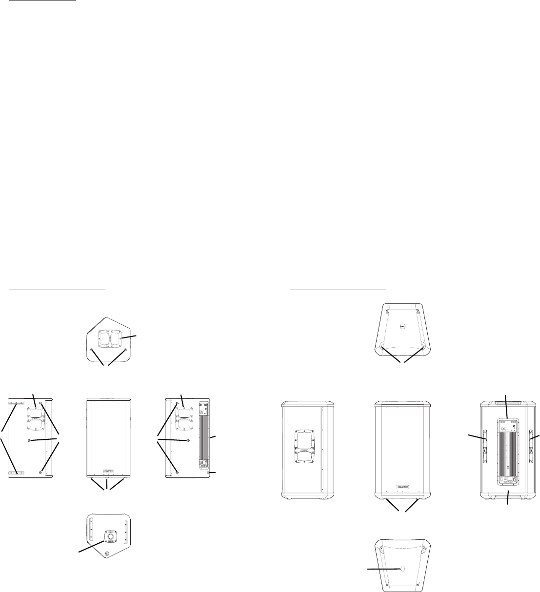
HPR122i Features HPR152i Features
1- Pole Cup 4- Power Amplifier
2- Handles 5- Slip-resistant Feet
3- Grill 6- Rigging points
1
3
4
5
6
2
2
3
4
6
1
22
2
5
66
6
5
6
4
HPR153i Features
1- Power Amplifier 4- Slip-resistant Feet
2- Handles 5- Rigging Points
3- Grill
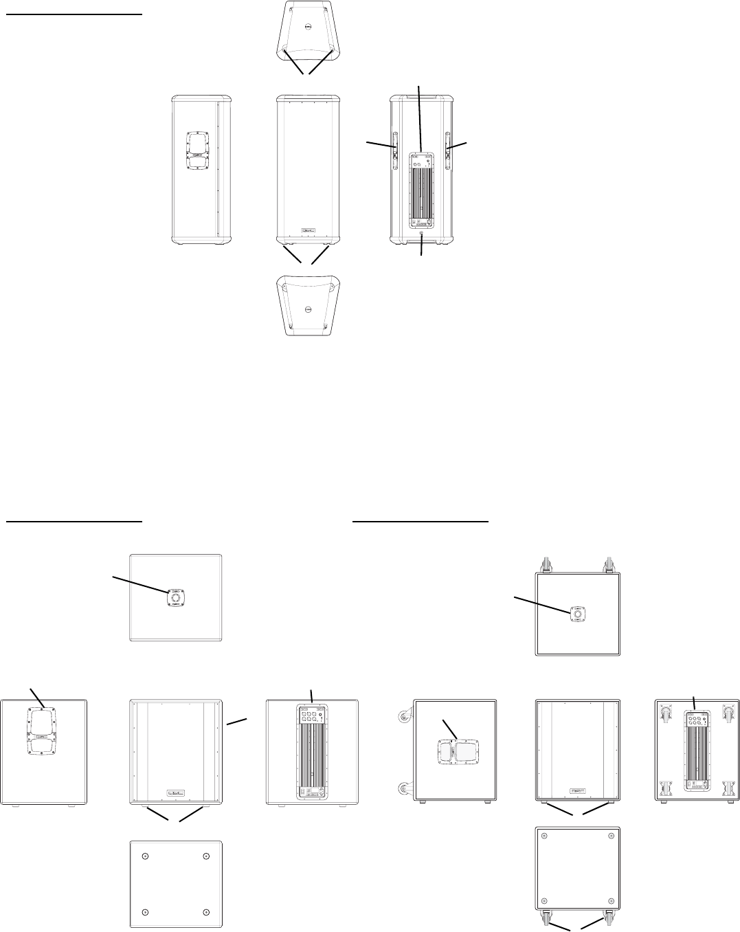
HPR151i Features HPR181i Features
1- Pole Cup 4- Power Amplifier
2- Handles 5- Slip-resistant Feet
3- Grill 6- Casters (HPR181W only)
3
2
5
1
2
4
5
3
2
5
1
2
4
5
4
1
2
3
6
5
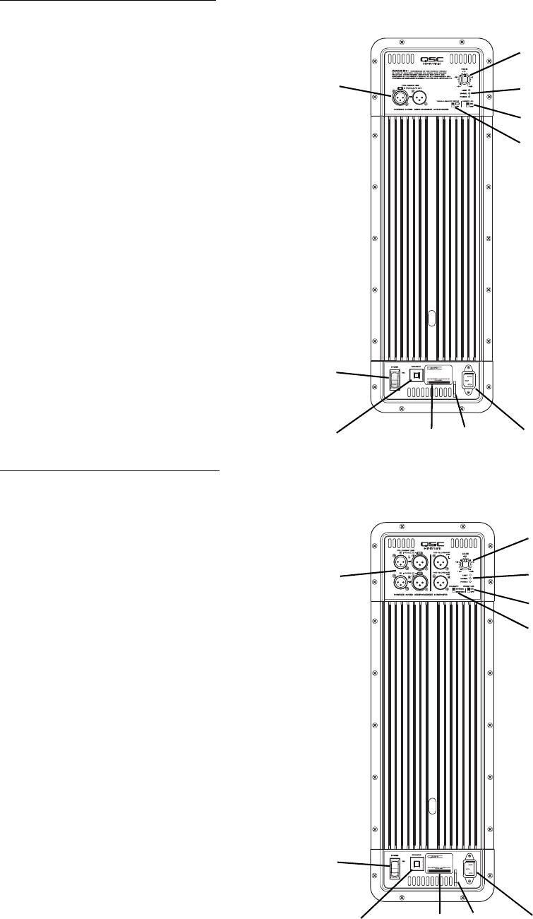
Full Range Amplifier Detail
1- Input and Output Connector(s)
2- Gain Control
3- Power, Signal, and Clip LED Indicators
4- Front LED Switch
5- 100 Hz Low-Cut Filter Switch
6- Power Switch
7- Circuit Breaker
8- Serial Number Plate
9- Power Cord Tether Lance
10- IEC Power Inlet
Subwoofer Amplifier Detail
1- Input and Output Connector(s)
2- Gain Control
3- Power, Signal, and Clip LED Indicators
4- Front LED Switch
5- Polarity Switch
6- Power Switch
7- Circuit Breaker
8- Serial Number Plate
9- Power Cord Tether Lance
10- IEC Power Inlet
3
2
6
1
4
5
78910
3
2
4
5
8910
6
1
7
6
Installation
Before placing, installing, rigging, or suspending any speaker product, inspect all hardware, suspension, cabinets, transducers, brackets
and associated equipment for damage. Any missing, corroded, deformed, or non-load rated component could significantly reduce the
strength of the installation or placement. Any such condition severely reduces the safety of the installation and should be immediately
corrected. Use only hardware which is rated for the loading conditions of the installation and any possible short-term, unexpected over-
loading. Never exceed the rating of the hardware or equipment.
Consult a licensed, Professional Engineer regarding physical equipment installation. Ensure that all local, state and national regulations
regarding the safety and operation of loudspeakers and related equipment are understood and adhered to.
How They Should Be Used
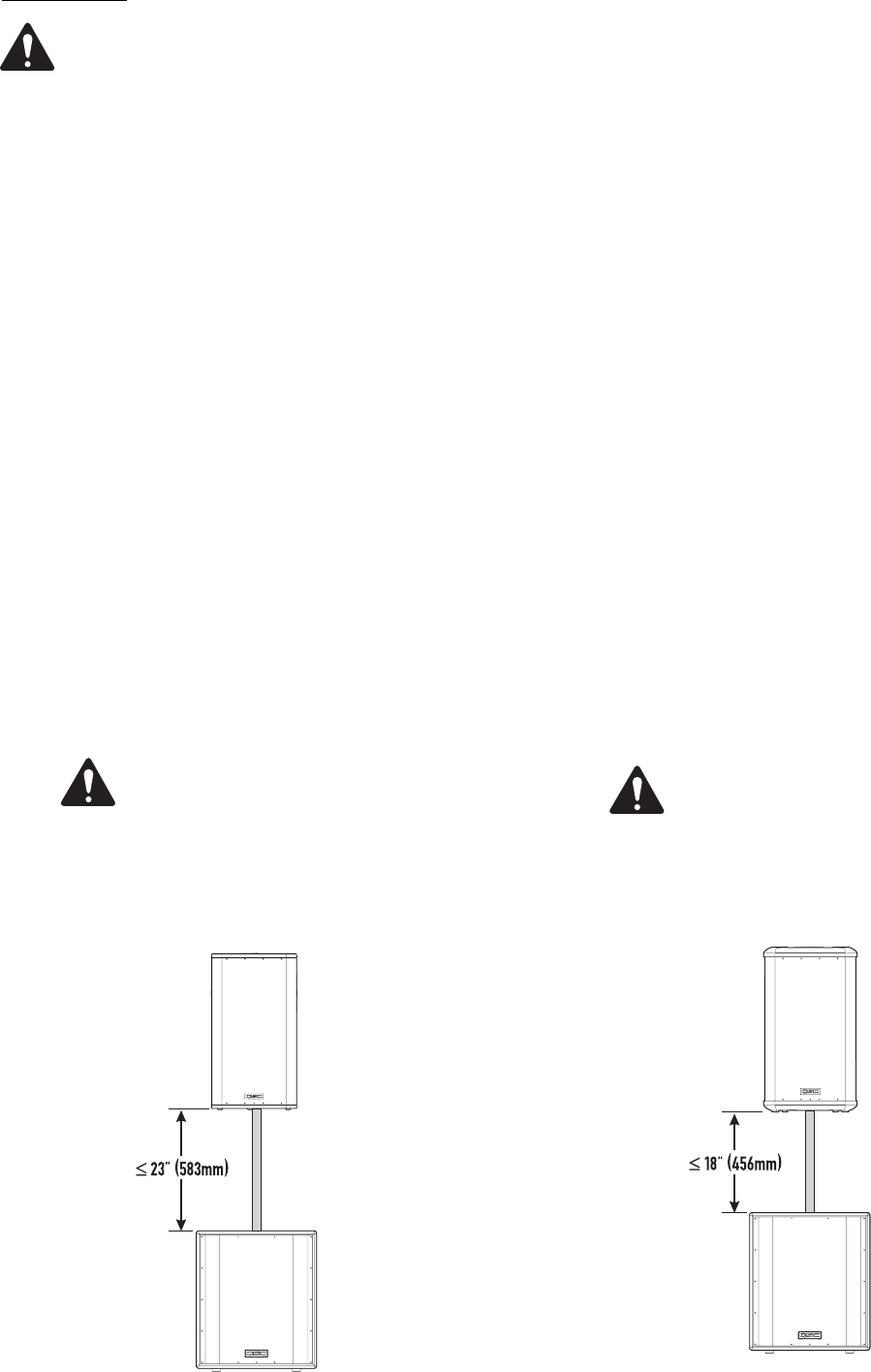
HPR122i: The HPR122i was designed to sit on the floor, stage, subwoofer enclosure, be suspended, or be pole mounted on a 35mm diameter
loudspeaker support pole. The pole can be part of a stand-alone loudspeaker stand or be inserted into the pole cup of the HPR151i or
HPR181i. Pole length must be no longer than 31” (787mm) when supported by the HPR151i or HPR181i subwoofer.
HPR152i: The HPR152i was designed to sit on the floor, stage, subwoofer enclosure, be suspended, or be pole mounted on a 35mm diameter
loudspeaker support pole. The pole can be part of a stand-alone loudspeaker stand or be inserted into the pole cup of the HPR151i or
HPR181i. Pole length must be no longer than 26” (660mm) when supported by the HPR151i or HPR181i subwoofer.
HPR153i: The HPR153i was designed to be suspended, or sit on the floor, stage, or on top of the subwoofer enclosure. Do not attempt to pole
mount this loudspeaker! There is no pole cup provided.
HPR151i: The HPR151i was designed to sit on the floor or on the stage. A pole cup on the top of the enclosure accepts 35mm loudspeaker
mounting poles. Rubber feet on the enclosure’s bottom help to minimize enclosure movement during operation. Do not pole mount or stack
more than one enclosure on top of the HPR151i enclosure.
HPR181i: The HPR181i was designed to sit on the floor or on the stage. A pole cup on the top of the enclosure accepts 35mm loudspeaker
mounting poles. Rubber feet on the enclosure’s bottom help to minimize enclosure movement during operation. Do not pole mount or stack
more than one enclosure on top of the HPR181i enclosure. As the casters will wear during normal use, it may be required to insert small foam
pieces between the wheels and frames to minimize rattling at high output levels.
HPR122i WARNING!
Do not use a loudspeaker support
pole longer than 31” (787mm)
when supported by the HPR151i or
HPR181i subwoofer. Note- each
pole cup is approximately 4”
(102mm) deep.
HPR152i WARNING!
Do not use a loudspeaker support
pole longer than 26” (660mm)
when supported by the HPR151i or
HPR181i subwoofer. Note- each
pole cup is approximately 4”
(102mm) deep.
7
Installation (continued)
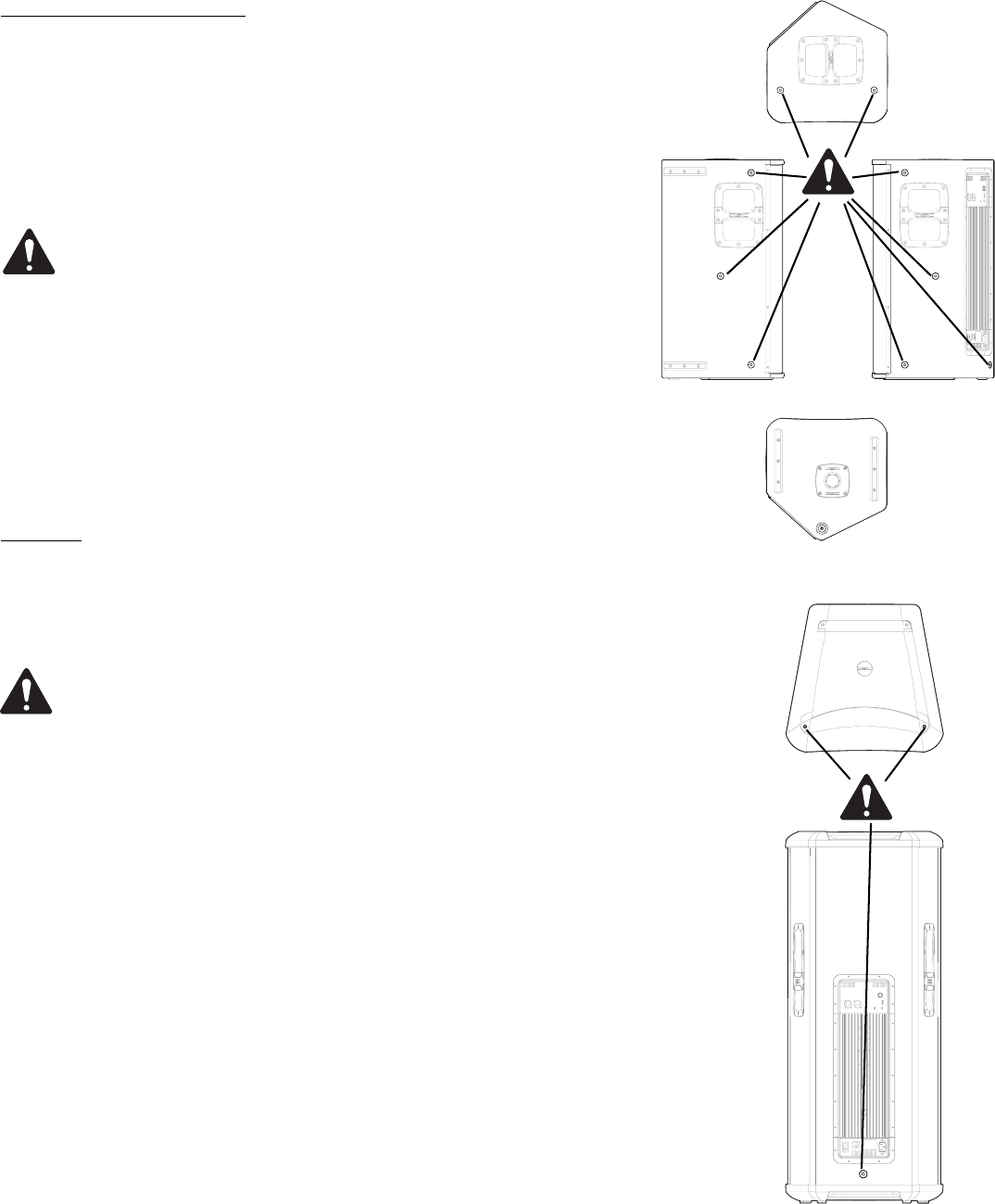
Pick Points (suspended installations)
The HPR152i and HPR153i enclosures feature three load-rated pick points.
The HPR122i enclosure features nine load-rated pick points. As shipped
from the factory, each pick point has a bolt or plug installed to retain the
air-tight design of the enclosure. Never operate the loudspeaker with the
pick points open (unsealed) as it will degrade the performance of the
product.
Ensure all pick-point fasteners are installed and correctly
tightened in order to maintain enclosure’s rated strength.
Additionally, air leaks resulting from missing hardware will
degrade the loudspeaker’s performance.
Use only QSC’s M10 forged shoulder eye bolts. Contact QSC
Technical Services department for complete information.
Cooling
This is a self-powered loudspeaker containing an internal power amplifier
that produces heat. Allow a minimum of 6” (152mm) clearance at cabinet
back for convection cooling. Keep anything that might restrict airflow
away from the rear of the enclosure (i.e draperies, fabric, etc...).
Do not use the HPR152i, HPR153i, HPR151i, or HPR181i oriented
horizontally. Horizontal orientation can cause overheating and
thermal limiting. The cooling fins on the amplifier module must be
vertically oriented in order to efficiently dissipate the heat gener-
ated by the amplifier.
Do not install enclosures with their rear panels exposed to direct
sunlight. Direct sunlight will heat the amplifier module and reduce
its ability to produce full output. Install sunshades if the applica-
tion merits.
Maximum ambient temperature for full performance to specifica-
tion is 40° C. (104° F.).
Do not install enclosures where exposed to rain or other water
sources. The enclosure is not weatherproof. Outdoor installations
must provide protection from the elements.
Pickpoints on the
HPR122i
Pickpoints on the
HPR152i and
HPR153i
8
AC Mains
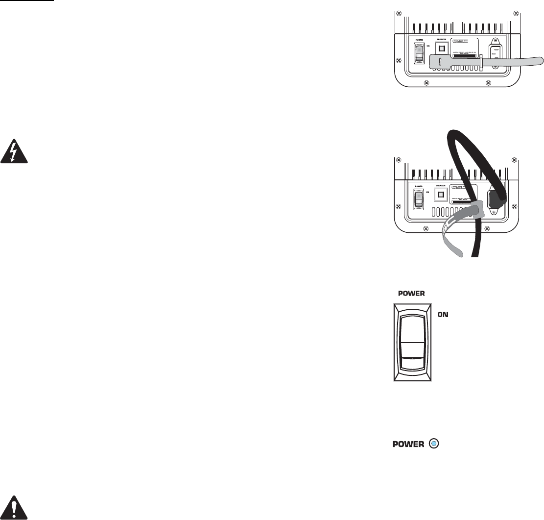
Connect AC power to the IEC socket on the back of the amplifier by locating
the IEC connector-end of the AC power cord and inserting it fully into the IEC
inlet on the power amplifier module. NOTE: Turn off the AC power switch
before connecting AC power.
An AC power cord hook-and-loop tether (retention strap) is provided to mini-
mize the risk of the power cord being inadvertently pulled from its connection
at the back of the amplifier. To use the tether, pass it through the chassis
lance (adjacent the IEC socket) and then capture the AC power cord by loop-
ing it in the tether before closing the hook-and-loop strap.
The correct AC line voltage is shown on the serial number label, on
the rear panel. Connecting to the wrong line voltage may damage the
amplifier or increase the risk of electric shock.
AC Mains Disconnection
Turn the AC power switch to the off position. To remove the AC mains cord,
grasp the IEC connector’s plastic body and pull, removing the connector from
the socket.
Power Switch
Push in on the top of the rocker switch to apply AC mains power to the pow-
ered loudspeaker. Push in on the bottom of the rocker switch to turn the pow-
ered loudspeaker off.
When turned on, the blue POWER indicator LED and the red LIMIT (limiter)
indicator LED will illuminate; after a few seconds the red LIMIT indicator will
extinguish.
LED POWER Indicator
The blue LED POWER indicator will illuminate when the AC Power switch is
in the “ON” position, the AC mains power cord is connected properly, and the
AC mains are functioning properly. The LED POWER indicator will extinguish
when the AC Power switch is in the “off” position or AC mains power has
been removed from the loudspeaker.
If the POWER indicator does not illuminate when the Power switch is placed
in the “on” position, verify the AC mains line cord is properly attached to the
loudspeaker and plugged into the AC outlet. Verify the outlet is functioning
properly.
If the AC mains cordset is serviceable and the AC mains outlet is oper-
ating properly, but the loudspeaker fails to operate, the loudspeaker
may require servicing. Contact QSC’s Technical Services department.
System Power Sequencing
Proper power turn on sequence can help to prevent unexpected sounds from
your system (pops, clicks, thumps). These unintended sounds can damage
drivers and cause audience members to question the professionalism of the
sound team. Turn on and off the system in the proper order to avoid unex-
pected sounds.
Power On Sequence: Turn on all source devices (CD players, mixers), turn
on subwoofer, then turn on the “top-boxes” (HPR122i, HPR152i and HPR153i).
Power Off Sequence: Turn off the top-boxes, turn off the subwoofer, then
turn off the source devices.
AC power switch
Power “on” indicator LED
AC power cord
tether use-
1- Insert tether
through chassis
lance adjacent IEC
inlet.
2- Form a small
loop in the AC
power cord. Cap-
ture the AC power
cord in the tether
and secure by pull-
ing the smaller end
through the hole in
the tether’s large
end.
9
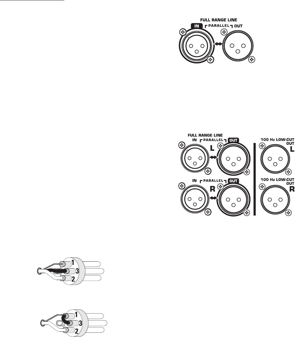
Input Connections
Full-range models have one female XLR line-level input marked
FULL RANGE LINE IN.
Subwoofers have a second set of connectors, one for the left
channel’s audio and one for the right channel’s audio.
We recommend balanced connections be used. Balanced con-
nections will reduce AC hum and interference, especially with
long cable runs. Unbalanced connections may be suitable for
short cables. The input impedance is 22k ohm for balanced con-
nections or 11k ohm for unbalanced connections. The signal's
source impedance should be less than 600 ohms.
HPR122i, HPR152i and HPR153i: Insert the male XLR input
into the jack marked FULL RANGE LINE IN. Ensure the connector
is fully seated.
HPR151i and HPR181i: Insert the left channel’s XLR input into
the left channel’s (L) FULL RANGE LINE IN connector. Insert
the right channel’s XLR connector into the right channel’s (R)
FULL RANGE LINE IN connector. If a single input signal is
used, plug into either the L (left) or R (right) channel’s input.
If two input signals are used, plug the left channel’s signal
into the connector marked FULL RANGE LINE IN L (the top
input connector) and the right channel’s signal into the con-
nector marked FULL RANGE LINE IN R (the bottom input con-
nector). When two input signals are applied, the subwoofer’s
gain is automatically increased 6dB as the subwoofer will
likely be used with two full-range loudspeakers.
Balanced inputs: Connect to the plug as shown.
Unbalanced inputs: Connect to the plug as shown. Pin 3 and
pin 1 must be connected with a jumper as shown.
1= shield (ground)
3= jumper to pin 1
2= plus (+)
1= shield (ground)
3= minus (-)
2= plus (+)
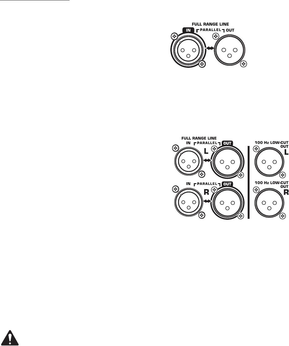
Full-range loudspeaker’s Input
(IN) and Output (OUT) Connectors
Subwoofer loudspeaker’s Input (IN)
and Output (OUT) Connectors
10
Output Connections
Full-range models have one XLR output connector marked
FULL RANGE LINE OUT. The output connector is wired in
parallel with the input enabling connection of multiple
enclosures in a “daisy-chain” fashion.
Subwoofer models have two sets of output connectors,
one set for the left and one set for the right audio chan-
nel. Each channel has a FULL RANGE LINE OUT connector
and a 100 Hz LOW-CUT OUT connector (active 100 Hertz
filter applied, non-defeatable).
We recommend balanced connections be used. Balanced
connections will reduce AC hum and interference, espe-
cially with long cable runs. Unbalanced connections may
be suitable for short cables.
HPR122i, HPR152i and HPR153i
Insert the XLR connector into the jack marked FULL
RANGE LINE OUT. Connect the other end of the cable to
the next down-stream audio device’s input connector. The
output connector is wired in parallel with the input con-
nector and is not effected by the 100 Hertz low-cut filter
switch setting.
HPR151i and HPR181i
FULL RANGE LINE OUT: Use the outputs marked FULL
RANGE LINE OUT (Left and/or Right) when connecting to
down-stream powered loudspeakers which accept full-
range audio or have their own filtering.
100 Hz LOW-CUT: Use the outputs marked 100 Hz LOW-
CUT OUT (L and/or R) when connecting to downstream
powered loudspeakers that have no low-frequency filter-
ing but the low-frequency roll-off is desired. Do not use
the 100 Hz LOW-CUT OUT connectors for connecting to
other subwoofers. Instead, use the FULL RANGE LINE
OUT. Be sure to turn off any loudspeaker connected to the
100 Hz LOW-CUT OUT before turning off the subwoofer’s
AC power. This prevents any undesired turn-off transients
(thumps, bumps) in the connected devices.
If using the subwoofer’s 100 Hz LOW-CUT OUT
connector to provide signal to the top-boxes
(HPR152i and HPR153i), be sure the top-box’s low-
cut filters are OFF. Do not apply a second filter as
the sonic performance of the system will be nota-
bly degraded.
IMPORTANT! If using full range loudspeakers
from another manufacturer, we recommend they
be connected to the QSC subwoofer’s 100 Hz LOW-
CUT OUT. This will ensure proper phasing of the
full range loudspeaker with respect to the sub-
woofer.
Full-range loudspeaker’s Input (IN)
and Output (OUT) Connectors
Subwoofer loudspeaker’s Input (IN)
and Output (OUT) Connectors
11
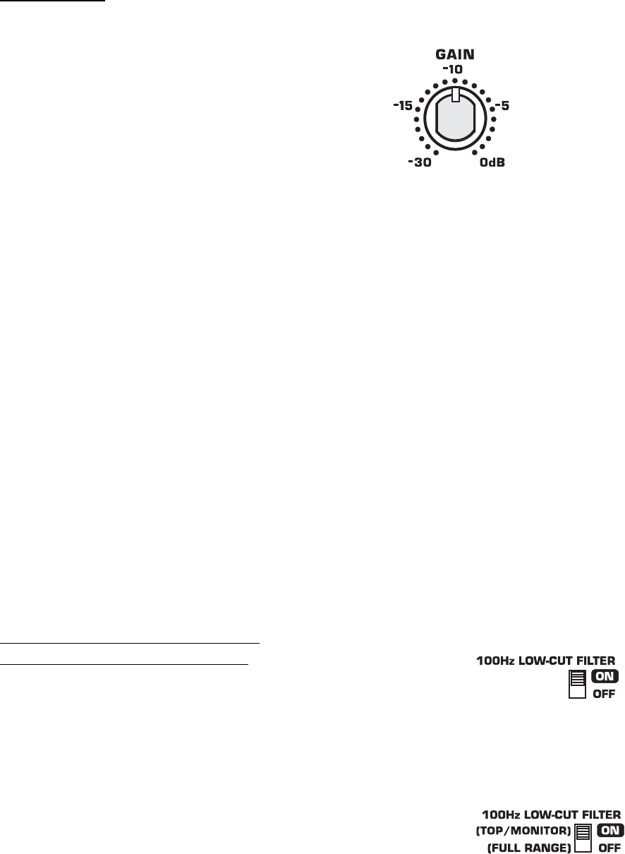
GAIN Control
The GAIN control is marked in dB of attenuation. There are
21 detents for repeatable adjustments. Turn the GAIN con-
trol clockwise to increase gain and counter clockwise to
decrease gain.
The upper 14 steps are about 1 dB each and settings
should normally be made within this range. When operat-
ing with the GAIN set below -15 dB, it may be possible to
exceed input headroom. If this is the case, reduce the input
signal strength and increase the gain of the loudspeaker
amplifier.
Subwoofer Gain Notes
Scenario: One input signal only to the subwoofer,
one full-range loudspeaker for each subwoofer- The
HPR loudspeakers are designed to be used as a system,
typically using one subwoofer for each full-range loud-
speaker. If the subwoofer and the full-range loudspeaker
have their Gain controls set identically, the tonal balance
will be correct (or very close to correct).
Scenario: Two input (L+R) signals to the subwoofer,
and two full-range loudspeakers per subwoofer-
When two inputs (L+R) are applied to the subwoofer, an
additional gain of 6dB is automatically applied to the sub-
woofer. The additional gain is added to the subwoofer to
keep the tonal balance correct for use with two full-range
loudspeakers.
100 Hertz Low-Cut Filter Switch:
HPR122i, HPR152i, and HPR153i
Below the LED indicators is a small recessed slide-switch
that enables or disables a 100 Hertz low-cut filter.
Filter OFF (Full Range)
Turn the filter OFF when using without subwoofers or dedi-
cated low-frequency enclosures.
Filter ON (100 Hz Low-Cut)
Turn the filter ON when using with optional subwoofers or
low-frequency systems. This results in proper subwoofer
operation and allows the top box to provide improved clar-
ity in the middle and high frequencies. HPR122i: If using
as a floor monitor, turn the filter ON for improved vocal
range clarity and to reduce low frequency build-up on
stage.
Gain control.
HPR152i and HPR153i 100 Hertz low-cut filter switch.
HPR122i 100 Hertz low-cut filter switch.
12
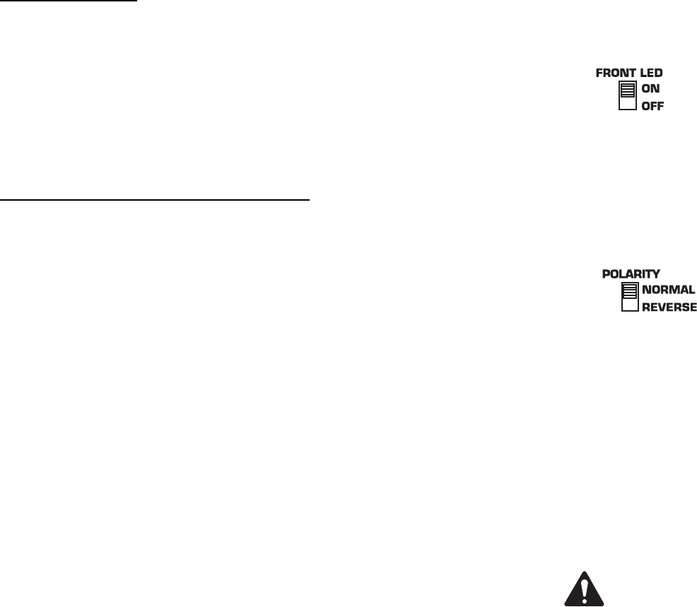
Front LED Switch
The Front LED Switch, located on the rear panel, is used to enable or disable
the LED located on the front of the enclosure near the bottom of the grill. Slide
the switch to the ON position to enable the front LED and slide it to the OFF
position to disable the front LED.
Most applications merit the use of the Front LED so power status can be visu-
ally confirmed, easily and quickly. For applications where the LED may distract
audience members, it is easily disabled by sliding the FRONT LED switch to
the OFF position.
Polarity Switch (HPR151i and HPR181i)
When all loudspeakers in system are properly polarized, a positive polarity
drive signal results in a forward excursion of all loudspeaker cones. This, in
turn, sets up a positive reinforcement of the sound wavefront (each loud-
speaker reinforces the actions of the other loudspeakers). This effect is most
pronounced at low (bass) frequencies.
If a loudspeaker is not properly polarized, its cone moves inward while the
properly polarized loudspeaker’s cones move outward. The inward movement
will effectively cancel the bass response of a similarly-sized driver in the sys-
tem, resulting in a reduction in the bass content.
It is critically important to maintain correct phasing in a loudspeaker system in
order to realize maximum performance. Polarity can be altered by miswired
input cables, interconnecting cables, mixer polarity switches set incorrectly,
just to name a few likely culprits.
To make matters a bit more complicated, phasing is also influenced by the
position of loudspeakers with respect to one another and by their position in a
given room. It is possible to have all loudspeakers polarized properly (electri-
cally) and yet achieve better bass response by having the subwoofer reverse
polarized. It is even possible to achieve improved bass response from the sys-
tem with multiple subwoofers polarized differently. Be aware that perceived
bass response also will change with the listener’s position, so move around
the room (venue) when testing your setup.
Because phasing problems can so drastically effect the bass output of a sys-
tem, the subwoofers are equipped with a switch marked POLARITY. When set
to NORMAL, the polarity is such that a positive going input will cause the cone
to move outward. When set to REVERSE, the input signal has its polarity
reversed and a positive going input will cause the loudspeaker’s cone to move
inward.
How to Use the Polarity Switch
When using QSC subwoofers and QSC full range loudspeakers, NORMAL
polarity will result in the best bass response IF the full range loudspeakers are
sitting on or very close to the subwoofers. If the subwoofers are some dis-
tance away from the full range loudspeakers, polarity change may be of bene-
fit.
Start with all subwoofer POLARITY switches in the NORMAL position. This
applies to systems with one subwoofer as well. Then, with your system at or
near expected operating levels, change the polarity of each subwoofer INDI-
VIDUALLY. Then walk around the venue and assess the overall bass response.
Select the polarity that results in the best overall system bass response.
Polarity switch.
IMPORTANT! If using full
range loudspeakers from
another manufacturer,
we recommend they be
connected to the QSC
subwoofer’s 100 Hz LOW-
CUT OUT. This will
ensure proper polarity of
the full range loud-
speaker with respect to
the subwoofer.
Front LED switch.

13
SIGNAL Indicator LED
The green SIGNAL indicator alerts the user to the presence of an input signal to the
HPR loudspeaker.
Normal Indication
The green SIGNAL indicator illuminates when the input signal exceeds -25 dB.
If No Indication
Check Gain settings and increase gain if necessary. Check input connections and
audio source for signal. If the red LIMIT LED illuminates, refer to the LIMIT indicator
section, below.
Abnormal Indication
If the green SIGNAL LED illuminates with no signal input, there may be system oscil-
lations or some other malfunction. Disconnect the input or fully reduce the gain. If
the green SIGNAL LED remains on, the amp may need servicing.
LIMIT Indicator LED
The red LIMIT indicator alerts the user to several conditions within the HPR loud-
speaker:
Continuous Bright Red Light
• Indicates protective mute mode.
• The speaker normally passes through muting for several seconds after applying
power, after which the light should go out, and sound should be heard.
• If the speaker enters Mute during operation, it has either overheated or developed a
fault.
• Overheating should correct itself within 1-2 minutes, after which sound should
resume. See below for a full explanation of thermal protection.
• Short periods of muting indicate a component fault. In this case AC power should be
removed and the speaker serviced.
Momentary Bright Red Flashes
• During operation, bright flashing indicates clipping (overdrive distortion). This is nor-
mally due to excessive volume and may be accompanied by audible distortion.
• If the loudspeaker mutes repeatedly during output peaks, there may be a component
fault; AC power should be removed and the loudspeaker serviced.
Continuous Half-bright Light
• Indicates that the internal limiter is reducing gain, due to prolonged clipping and/or
excessive temperature.
• After several seconds of severe clipping, the limiter will reduce power to protect the
speaker and improve the sound. This results in a steady, half-bright red indication.
Any further clipping will still result in bright flashes on top of the steady half-bright
indication. When the program level is reduced, the limiter will clear after several sec-
onds, and the red indicator will go out.
• If the power module overheats, the first response is to trigger limiting, to reduce vol-
ume and limit further temperature rise. This results in a steady half-bright illumina-
tion that does not clear even after reducing program level. It may take several
minutes for temperature to drop and clear the limiter. During this time, the exposed
heat sink will feel uncomfortably hot to the touch. If overheating continues, the
amplifier will ultimately mute, resulting in a full-bright red indication. When muting
clears, the amplifier will resume operation, with thermal limiting still active until it
further cools off.
• Overheating is usually caused by excessive ambient temperature, since the internal
temperature rise of the power module is relatively low. Protect the speaker from
excessive temperatures, such as being placed over a heater vent, or allowing direct
sunlight to impinge upon the heat sink surface.
LED indicators.
14
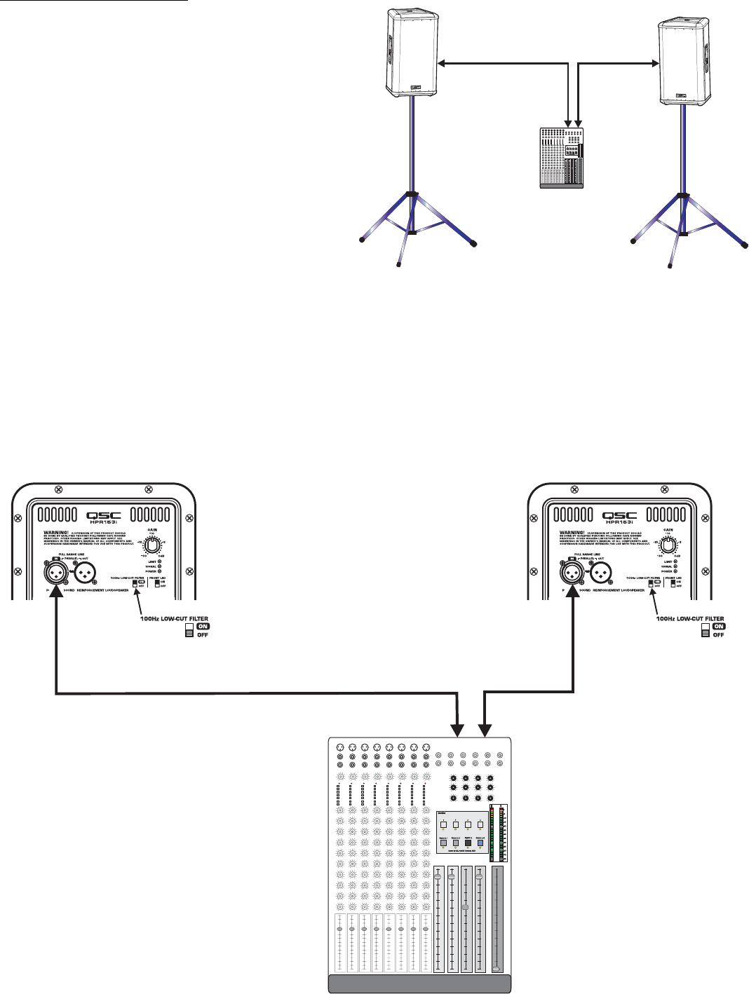
Application Example #1
This example shows a two-channel (stereo) setup utilizing two
top-boxes.
Audio signals for the Left and Right channels are supplied by
the mixer console. This signal source can be just about any
variable-output level audio source, such as DJ mixers, profes-
sional CD players, or computer-based audio signal sources.
Audio output from the mixer’s Left channel is connected to the
Left top-box’s FULL RANGE LINE IN connector. Audio output
from the mixer’s Right channel is connected to the Right top-
box’s FULL RANGE LINE IN connector. Turn off each top-box’s
100 Hz LOW-CUT FILTER. This will provide more low-frequency
content (bass) in the absence of a subwoofer.
Application Example #1 physical diagram.
HPR122i, HPR152i, or HPR153i
Mixer or Other Audio Source
Channel 1 or Left Channel Channel 2 or
Right Channel
Application Example #1 hookup diagram.
Use only high-quality balanced cables for
interconnecting the audio equipment.
Ensure the top-boxes have their 100 Hz LOW-
CUT FILTER switched OFF when using without
a subwoofer or other dedicated low-fre-
quency enclosure.
HPR122i, HPR152i, or HPR153i
15
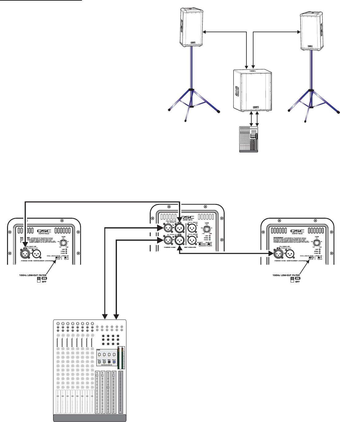
Application Example #2
This example shows a two-channel (stereo) setup utilizing one
subwoofer and two top-boxes.
Audio signals for the Left and Right channels are supplied by
the mixer console. This signal source can be just about any
variable-output level audio source, such as DJ mixers, profes-
sional CD players, or computer-based audio signal sources.
Audio output from the mixer is connected to the subwoofer’s
Left (L) and Right (R) channels. The subwoofer’s R and L FULL
RANGE LINE OUT connectors are used to connect to its respec-
tive top-box. Turn ON each top-box’s 100 Hz LOW-CUT FILTER.
Alternately, the top-boxes could be connected to the sub-
woofer’s 100 Hz LOW-CUT OUT and the top-boxes 100 Hz
LOW-CUT FILTERs turned off. The only possible issue with this
method of connection is unexpected noises (turn-off thumps) if
the subwoofer is powered up or down while the top boxes are
on. If connected as shown, power sequencing is not an issue.
Application Example #2 physical diagram.
Application Example #2 hookup diagram.
Use only high-quality balanced cables for inter-
connecting the audio equipment.
Ensure the top-boxes have their 100 Hz LOW-
CUT FILTER switched ON when connecting to
the subwoofer’s FULL RANGE LINE OUT as a sig-
nal source.
Also, be sure to keep Left and Right (marked L or
R) channels segregated properly so that sound-
stage imaging remains consistent.
HPR151i or HPR181i
Mixer or Other Audio Source
Channel 1 or
Left Channel Channel 2 or
Right Channel
HPR122i, HPR152i, or HPR153i HPR122i, HPR152i, or HPR153i
16
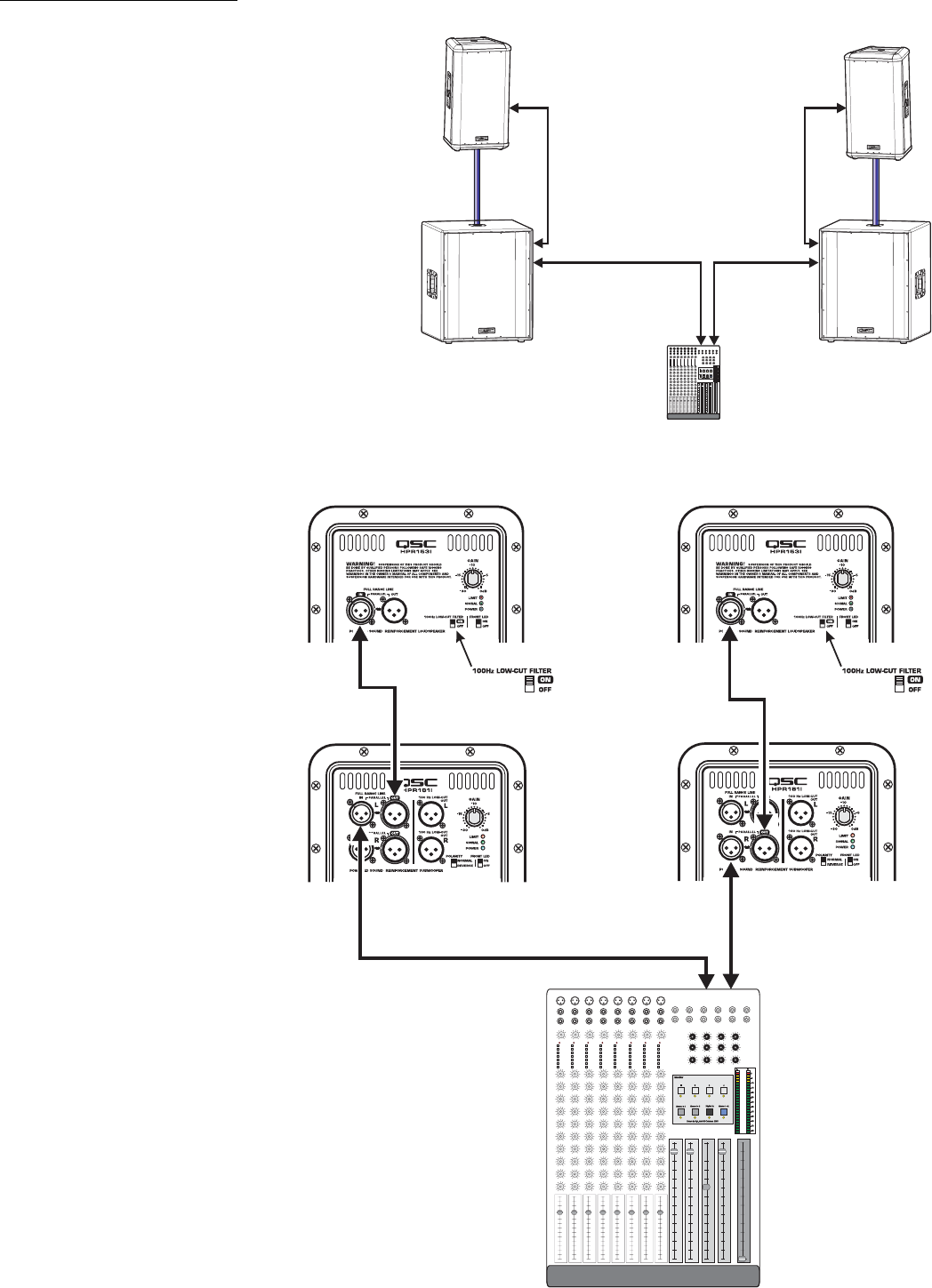
Application Example #3
This example shows a two-channel (stereo) setup utiliz-
ing two subwoofers and two top-boxes.
Audio signals for the Left and Right channels are supplied
by the mixer console. This signal source can be just about
any variable-output level audio source, such as DJ mix-
ers, professional CD players, or computer-based audio
signal sources.
Audio output from the mixer is connected to the sub-
woofer input of each channel. Each subwoofer’s FULL
RANGE LINE OUT connector is used to connect to its
respective top-box. Turn ON the top-box’s 100 Hz LOW-
CUT FILTER.
Alternately, the top-boxes could be connected to the sub-
woofer’s 100 Hz LOW-CUT OUT and the top-box 100 Hz
LOW-CUT FILTER turned off. The only possible issue with
this method of connection is unexpected noises (turn-off
thumps) if the subwoofer is powered down before the
top-boxes. If connected as shown, power sequencing is
not an issue.
Application Example #3 physical diagram.
Application Example #3 hookup diagram.
Use only high-quality balanced cables for
interconnecting the audio equipment.
Ensure the top-boxes have their 100 Hz LOW-
CUT FILTER switched ON when connecting
to the subwoofer’s FULL RANGE LINE OUT as
a signal source.
Also, be sure to use either the Left or Right
(marked L or R) on the subwoofers. If the
subwoofer’s input is connected to the Right
(R) channel connector and the output to the
top-boxes is connected to the Left (L) chan-
nel connector, no signal will reach the top-
box (no sound from the top-box).
Mixer or Other Audio Source
Channel 1 or Left Channel Channel 2 or Right
Channel
HPR122i, HPR152i, or HPR153i
HPR151i or HPR181i
17
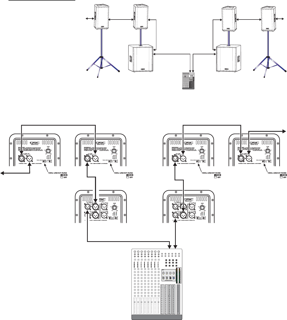
Application Example #4 hookup diagram.
Use only high-quality balanced cables for
interconnecting the audio equipment.
Ensure the top-boxes have their 100 Hz LOW-
CUT FILTER switched on when connecting to
the subwoofer’s FULL RANGE LINE OUT as a
signal source.
Also, be sure to use either the Left or Right
(marked L or R) on the subwoofers. If the sub-
woofer’s input is connected to the Right (R)
channel connector and the output to the top-
boxes is connected to the Left (L) channel
connector, no signal will reach the top-box
(no sound from the top-box).
Mixer or Other Audio Source
Channel 1
or
Left Channel
Channel 2
or
Right Channel
Application Example #4
This example shows a two-channel
(stereo) setup utilizing two sub-
woofers and multiple top-boxes.
This is the same as Application
Example #3 except an additional
top-box has been added to each
channel (and more could be added).
To connect to additional top-boxes,
connect a cable from the last top
box’s FULL RANGE LINE OUT con-
nector to the next top-box’s FULL
RANGE LINE IN connector. Up to 20
top-boxes could be “daisy-chained”
without degrading signal quality.
HPR151i or HPR181i
HPR122i, HPR152i, or HPR153i HPR122i, HPR152i, or HPR153i
Application Example #4 physical diagram.
18
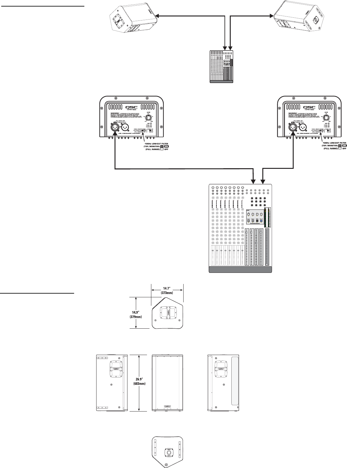
Application Example #5
This example shows a two-chan-
nel (stereo) setup utilizing two
HPR122i loudspeakers as floor
monitors.
Audio signals for the Left and
Right channels are supplied by the
mixer console auxiliary buss. This
allows the monitor level to be
adjusted independently from the
main (house) mix.
Audio output from the mixer’s Left
auxiliary buss is connected to the
Left top-box’s FULL RANGE LINE
IN connector. Audio output from
the mixer’s Right auxiliary buss is
connected to the Right floor moni-
tor’s FULL RANGE LINE IN connec-
tor. Turn ON each monitor’s 100 Hz
LOW-CUT FILTER. This will
improve vocal clarity and minimize
low frequency (bass) buildup on
stage.
Application Example #5 physical diagram.
HPR122i
Mixer or Other Audio Source
Channel 1
or
Left Channel
Channel 2
or
Right Channel
Application Example #5 hookup diagram.
Use only high-quality balanced cables for
interconnecting the audio equipment.
Ensure the floor-monitors have their 100 Hz
LOW-CUT FILTER switched ON to provide
improved clarity in the middle- and high- fre-
quencies. This also reduces bass build-up on
stage.
HPR122i
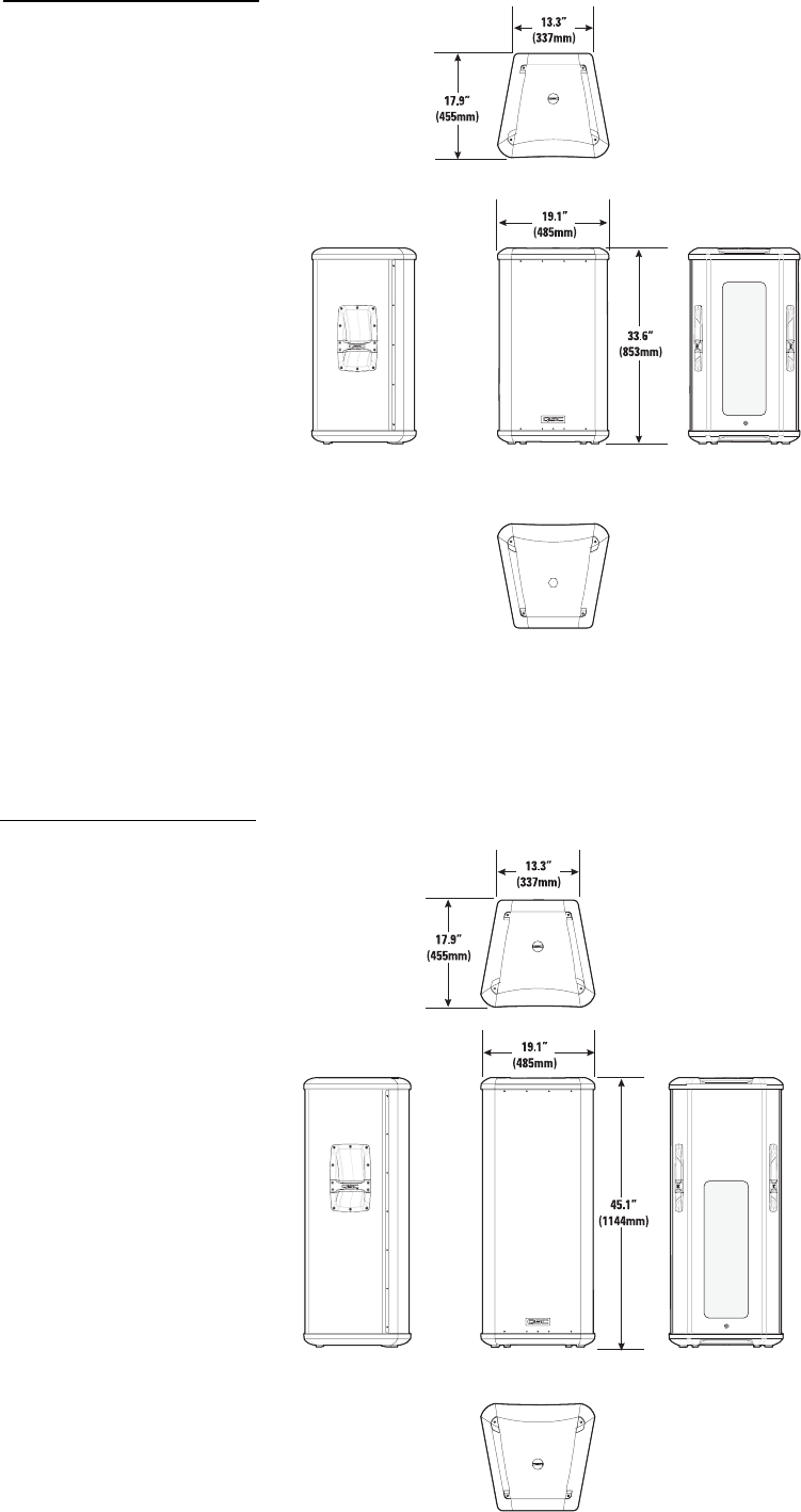
Dimensions, HPR122i
19
Dimensions, HPR152i
Dimensions, HPR153i
20
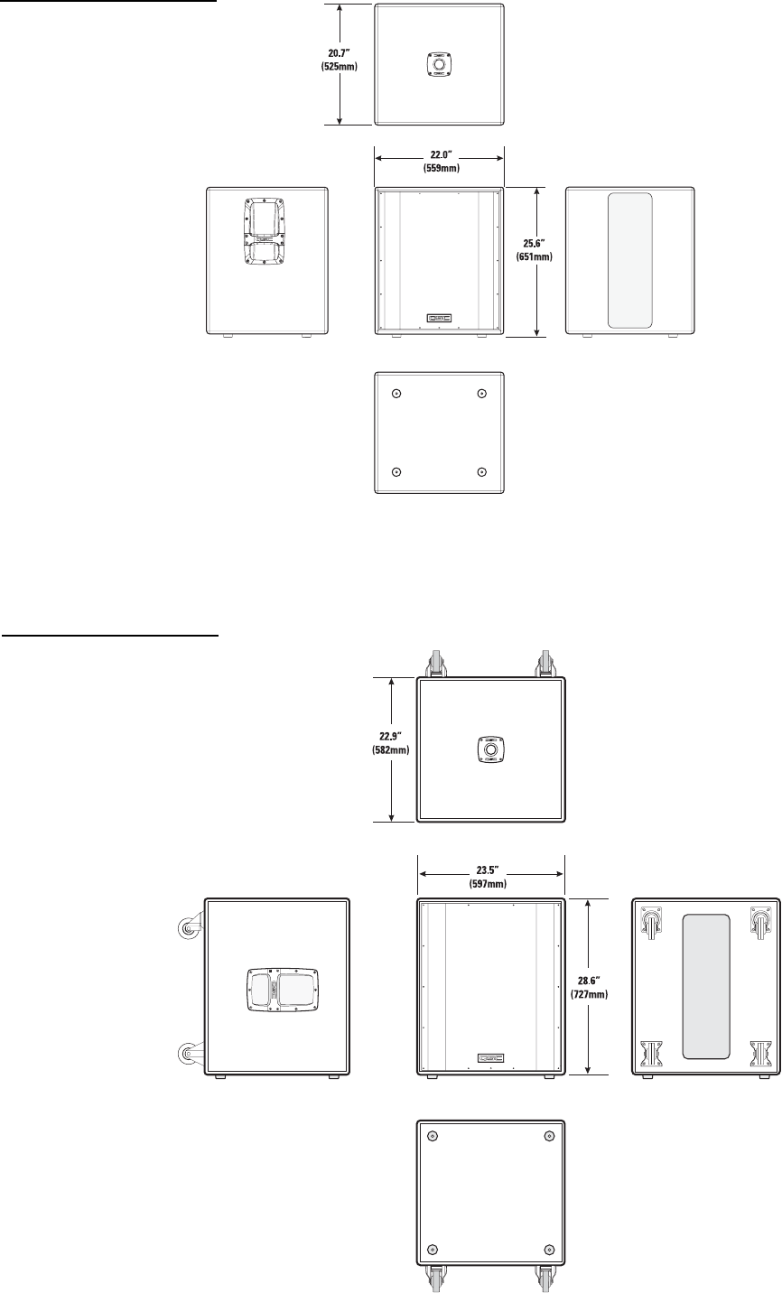
Dimensions, HPR151i
Dimensions, HPR181i

21
Specifications, HPR122i HPR122i
Frequency Response, -3dB 62-18k Hz
Frequency Range, -10dB 53-22k Hz
Maximum Peak SPL 131dB
Nominal coverage, H x V 75°x75°
Directivity Index 9.7
Directivity Factor 9.4
Transducer Description 12” (309mm) transducer with 3” (76mm) voice coil
1” (25mm) throat compression drive
Acoustic Crossover Freq. 2,000 Hz
Amp Power 400 Watts, low frequency
100 Watts, high frequency
Input Sensitivity 0.775 Vrms (+0dBu)
Input Headroom/Clipping 10 Vrms (+22.2dBu)
Input Connector/Impedance XLR female, 22k Ohm, balanced, line-level input
(unbalanced, 11k Ohm)
Output Connector XLR male, wired in parallel with Input connector
Controls, Indicators, and Gain control, 100 Hz low-cut filter switch, Front LED on/off switch, Limit/Clip (red LED), Signal presence (green LED), AC Power (blue LED),
Adjustments AC Power switch, AC circuit breaker
Protection, Agency certs. Thermal limiting, On/Off muting, power limiting, DC protection, short circuit protection, ultrasonic protection, RF protection, UL/CE listed
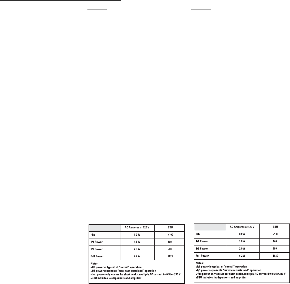
AC Power Requirements
AC Power Connector and Cordset Factory supplied IEC cordset: 9’ (3m) #18AWG 120V North American or European 230V cordset
Dimensions (height, width, depth) 26.9” (683mm) x 14.7” (373mm) x 14.9” (379mm)
Installation Clearance Allow for 6.0” (152mm) of free space behind the enclosure to assure proper amplifier cooling
Weight 60 lb/27.2 kg
Finish and Grill Wear-resistant textured paint finish on plywood enclosure and powder-coated perforated steel grill
Notes:
1- Maximum Peak SPL: Calculated by adding the loudspeaker’s sensitivity (1W at 1m) to the peak power (dBw) of the amplifier provided.
2- Directivity Index (DI): Difference between on-axis SPL and average SPL (considering all axes) for the specified coverage range. DI= 10 log Q
3- Directivity Factor (Q): Directivity index expressed as a power ratio Q=10 exp DI/10
4- Amplifier Power: The maximum sustained power at less than 1% clipping, averaged over the intended frequency range,
5- Input Sensitivity: The sine-wave input voltage required to reach amplifier clipping, measured within the frequency range used to determine Maximum Peak SPL, with the gain on “normal” and no gain reduction
due to limiting.
6- Input Headroom/Clipping: Maximum input voltage.
7- Input Connector/Impedance: RF shunt capacitance should not reduce impedance by more than 30% at 20k Hz.
22
Specifications, HPR152i and HPR153i
HPR152i HPR153i
Frequency Response, -3dB 54-17.5k Hz 41-17.5k Hz
Frequency Range, -10dB 47-20k Hz 36-20k Hz
Maximum Peak SPL 135dB 133dB
Nominal coverage, H x V 90°x60° 90°x40°
Directivity Index 9.4 11.1
Directivity Factor 8.7 12.9
Transducer Description 15” (381mm) transducer with 3” (76mm) voice coil 15” (381mm) transducer with 3” (76mm) voice coil
1” (25mm) throat compression driver 6.5” (165mm) transducer with 1” (25mm) voice coil
1” (25mm) throat compression driver
Acoustic Crossover Freq. 2,000 Hz 500 and 2,000 Hz
Amp Power 400 Watts, low frequency 400 Watts, low frequency
100 Watts, high frequency 100 Watts, mid frequency
100 Watts, high frequency
Input Sensitivity 0.775 Vrms (+0dBu) 0.775 Vrms (+0dBu)
Input Headroom/Clipping 10 Vrms (+22.2dBu) 10 Vrms (+22.2dBu)
Input Connector/Impedance XLR female, 22k Ohm, balanced, line-level input XLR female, 22k Ohm, balanced, line-level input
(unbalanced, 11k Ohm) (unbalanced, 11k Ohm)
Output Connector XLR male, wired in parallel with Input connector XLR male, wired in parallel with Input connector
Controls, Indicators, and Gain control, 100 Hz low-cut filter switch, Front LED on/off switch, Limit/Clip (red LED), Signal presence (green LED), AC Power (blue LED),
Adjustments AC Power switch, AC circuit breaker
Protection, Agency certs. Thermal limiting, On/Off muting, power limiting, DC protection, short circuit protection, ultrasonic protection, RF protection, UL/CE listed
AC Power Requirements
AC Power Connector and Cordset Factory supplied IEC cordset: 9’ (3m) #18AWG 120V North American or European 230V cordset
Dimensions (height, width, depth) 33.6” (853mm) x 19.1” (485mm) x 17.9” (455mm) 45.1” (1144mm) x 19.1” (485mm) x 17.9” (455mm)
Installation Clearance Allow for 6.0” (152mm) of free space behind the enclosure to assure proper amplifier cooling
Weight 100 lb/45.4 kg 118 lb/53.5 kg
Finish and Grill Wear-resistant textured paint finish on plywood enclosure and powder-coated perforated steel grill
Notes:
1- Maximum Peak SPL: Calculated by adding the loudspeaker’s sensitivity (1W at 1m) to the peak power (dBw) of the amplifier provided.
2- Directivity Index (DI): Difference between on-axis SPL and average SPL (considering all axes) for the specified coverage range. DI= 10 log Q
3- Directivity Factor (Q): Directivity index expressed as a power ratio Q=10 exp DI/10
4- Amplifier Power: The maximum sustained power at less than 1% clipping, averaged over the intended frequency range,
5- Input Sensitivity: The sine-wave input voltage required to reach amplifier clipping, measured within the frequency range used to determine Maximum Peak SPL, with the gain on “normal” and no gain reduction
due to limiting.
6- Input Headroom/Clipping: Maximum input voltage.
7- Input Connector/Impedance: RF shunt capacitance should not reduce impedance by more than 30% at 20k Hz.
23
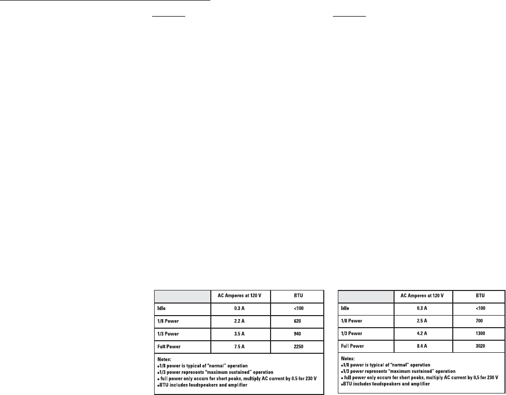
Specifications, HPR151i and HPR181i
HPR151i HPR181i
Frequency Response, -3dB 51-105 Hz 45-95 Hz
Frequency Range, -10dB 43-145 Hz 39-145 Hz
Maximum Peak SPL 133dB 134dB
Nominal coverage, H x V Not applicable (N/A) Not applicable (N/A)
Transducer Description 15” (381mm) transducer with 3” (76mm) voice coil 18” (457mm) transducer with 4” (102mm) voice coil
Amp Power 700 Watts 700 Watts
Input Sensitivity 0.775 Vrms (+0dBu) 0.775 Vrms (+0dBu)
Input Headroom/Clipping 10 Vrms (+22.2dBu) 10 Vrms (+22.2dBu)
Input Connectors/Impedance Two XLR female, 22k Ohm, balanced, left and right (L+R) inputs (11k Ohms unbalanced)
Output Connectors Four XLR male: two wired in parallel with Input connector (full range), two post-100 Hz low-cut filters
Controls, Indicators, and Gain control, Polarity switch (normal/reverse), Front LED on/off switch, Limit/Clip (red LED), Signal presence (green LED), AC Power (blue LED)
Adjustments AC Power switch, AC circuit breaker
Protection, Agency certs. Thermal limiting, On/Off muting, power limiting, DC protection, short circuit protection, ultrasonic protection, RF protection, UL/CE listed
AC Power Requirements
AC Power Connector and Cordset Factory supplied IEC cordset: 9’ (3m) #18AWG 120V North American or European 230V cordset
Dimensions 25.6” (651mm) x 22” (559mm) x 20.7” (525mm) 28.6” (727mm) x 23.5” (597mm) x 22.9” (582mm)
Weight 98 lb/44.5 kg 127 lb/57.6 kg
Finish and Grill Wear-resistant textured paint finish with powder-coated perforated steel grill
Notes:
1- Maximum Peak SPL: Calculated by adding the loudspeaker’s sensitivity (1W at 1m) to the peak power (dBw) of the amplifier provided.
2- Directivity Index (DI): Difference between on-axis SPL and average SPL (considering all axes) for the specified coverage range. DI= 10 log Q
3- Directivity Factor (Q): Directivity index expressed as a power ratio Q=10 exp DI/10
4- Amplifier Power: The maximum sustained power at less than 1% clipping, averaged over the intended frequency range,
5- Input Sensitivity: The sine-wave input voltage required to reach amplifier clipping, measured within the frequency range used to determine Maximum Peak SPL, with the gain on “normal” and no gain reduction due to
limiting.
6- Input Headroom/Clipping: Maximum input voltage.
7- Input Connector/Impedance: RF shunt capacitance should not reduce impedance by more than 30% at 20k Hz.

Warranty (USA only; other countries, see your dealer or distributor)
Disclaimer
QSC Audio Products, Inc. is not liable for any damage to amplifiers or any other equipment that is caused
by negligence or improper installation and/or use of this loudspeaker product.
QSC Audio Products 3 Year Limited Warranty
QSC Audio Products, Inc. (“QSC”) guarantees its products to be free from defective material and / or
workmanship for a period of three (3) years from date of sale, and will replace defective parts and repair
malfunctioning products under this warranty when the defect occurs under normal installation and use -
provided the unit is returned to our factory or one of our authorized service stations via prepaid transpor-
tation with a copy of proof of purchase (i.e., sales receipt). This warranty provides that the examination
of the return product must indicate, in our judgment, a manufacturing defect. This warranty does not
extend to any product which has been subjected to misuse, neglect, accident, improper installation, or
where the date code has been removed or defaced. QSC shall not be liable for incidental and/or conse-
quential damages. This warranty gives you specific legal rights. This limited warranty is freely transfer-
able during the term of the warranty period.
Customer may have additional rights, which vary from state to state.
In the event that this product was manufactured for export and sale outside of the United States or its
territories, then this limited warranty shall not apply. Removal of the serial number on this product, or
purchase of this product from an unauthorized dealer, will void this limited warranty.
Periodically, this warranty is updated. To obtain the most recent version of QSC’s warranty statement,
please visit www.qscaudio.com.
Contact us at 800-854-4079 or visit our website at www.qscaudio.com
1675 MacArthur Blvd., Costa Mesa, CA, 92626 USA
Main Number (714) 754-6175 or toll free (USA only) (800) 854-4079
Customer Service(714) 957-7150 or toll free (USA only) (800) 772-2834
© Copyright 2006, QSC Audio Products, Inc.
QSC® is a registered trademark of QSC Audio Products, Inc.
“QSC” and the QSC logo are registered with the U.S. Patent and Trademark Office
All trademarks are the property of their respective owners.
