Quake Global 96XXCS Q4000 / QPRO Satellite Module User Manual Datasheet QPRO
Quake Global Inc. Q4000 / QPRO Satellite Module Datasheet QPRO
UserManual.wiki
>
Quake Global
>
96XXCS User Manual
>
Datasheet QPRO
Contents
1.
Datasheet QPRO
2.
Full Manual part 2
3.
Full Manual part 3
4.
Full Manual part 5
5.
Full Manual part 7
6.
Datasheet Q4000
7.
Full Manual part 1
8.
Full Manual part 4
9.
Full Manual part 6
Datasheet QPRO
Navigation menu
Upload a User Manual
Namespaces
Wiki Guide
HTML
PDF
Info
Views
User Manual
Discussion / Help
Navigation
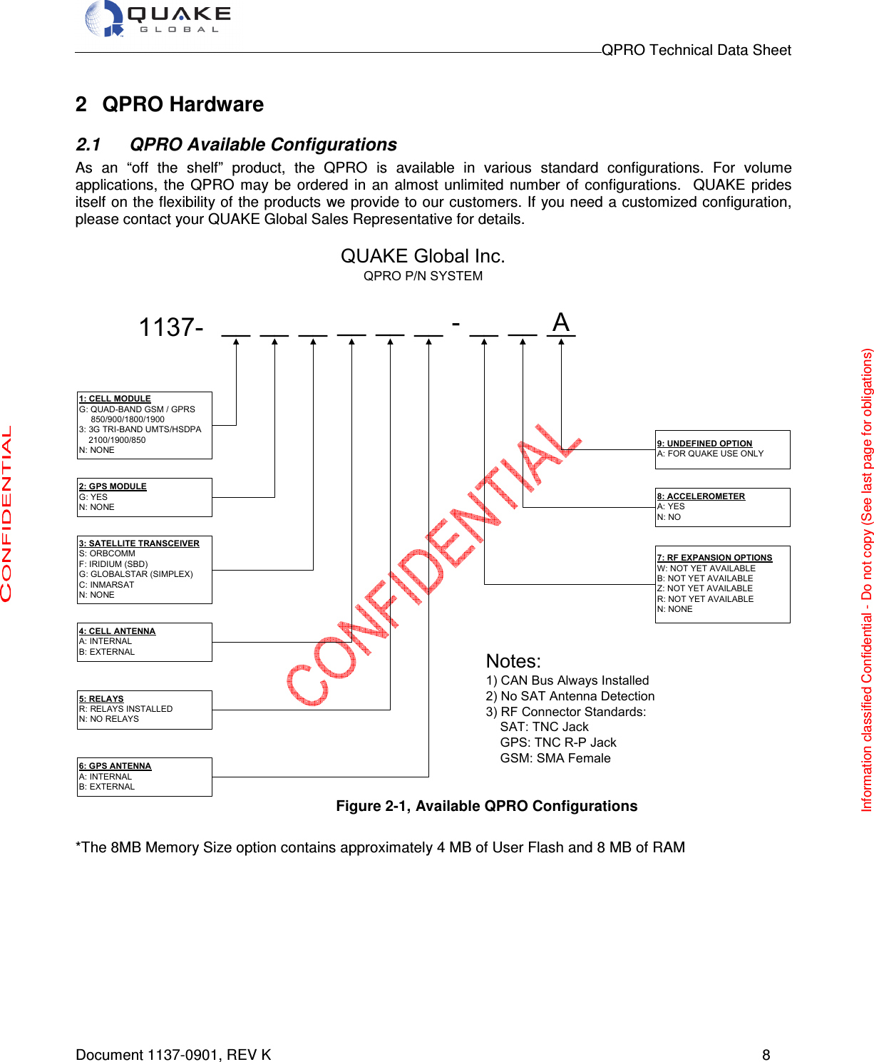
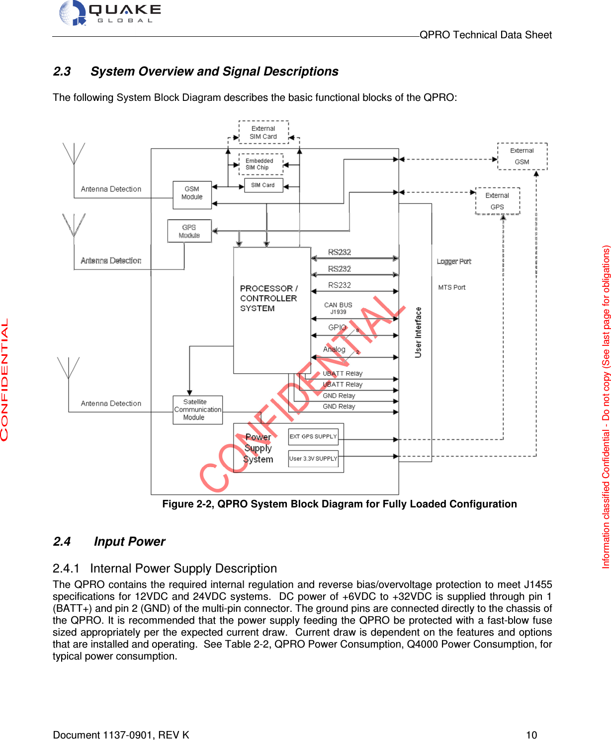
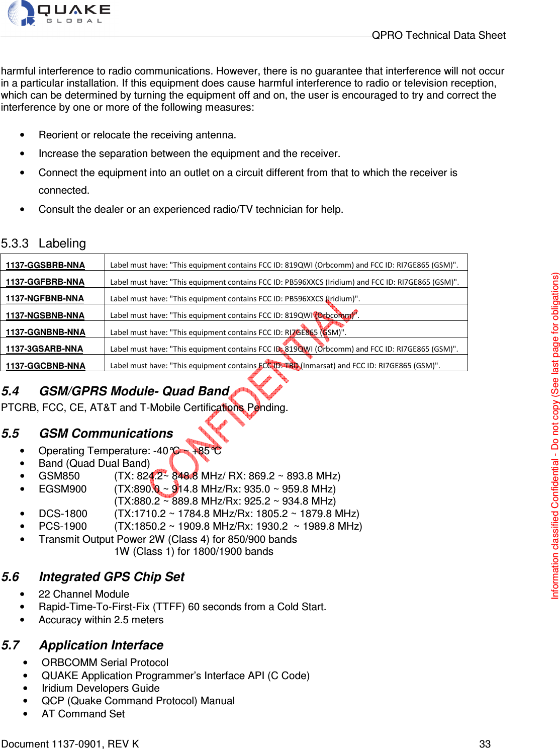
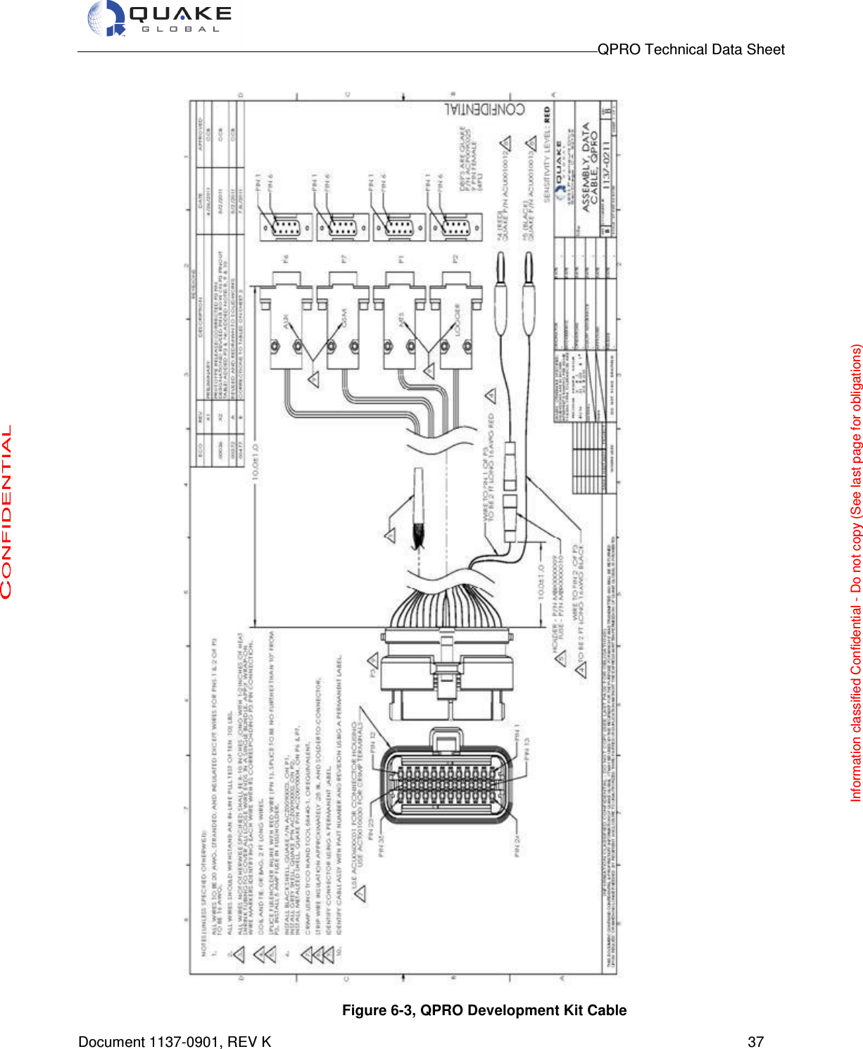
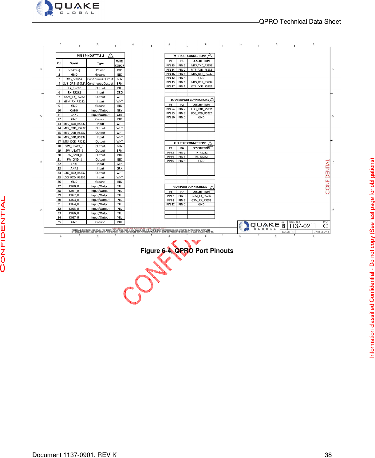
![QPRO Technical Data Sheet Document 1137-0901, REV K 31 5 QPRO Data Interface Specifications 5.1 Data Interfaces • 4 Digital Output Switches (2 Switched GND/2 Switched Input Power Voltage) • 8 Digital General Purpose Inputs/Outputs (CMOS level 3.5VDC) • 3 Serial Ports (External) Up to 4 RS-232 ports depending on QPRO configuration • 1 CAN BUS 2.0: J1850/1939 • 2 Analog Inputs (0 – 3.5 V) Note: The auxiliary port is not available for customer use on QPRO models that include an Iridium or Inmarsat satellite option 5.2 Environmental Considerations The QPRO has been specifically designed for harsh environments. As an OEM product, it is housed in an IP-67 rated enclosure. • Operating Temperature o –40C to 85C • Storage Temperature o –50C to 85C. • Low Pressure o Up to 4 hours at 15000 ft elevation pressure • Humidity o Relative humidity range of 0% to 95% non-condensing at 65C o Humidity Test in ORBCOMM Spec E25050102 REV D is per MIL SPEC 810E, Method 507.3 with test conditions. Procedure I, Cycle 2 Procedure 1 simulates natural environmental cycles and it is conducted on test items which are open to the environment of frequently ventilated, Cycle 2 set temperature at 24 deg C constant with humidity maintained at 95% minimum. Test Duration: 15 Cycles (15 days ) • Cyclic Humidity o Temperature/Cyclic Humidity Test, 5 days at -10C to 65C at 85% relative humidity • Thermal Shock o -40C to 85C (30 minutes at each temp, 10 cycles) • Shock o Mechanical shock of a 20G, saw tooth profile, over an 11 msec period. (Three positive and three negative shocks in each of three mutually perpendicular axes) o SAEJ1455 shock requirements and those in MIL-STD-810E [11]. • Vibration o 20 Hz to 2 KHz, 8 Grms vibration profile in each of three mutually perpendicular axes, 1 hour per axis, o 10 Hz to 150 HZ, 0.5 g square/Hz vibration profile in each of three mutually perpendicular axes, 1 hour per axis. o 10 Hz to 150 HZ, 0.05 g^2/Hz vibration, 16 hours on each of three orthogonal axis o 5 Hz to 20 Hz , 0.05 g^2/hz, and from 20 to 150 Hz, -3 dB/octave, 1 hour each axes Information classified Confidential - Do not copy (See last page for obligations)](https://usermanual.wiki/Quake-Global/96XXCS.Datasheet-QPRO/User-Guide-1626620-Page-31.png)
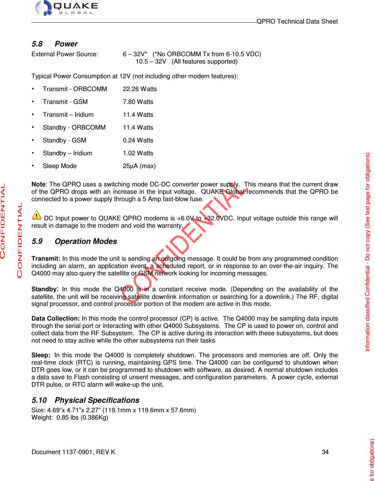
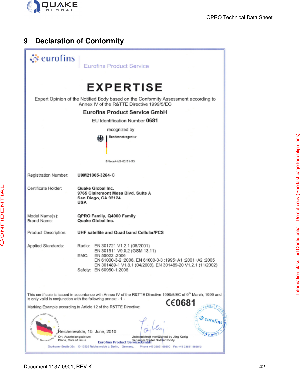
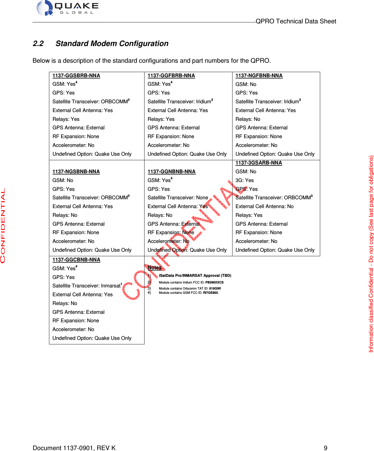
![QPRO Technical Data Sheet Document 1137-0901, REV K 32 o Vibration requirements in ORBCOMM Rev D spec [10] and MIL-STD-810E [11] o SAEJ1455 vibration requirements. 5.3 Certifications • ORBCOMM Type Approval pending • Iridium Certification pending • FCC • CE • J1939 compliance • J1455 • IP67 water submersion This device complies with Industry Canada licence-exempt RSS standard(s). Operation is subject to the following two conditions: (1) this device may not cause interference, and (2) this device must accept any interference, including interference that may cause undesired operation of the device. Le présent appareil est conforme aux CNR d'Industrie Canada applicables aux appareils radio exempts de licence. L'exploitation est autorisée aux deux conditions suivantes : (1) l'appareil ne doit pas produire de brouillage, et (2) l'utilisateur de l'appareil doit accepter tout brouillage radioélectrique subi, même si le brouillage est susceptible d'en compromettre le fonctionnement. This device complies with Part 15 of the FCC Rules. Operation is subject to the following two conditions: (1) this device may not cause harmful interference, and (2) this device must accept any interference received, Including interference that may cause undesired operation. Note: Any changes or modifications to the QPRO product could avoid the final operation of equipment and will void Quake Global’s warranty. 5.3.1 FCC IDs One of the following FCC ID’s will apply, depending on the modem network type (see standard modem configurations for details on which part numbers contain which approvals): • iSatData Pro/Inmarsat Approval (TBD) • Iridium FCC ID: PB596XXCS • Orbcomm TAT ID: 819QWI • GSM FCC ID: RI7GE865. 5.3.2 FCC Part 15 Class B - Radio Frequency Interference (RFI) (FCC 15.105) This equipment has been tested and found to comply with the limits for Class B digital devices pursuant to Part 15, Subpart B of the FCC Rules. These limits are designed to provide reasonable protection against harmful interference in a residential environment. This equipment generates, uses, and can radiate radio frequency energy, and if not installed and used in accordance with the instruction manual, may cause](https://usermanual.wiki/Quake-Global/96XXCS.Datasheet-QPRO/User-Guide-1626620-Page-32.png)