Qual Tron QTIMIDSMBMCDT MCDT TRANSMITTER User Manual
Qual-Tron, Inc. MCDT TRANSMITTER Users Manual
Users Manual

QTI Page 1 of 15 Revision: D
Form #: 30Z0250 Effective Date: 1 August 2010
9409 E. 55th Pl. S. • Tulsa, OK 74145 • Ph: (918) 622-7052 • Fax: (918) 664-8557
M
MC
CD
DT
T
I
IN
NS
ST
TR
RU
UC
CT
TI
IO
ON
N
M
MA
AN
NU
UA
AL
L
MCDT Multi-Channel Data Transceiver
P/N 10D1067
All rights reserved. No part of this book may be reproduced or utilized in any form or by any means,
electronic or mechanical, without the prior written permission of Qual-Tron, Inc.

QTI Page 2 of 15 Revision: D
Form #: 30Z0250 Effective Date: 1 August 2010
MCDT Instruction Manual
Table of Contents
Section 1: MCDT Multi-Channel Data Transceiver ............................................................ 3
Description .................................................................................................................................................. 3
Model Numbers (9 models) ......................................................................................................................... 3
Design Features ........................................................................................................................................... 4
Physical Characteristics ............................................................................................................................... 4
Section 2: MCDT Operation ................................................................................................... 6
Receiving/Transmitting ............................................................................................................................... 6
ITEMS REQUIRED ................................................................................................................................ 6
SETUP ..................................................................................................................................................... 6
RF Link ........................................................................................................................................................ 6
Section 3: Serial Interface ....................................................................................................... 7
Message Serial Format ................................................................................................................................ 7
Command List ............................................................................................................................................. 9
CHECKSUM: .............................................................................................................................................. 13
Section 4: Maintenance ........................................................................................................... 14
OPERATOR MAINTENANCE: ............................................................................................................. 14
DEPOT MAINTENANCE: ..................................................................................................................... 14
EQUIPMENT STORAGE: ...................................................................................................................... 14
WARRANTY: ......................................................................................................................................... 14
RETURN PROCEDURES: ..................................................................................................................... 14
TROUBLESHOOTING GUIDE: ............................................................................................................ 14
Section 5: Frequency/Channel Calculations ......................................................................... 15
Channel to Frequency Calculation .............................................................................................................. 15
Frequency to Channel Calculation .............................................................................................................. 15
Section 6: FCC RF Exposure Limits ..................................................................................... 15
HISTORY
Revision Changes Date
O/I Original Issue 04/13/2009
A General Corrections 03/02/2010
B General Corrections 04/08/2010
C New shields; different connector pin outs for Receiver/Transmitter
differences.
Removed battery references in “Equipment Storage” in Section 4
06/17/2010
D Added model numbers. Corrected the description of pins 4 & 5 on the
RS485 connection to match RS-485 standards. Pin 4 is B+ and Pin 5 is A-
Added RS-485 schematic. Added “CMB” and “PSH 2” commands.
8/01/2010
QTI Page 3 of 15 Revision: D
Form #: 30Z0250 Effective Date: 1 August 2010
Section 1: MCDT Multi-Channel Data Transceiver
Description
The Multi-Channel Data Transceiver (MCDT) is an OEM modular modem for users who need low-
power and small size with serial communications. The MCDT can be constructed as a transmitter, a
receiver or as a transceiver. The MCDT is equipped with a RS-485 communications port which is a
simple, low-cost interface, utilizing few components and allows for daisy-chaining multiple receivers.
The MCDT is capable of transmitting or receiving SEIWG-005 data messages which includes a
distinct ID and a status code, over a selectable frequency range. This frequency is selectable via the
synthesizer control circuit, providing a selection of up to 1920 RF channels, depending on the model’s
frequency range. The MCDT comes in Low-Band, Mid-Band, and High-Band models, having the
following frequency ranges:
Low Band Medium Band High Band
Channel 001 = 138.025 MHz Channel 001 = 154.005 MHz Channel 001 = 162.00625 MHz
Channel 600 = 153.000 MHz Channel 1600 = 162.000 MHz Channel 1920 = 174.000 MHz
Channel Spacing: 25 kHz Channel Spacing: 5 kHz Channel Spacing: 6.25 kHz
Model Numbers (9 models)
10D1067-RL, -RM, -RH MCDT Receiver only, low, mid, or high band
10D1067-TL, -TM, -TH MCDT Transmitter only, low, mid, or high band
10D1067-XL, -XM, -XH MCDT Transceiver, low, mid, or high band
Antenna: MMCX plug 50 ohm (J1)
(10D1984 MMCX to TNC 3” cable available)
Power Supply:
4.0 VDC to 16.5 VDC nominal
4.0 VDC to 16.5 VDC 1W Transmit
4.4 VDC to 16.5 VDC 2W Transmit
3.5 VDC to 16.5 VDC Receive
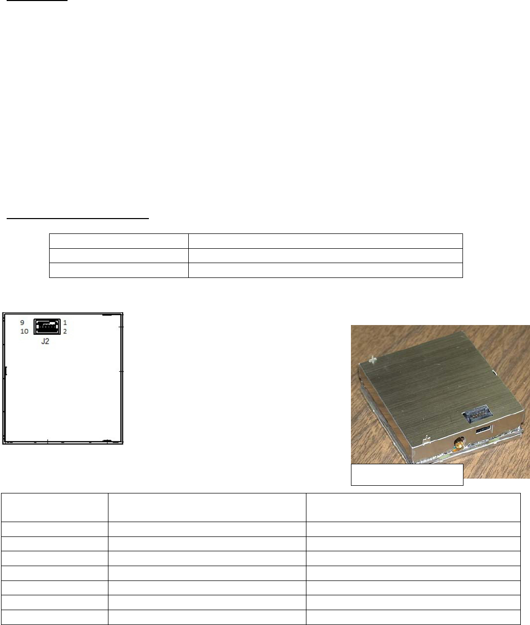
Connections:
J2 - Header Pin
(10-pin TFM-105) Receiver Only Function Transmitter & Transceiver Function
1, 2 Vin [Input] 3.5 to 16.5 VDC Vin [Input] 4.0 to 16.5 VDC
3 Not Used Transmit Drive [Output] Active low
4 RS485 – B(+) [I/O] RS485 – B(+) [I/O]
5 RS485 – A(-) [I/O] RS485 – A(-) [I/O]
6 Same as pins 1,2 VCC [Out] 5.4VDC 50mA/3A
7 General I/O General I/O
8, 9, 10 GND GND
MCDT Receiver
QTI Page 4 of 15 Revision: D
Form #: 30Z0250 Effective Date: 1 August 2010
Current Draw Approximations:
Mode Current Comments
Sleep 20uA MCDT wakes up on RS485 bus activity
Active 5.0mA Receiver Off / Microprocessor On
Transmission(1Watt) 57ms @ 1.5A Pulse Current Provided by Super Caps
Transmission(2Watt) 57ms @ 3A Pulse Current Provided by Super Caps
Receiver On 11 to 12.6mA Receiver On – Waiting for valid RF message
Receiver Active 16.9mA RF message received – Microprocessor On
Design Features
ID Code Selection 000-999 for EMIDS, 000-063 for all other formats
Directional, sensor fault, low battery, tamper, and test status codes for EMIDS format
Able to receive and transmit MIDS 20-bit or MMIDS / EMIDS 29-bit messages
MMCX antenna port matched to 50 ohms
Conformal-coated and shielded circuit assembly
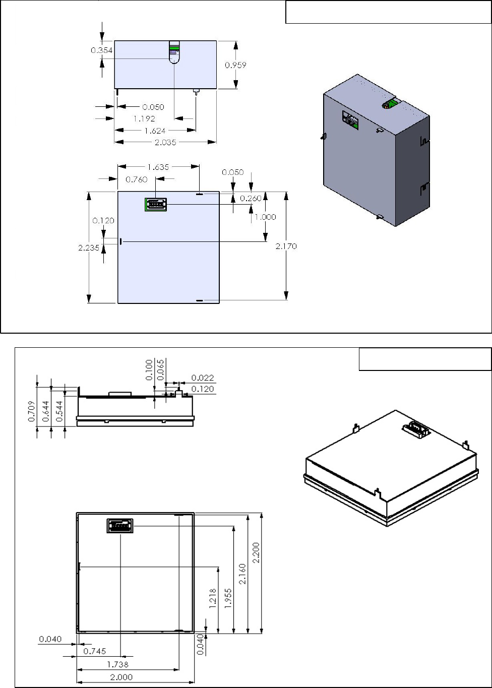
Physical Characteristics
The MCDT is light weight and comes in a compact size. This makes it ideal for mobile applications as
well as applications with tight space constraints.
Receiver Only Transmitter Only Transceiver
Weight 62 g (2.2 oz) 89 g (3.1oz) 104 g (3.7oz)
Height 1.38 cm (0.544 in) 2.36 cm (0.929 in)
Length 5.60 cm (2.206 in)
Width 5.10 cm (2.006 in)
The shielding on the MCDT has been designed in a way to promote easy PCB integration. The top of
the MCDT is equipped with three alignment tabs that can be used as standoffs. The alignment tabs are
delivered down on the transmitter and can be bent upward if needed. By utilizing these pins and a
proper connector you are able to design a board that connects to the MCDT. Dimensions for the
transmitter, transceiver and receiver MCDTs are shown in figures 1 & 2 below. The receiver MCDT
has identical dimensions except for height.
Connections to the MCDT can be made by connecting to the J2 header. The header as used on the
MCDT is SAMTEC part TFM-105-XX-X-D. The recommended mate is SFM-105-T2-L-D-P from
SAMTEC. These are 2 x 5 pin headers with a 50 mil pitch. See Connections table above to determine
pin outs.
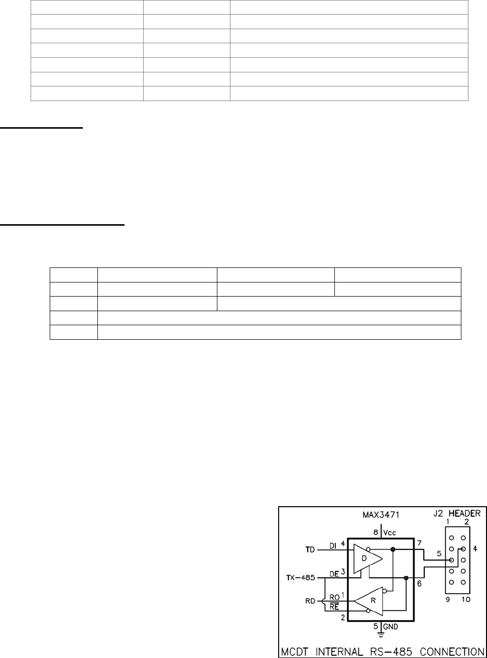
The serial RS485 I/O driver IC used by Qual-tron is a
MAXIM part. The part number is MAX3471EUA+. If
the customer also includes this IC from MAXIM in
their design, connect pin 6 of the IC to pin 4 on J2 and
connect pin 7 to pin 5 on J2. Note: Sometimes RS485
devices are marked with the polarity reversed from
normal RS485 standards. If a new or unknown device
cannot communicate, try reversing the differential lines
usually marked A & B.
QTI Page 5 of 15 Revision: D
Form #: 30Z0250 Effective Date: 1 August 2010
Fig. 1 MCDT Transmitter/Transceiver
Fig. 2 MCDT Receiver

QTI Page 6 of 15 Revision: D
Form #: 30Z0250 Effective Date: 1 August 2010
Section 2: MCDT Operation
Using the settings provided in Section 3: Serial Interface, open a serial communication program such
as HyperTerminal and supply power to the MCDT. A USB to RS485 cable is available that can
connect directly to the MCDT. The USB port from a computer is capable of powering the “receiver
only” version. However, it is not recommended that the MCDT “transmitter only” and transceiver units
be powered from the USB port. The current draw during the initial super-capacitor charging period and
during transmission may cause damage to the cable and/or computer.
Start Up
When the MCDT is initially powered on, a “BL<CR>” output string is sent to indicate the opportunity
for entering the “Boot Loader” mode. The ability to enter the boot loader mode will timeout after 1
second.
The next serial output that is sent after the BL timeout is the reason for the reset or restart. It can be
one of the following messages: "PWR-ON RST", "EXT RST PIN", "COP RST", "ILLEGAL OP
RST", "ICG RST", "LVD RST", or "UNKNOWN RST".
After the reset message, the version information is sent “MCDT 028A 003G<CR>” for example. (See
the VER command for the description).
NOTE: The “BL” (Boot Loader) response provides the opportunity to enter the programming mode for
one (1) second at start up. Sending a “P” (no “<CR>”) will enter the firmware upgrade mode and
could cause the firmware to be erased. Therefore, the user is advised not to send any characters to the
unit, especially not a character “P” followed by a character “Y” to the MCDT before the version
information is received.
Receiving/Transmitting
During normal operation, the MCDT is capable of sending and receiving SEIWG-005 messages via the
serial port and via radio frequency. The MCDT assumes a low-power shut-down mode to conserve
power when not in use.
ITEMS REQUIRED
1. DC Power Source: 4.0 to 16.5 Volts
2. Personal Computer with USB or RS232 port
3. 10-pin connector to RS-485 USB cable (QTI part# 10D1978)
4. Serial Communications Program such as HyperTerminal
SETUP
1. Set the Channel. (Default CHR 001)
2. Enable receiver, if desired. Transmit is always enabled. (Default RCV 1)
3. Enable Push to send messages out serial port, or disable to poll for messages. (Default PSH 1)
RF Link
The operational range of the RF link is dependent upon various conditions. The high frequency of the
RF link works best under line of sight conditions. RF range may vary from 0.5 kilometer to 5
kilometers for open areas using the 1-Watt setting. Greater range may be expected using the 2-Watt
setting.

QTI Page 7 of 15 Revision: D
Form #: 30Z0250 Effective Date: 1 August 2010
NOTE: Elevating an antenna will increase transmission and/or reception range significantly. The use
of relays/repeaters can also be used to increase transmission ranges. Also transmitting and receiving
antennas should both point in the same direction (typically up) so they have the same polarization.
Section 3: Serial Interface
The MCDT defaults to a low-power shut down mode with the receiver still operating (if installed). If
push is enabled (“PSH 1”), the MCDT will send the message via the serial port upon receiving an RF
message, and then return to shut-down immediately. The user may initiate serial communication by
sending the MCDT two carriage returns. This is to allow the MCDT time to wake-up from the power-
down mode. After 1 minute of inactivity on the serial port, the MCDT returns to low-power shut down
mode. If the user has disabled the PUSH setting (“PSH 0”), and a new message is received, the MCDT
will send its RS485 ID. See the SID command. This is used to wake-up the user’s application
processor. Once awake the user can poll to get the new message. See the NEW command. If the
MCDT is still awake and the MCDT receives a new message, the shut-down mode will not occur until
the RS485 serial ID has been sent and acknowledged. The user’s application must respond or an
infinite loop condition would occur causing the MCDT to never shut-down.
The MCDT communicates over RS-485. Commands must be followed by a carriage return (<CR>).
Settings are retained only until power is turned off unless the SAV command is used to store them to
the unit’s flash memory. When sending commands and queries, a two-digit hexadecimal checksum
(cs) can be used to check data integrity, refer to Checksum section after command list.
SETTINGS
38400 baud [fixed], No parity, 8 bit, 1 stop bit, No flow control
Message Serial Format
Decoded message is sent via RS-485:
RXM XX YYY ZZ R<CR> - Received message
TXM XX YYY ZZ<CR> - Transmitted message
XX = Message Type, YYY = ID code, and ZZ = status code; XX and ZZ are hexadecimal, and YYY is
decimal. R is the receive signal strength indicator, see RSS command.
Example: TXM 0D 244 0B
Message sent by user – Transmits message type “EMIDS” with an ID code of 244 and a status code of
TEST, FAULT.
MESSAGE TYPE (XX)
The message type consists of two (2) hexadecimal characters. The first character shows the parity; the
most significant bit will be set if the parity is bad. The second character identifies the type.

QTI Page 8 of 15 Revision: D
Form #: 30Z0250 Effective Date: 1 August 2010
Good Parity Bad Parity
MIDS 07h 87h
EMIDS 0Dh 8Dh
TRSS 1Dh 9Dh
REMBASS 06h 86h
Message Type Table
NOTE: TRSS and REMBASS message formats available upon request.
STATUS
CODE ALARM TAMP/TEST LOBATT R>L L>R MEANING
00 0 0 0 0 0 RESERVED
01 0 0 0 0 1 RESERVED
02 0 0 0 1 0 RESERVED
03 0 0 0 1 1 FAULT
04 0 0 1 0 0 RESERVED
05 0 0 1 0 1 RESERVED
06 0 0 1 1 0 RESERVED
07 0 0 1 1 1 FAULT, LOBATT
08 0 1 0 0 0 TEST
09 0 1 0 0 1 RESERVED
0A 0 1 0 1 0 RESERVED
0B 0 1 0 1 1 TEST, FAULT
0C 0 1 1 0 0 TEST, LOBATT
0D 0 1 1 0 1 RESERVED
0E 0 1 1 1 0 RESERVED
0F 0 1 1 1 1 TEST, FAULT, LOBATT
10 1 0 0 0 0 ALARM
11 1 0 0 0 1 ALARM, L>R
12 1 0 0 1 0 ALARM, R>L
13 1 0 0 1 1 ALARM, FAULT
14 1 0 1 0 0 ALARM, LOBATT
15 1 0 1 0 1 ALARM, L>R, LOBATT
16 1 0 1 1 0 ALARM, R>L, LOBATT
17 1 0 1 1 1 ALARM, FAULT, LOBATT
18 1 1 0 0 0 TAMP
19 1 1 0 0 1 RESERVED
1A 1 1 0 1 0 RESERVED
1B 1 1 0 1 1 TAMP, FAULT
1C 1 1 1 0 0 TAMP, LOBATT
1D 1 1 1 0 1 RESERVED
1E 1 1 1 1 0 RESERVED
1F 1 1 1 1 1 TAMP, FAULT, LOBATT
Status Code Table

QTI Page 9 of 15 Revision: D
Form #: 30Z0250 Effective Date: 1 August 2010
ID CODE (YYY)
The unit ID code consists of three (3) decimal characters, but only EMIDS messages use all three.
MIDS, TRSS and REMBASS are limited to ID codes 000-063. EMIDS uses 000-999.
STATUS CODE (ZZ)
Status Codes depend upon the message format. MIDS has no status code, and these characters will
always be 00. EMIDS status codes are listed in the previous table.
MCDT Serial Commands:
Note: It is recommended that when using a processor to control the MCDT that the format
described under Checksum be used. This format helps ensure data integrity by greatly reducing
communication errors and is more robust for machine to machine (M2M) applications.
Valid commands will return the command and the argument followed by the word “OK”.
Invalid commands return “SYNTAX ERROR”.
Invalid command arguments will return “ERR” at the end of the command and argument.
Carriage Return represents end of line and causes the line to be processed.
If command is given with “#” at the beginning, then a two digit checksum is expected before
<CR>. Returned string has a checksum if checksum sent.
Checksum is two’s compliment of the command string (everything before checksum).
A space is always included between the command and the argument: “CHR <space> 101 <CR>”.
Command List
? … Brings up the help menu
The current help menu (without checksums) appears as follows:
Commands List:
HELP/?: Show this menu
CHR: Get/Set rcv Chan
CHT: Get/Set xmit Chan
CMB: Clear message buffer
CRF: Get receive channel in Hz
CTF: Get transmit channel in Hz
MSG: Get rcvd msg
NEW: Get new messages
PSH: Get/Set push mode
PWR: Get/Set xmt pwr level
RCV: Get/Set receive mode
RSS: Get receive signal strength
RST: Reset
SAV: Save Current Parameters
SID: Get/Set the RS485 ID
SLP: Enter Sleep mode
SRN: Get unit serial num
TMP: Read Temp
TXM: Xmit msg, type, ID, stat
VER: Show versions

QTI Page 10 of 15 Revision: D
Form #: 30Z0250 Effective Date: 1 August 2010
CHR… Get/Set the receive channel. (Follow with SAV command.)
Z is the channel number, [1 = DEFAULT]:
Low Band 0-600; Mid Band 0-1600; High Band 0-1920
Get the channel: CHR<CR>
Returns: CHR Z<CR>
Set the channel: CHR Z<CR>
Returns: CHR Z OK<CR>
Invalid returns: CHR Z ERR<CR>
CHT… Get/Set the transmit channel. (Follow with SAV command.)
Z is the channel number, [1 = DEFAULT]:
Low Band 0-600; Mid Band 0-1600; High Band 0-1920
Get the channel: CHT<CR>
Returns: CHT Z<CR>
Set the channel: CHT Z<CR>
Returns: CHT Z OK<CR>
Invalid returns: CHT Z ERR<CR>
CMB… Clear Message Buffer; see MSG command.
Get the frequency: CMB<CR>
Returns: CMB OK<CR>
CRF… Get the receive channel as a frequency in Hz. (138000000-174000000)
Get the frequency: CRF<CR>
Returns: CRF Z<CR>
CTF… Get the transmit channel as a frequency in Hz. (138000000-174000000)
Get the frequency: CTF<CR>
Returns: CTF Z<CR>
MSG… Recall a previous message.
Z (decimal 0-9) is the message with 0 being most recent message and 9 being the oldest
message. If the requested message is empty, all the fields will return with zeroes.
Returned values: TT (hexadecimal) is the message type, III (decimal) is the ID, SS
(hexadecimal) is the status code and R (decimal) is the RSSI (see RSS command)
Get a message: MSG Z<CR>
Returns: RXM TT III SS R<CR>
Invalid returns: MSG Z ERR<CR>
NEW… Read New messages. Use when PUSH is OFF. This returns the oldest not read message.
Send “NEW 1” to mark the message as read, so it will no longer be returned with the “NEW”
command.
Note: This command can also be used if the PUSH is enabled.
Returned values: TT (hexadecimal) is the message type, III (decimal) is the ID, SS
(hexadecimal) is the status code and R (decimal) is the RSSI.

QTI Page 11 of 15 Revision: D
Form #: 30Z0250 Effective Date: 1 August 2010
NEW cont…
Poll for a new message: NEW<CR>
Returns: RXM TT III SS R<CR>
If no new message Returns: RXM<CR>
Mark message as read: NEW 1<CR>
Returns: NEW 1 OK<CR>
PSH… Get/Set to push new messages out the serial port. [1 = DEFAULT]
Z = 2; ON (Pushes <CR><CR> prior to sending the new message) Version 0.2.8.A and above.
Z = 1: ON (New messages pushed out the serial port when received)
Z = 0; OFF (Master must poll for new messages – Receiver sends RS485 ID on receipt of new
message when in power-down mode).
Get PUSH mode: PSH<CR>
Returns: PSH Z<CR>
Set PUSH mode: PSH Z<CR>
Returns: PSH Z OK<CR>
Invalid returns: PSH Z ERR<CR>
PWR… Get/Set the transmitter power level. [1 = DEFAULT]
Z = 1: One watt transmit power
Z = 2: Two watt transmit power
Get power level: PWR<CR>
Returns: PWR Z<CR>
Set power level: PWR Z<CR>
Returns: PWR Z OK<CR>
Invalid returns: PWR Z ERR<CR>
RCV…Get/Set receive mode. [1 = DEFAULT]
Z = 1: ON (receiver enabled); CAUTION: If no receiver has been installed, the receiver should
be disabled to conserve power.
Z = 0: OFF (receiver disabled)
Get receive mode: RCV<CR>
Returns: RCV Z<CR>
Set receive mode: RCV Z<CR>
Returns: RCV Z OK<CR>
Invalid returns: RCV Z ERR<CR>
RSS… Get the receive signal strength indicator (RSSI). Returns a positive decimal number (0-9),
where higher numbers indicate stronger signal. 6+ is good signal strength.
Note: This command immediately reads the RSSI value, which is useful to determine if a
frequency is being used or jammed. The “MSG” command appends the RSSI value that
occurred while receiving the message, which is useful in site selection and deployment.
Get RSSI: RSS<CR>
Returns: RSS R<CR>

QTI Page 12 of 15 Revision: D
Form #: 30Z0250 Effective Date: 1 August 2010
RST… Reset the unit. On start up the MCDT outputs version.
Reset the unit: RST<CR>
Returns: RST OK<CR>
SAV… Save the current parameters in flash memory. Use this to store any parameter changes.
Save current settings: SAV<CR>
Returns: SAV OK MCDT<CR>
SID… Get/Set the RS-485 serial identifier. [T = DEFAULT]
Capital character (A-Z). All MCDT’s will respond to X so it should not be used. The purpose
and use of this command is described below in Checksum.
Get protection: SID<CR>
Returns: SID Z<CR>
Set protection: SID Z<CR>
Returns: SID Z OK<CR>
Invalid returns: SID Z ERR<CR>
SLP… Shut down the serial port to conserve power. The MCDT goes to power-down mode
immediately after returning the SLP OK command. Note: To reactivate the serial port, send a
carriage return or some other ASCII character. Use “SLP 0” when RS-485 bus is shared.
Enter low power mode: SLP<CR>
Returns: SLP OK<CR>
Enter low power mode: SLP 0<CR>
Returns: <Nothing returned>
SRN… Get the unit serial number.
The serial number is a string up to 8 characters long.
Get serial number: SRN<CR>
Returns: SRN Z<CR>
TMP… Get the board temperature in degrees Celsius (decimal), with a tenth degree precision (250 =
25.0C).
Get temperature: TMP<CR>
Returns: TMP Z<CR>
TXM… Transmit Message;
TT (hexadecimal) is the message type, III (decimal) is the ID, and SS (hexadecimal) is the
status code.
Note: The only two allowed messages types are MIDS (07h) or EMIDS (0Dh).
Send RF message: TXM TT III SS<CR>
Returns: TXM TT III SS OK<CR>
Invalid type returns: TXM TT III SS ERR<CR>

QTI Page 13 of 15 Revision: D
Form #: 30Z0250 Effective Date: 1 August 2010
VER… Get the unit version.
MCDT is the model, <space>, VVVV is the firmware version (Major.Minor.Build.Rev),
<space>, M is the message types supported (0 = standard [MIDS/EMIDS], 1 = custom), B is
the frequency band (0 = low, 1 = mid, 2 = high), H is the hardware capabilities (1 = receive
only, 2 = transmit only, 3 = both), R is the hardware board revision.
Get version: VER<CR>
Returns: MCDT VVVV MBHR<CR>
Checksum
To use checksum begin the command with “#” plus the unit serial ID and end the command with the
calculated checksum (cs) value followed by the carriage return <CR>. A command with an invalid
checksum or invalid serial ID is ignored and no reply is sent. The checksum is a 2 digit hexadecimal
calculated as the 2’s compliment of the sum of the command string including the “#” and serial ID.
Using the checksum also allows and requires using the serial ID. The universal serial ID is X, so all
units will acknowledge these commands. The unit will respond with its specific serial ID.
Sample syntax: Action With Checksum Without Checksum
Get receive channel: #XCHRA8<CR> CHR<CR>
Returns: #ACHR 196FF<CR> CHR 196<CR>
Set transmit channel to 2: #XCHT 254<CR> CHT 2<CR>
Returns: #ACHT 2 OKB1<CR> CHT 2<CR>
Note: “A” is just a sample serial ID, and may be different.
Example checksum calculator
char CRC2sComp( char *buffr, int end) { //creates 2's complement
int c;
int calcSum = 0;
for( c = 0; c <= end; c ++ )
{ calcSum += buffr[c]; }
calcSum ^= 0xFF; //1's complement
calcSum += 1; //now 2's complement
return (char)(calcSum);
}
Example:
Line to send is “#ACHR 597<CR>”
Convert characters to ASCII values:
# (35) + A (65) + C (67) + H (72) + R (82) + <sp> (32) + 5 (53) + 9 (57) + 7 (55)
NOTE: <CR> is not included in calculation.
Sum: 35+65+67+72+82+32+53+57+55 = 518T (206h)
1’s Complement is bit inversion: = [10 0000 0110] [01 1111 1001] = 1F9h
2’s complement is adding 1 to the 1’s complement: 1F9 + 1 = 1FAh
Drop anything higher than the lowest 8 bits: [1 1111 1010] [1111 1010] = FAh
The result is FAh, so send line as “#ACHR 597FA<CR>”
Note: Adding the checksum will result in zero for the low byte. (206h + FAh = 300h)

QTI Page 14 of 15 Revision: D
Form #: 30Z0250 Effective Date: 1 August 2010
Section 4: Maintenance
OPERATOR MAINTENANCE:
The MCDT has been designed as low cost low maintenance equipment. All components are conformal
coated which reduces the amount of maintenance required. The only required operator maintenance is
to inspect the equipment for damage and keep the equipment clean of dirt, grime, and caked on mud.
NOTE: Do not submerge the equipment in water. This could result in damage.
DEPOT MAINTENANCE:
Upper echelon maintenance will be performed by the supplier of the equipment. If the equipment is
beyond the user capability to repair, it can be returned to the supplier for test and evaluation. Upon
completion of the inspection, the supplier will notify the user if the unit can be repaired. If the
equipment is not covered by the warranty, an estimate will be provided for repair costs. If the
equipment is not repairable, the supplier will specify replacement costs. (Note: See warranty below for
return procedures.)
EQUIPMENT STORAGE:
Upon return to the facility, clean equipment as noted in operator maintenance above. After cleaning,
return the equipment to the storage cases. Store the unit in a dry environment, preferably at room
temperature.
WARRANTY:
Qual-Tron, Inc. guarantees all products to be free from defects in materials and workmanship for 12
months from the date of purchase. Damage due to misuse, accidents, lightning strikes, unauthorized
service, environmental conditions beyond the equipment specifications, acts of war or damage other
than fair, wear and tear is excluded from this warranty.
RETURN PROCEDURES:
For support and service, please contact the following. To return any material, contact Qual-Tron, Inc.
to receive a Return Material Authorization (RMA) number. Once an RMA number has been assigned,
ship the material to the address below and reference the RMA number on the packing slip. Qual-Tron
will return the equipment as quickly as possible to the user.
QUAL-TRON, INC.
Attn: Sales Ph: 918-622-7052
9409 E. 55th Place Fax: 918-664-8557
Tulsa, OK 74145 email: sales@qual-tron.com
TROUBLESHOOTING GUIDE:
Defect Possible Cause Corrective Action Stage
Area Empl
Site
Will not turn on Low voltage Check power supply X
Does not
receive/transmit
alarms
Low voltage Check power supply X
Transmitter & receiver too
close to each other Experiment with antenna
combinations (with & without) X X
Frequency Verify transmitter and receiver are
on the same frequency X
Receiver not enabled Verify receive mode is on X
Wrong message format Check TRSS mode X

QTI Page 15 of 15 Revision: D
Form #: 30Z0250 Effective Date: 1 August 2010
Section 5: Frequency/Channel Calculations
Frequency Ranges
Frequency
Range Frequency Channel
Steps Max
Channels
Min Max
Low 138 MHz 153 MHz 25 kHz 600
Mid 154 MHz 162 MHz 5 kHz 1600
High 162 MHz 174 MHz 6.25 kHz 1920
Channel to Frequency Calculation
Channel * Channel Step + Min Frequency = Frequency for Channel
Examples:
- Low Band Channel 20
- 20 * 0.025 +138 =138.5 MHz
- Mid Band Channel 300
- 300 * 0.005 + 154 = 155.5 MHz
Frequency to Channel Calculation
(Frequency – Min Frequency) / Channel Step = Channel for Frequency
Examples:
- Low Band 151.5 MHz
- (151.5 – 138) / 0.025 = Channel 540
- High Band 172.5 MHz
- (172.5 – 162) / 0.00625 = Channel 1680
Section 6: FCC RF Exposure Limits
This device complies with the MPE requirements by providing a safe separation distance of 30 cm
between the antenna, including any radiating structure, and any persons when normally operated.
CAUTION:
The antenna(s) used for this transmitter must not be co-located or operating in conjunction with any
other antenna or transmitter. This device is approved with emissions having a source-based time-
averaging duty factor not exceeding 50%.
Operating at a lower duty cycle than 50% will allow proportionately shorter exposure distance than
30 cm.