Qual Tron QTIMIDSMRLY MRLY – MIDS Single Channel Fixed Frequency Relay User Manual Relay Manual
Qual-Tron, Inc. MRLY – MIDS Single Channel Fixed Frequency Relay Relay Manual
manual
9409 E. 55th Pl. S. * Tulsa, OK 74145 * (918) 622-7052 * Fax (918) 664-8557
R
RE
EL
LA
AY
Y
I
IN
NS
ST
TR
RU
UC
CT
TI
IO
ON
N
M
MA
AN
NU
UA
AL
L
Relays
MRLY and MSRY
All rights reserved. No part of this manual may be reproduced or utilized in any form or by any means, electronic or
mechanical, without the prior written permission of Qual-Tron, Inc.
QTI Page 1 Revision: F
Form #: 30Z0136 Effective Date: 23 August 2006
Relay Manual
Table of Contents
Section 1: MIDS Single Channel Relay (MRLY)
Description ………………………………………………………………… Page 3
Features ………………………………………………………………… Page 3
Operation ………………………………………………………………… Page 3
RF Link ………………………………………………………………… Page 3
Emplacement Considerations ………………………………………………………………… Page 3
Section 2: EMIDS Multi-Channel Relay (MSRY)
Description ………………………………………………………………… Page 5
Features ………………………………………………………………… Page 5
Operation ………………………………………………………………… Page 6
Setup ………………………………………………………………… Page 6
Data Messages ………………………………………………………………… Page 6
RF Link ………………………………………………………………… Page 6
Emplacement Considerations ………………………………………………………………… Page 7
Battery ………………………………………………………………… Page 7
Section 3: Frequency/Channel Calculations
Channel to Frequency ………………………………………………………………………… Page 8
Frequency to Channel ………………………………………………………………………… Page 8
Section4: FCC Notice / RF Exposure
FCC Notice ………………………………………………………………… Page 9
FCC Compliance Information ………………………………………………………………… Page 9
RF Exposure -MPE/SAR ………………………………………………………………… Page 9
QTI Page 2 Revision: F
Form #: 30Z0136 Effective Date: 23 August 2006
Section 1: MIDS Single Channel Relay (MRLY)
Description
The MIDS MRLY is a single channel, fixed frequency relay that receives and re-transmits RF
signals from a field of MIDS and EMIDS sensors. This field may be any combination of sensors,
such as seismic, magnetic, IR, or break wire. A receiver, transmitter, and control electronics module
are encapsulated in the Lexan plastic housing. The repeated signal will be on the same RF frequency
as the signal that was received from the original detector.
Channel: Factory Pre-Set Single Channel
Frequency Range: 138-174 MHz
ID Codes: MIDS/EMIDS
Antenna: Rod, ½ wave, 3 dB
Power Supply: 10 each 9 V DC batteries
Battery Life: 45 days in temperate climate.
(Optional BPA battery pack –
extends life to 120 days)
Transmission
Output: Minimum 2 Watts
Battery Cap
Antenna
Design Features
• Sealed battery compartment
• Repeated signal on same frequency
• Operational tilt switch
• Injection molded Lexan plastic case
• Metal battery cap clamps with heat welded metal inserts
• Sealed and potted electronic components
• Alternate power sources available (BPA Battery Pack Assembly/Solar panel 10-30 Watts)
QTI Page 3 Revision: F
Form #: 30Z0136 Effective Date: 23 August 2006
A. Operation
Install the desired number of batteries and the antenna to make the MRLY operational. The
MRLY should be placed between the transmitter and receiver.
B. Modes of Operation
The MRLY has two modes of operation. These modes are controlled by internal tilt switches.
Normal Operation – The MRLY may be put in normal mode by placing it with the antenna up
on a flat level location.
Power Off – Power is turned off by tilting the unit in any direction past 15°. This mode is used
to transport the relay to the development location to prevent transmission and battery power
drain.
Operational Mode
Flat and Level
Power Off Mode
Tilted past 15°.
C. RF Link
The operational range of the RF link is dependent upon various conditions. The high frequency
of the RF link works best under line of sight conditions. However, operation from gulches and
around buildings or hills is possible for shorter ranges.
Retransmission ranges of 25 to 100 miles can be achieved.
D. Emplacement Considerations
The MRLY must be placed within the transmission range of the sensor transmitter assembly.
For the best results, place the relay half way between the transmitter and the receiver on a flat
surface or at the top of a hill or building. Elevating the repeater antenna or using a toss up
antenna will greatly increase the operational range.
QTI Page 4 Revision: F
Form #: 30Z0136 Effective Date: 23 August 2006
Section 2: EMIDS Multi-Channel Relay (MSRY)
Description
The EMIDS multi-channel MSRY relay is a self-contained unit that will receive and retransmit
RF signals from compatible transmitters. The MSRY relay is programmed using a PC and the
supplied software. While programming the unit, the receiver channel, transmit channel, unit ID
code, and voltage level from internal batteries are displayed. The unit will transmit a test message
when the test button is activated. After programming, the unit may be deployed for operation.
An external battery charger may be used to recharge the internal batteries. The MSRY has an
external power connector for connection to an external power supply or solar panel.
Range Spacing
Frequency: Low: 138-154 MHz 25 kHz
Mid: 154-162 MHz 5 kHz
High: 162-174 MHz 6.25 kHz
ID Codes: 0-999
Antenna: Rod, ½ wave, 3 dB
Power Supply: 2 each 4 volt gelcell batteries
Battery Life: 5 days in temperate climate
(Battery life can be extended with
solar panels or battery packs.)
Transmission
Output: Minimum 2 Watts
Antenna
AC Power
Adapter
Design Features
• Pelican high impact plastic case
• Alternate power sources available (AC, solar, battery packs)
• RS232 data port for computer programming
• MSRY software
• Test button
• Status light
• Multi-channel programmable frequency via RS-232 port and computer
QTI Page 5 Revision: F
Form #: 30Z0136 Effective Date: 23 August 2006
Operation
The MSRY must be programmed before being installed in the field. The MSRY is programmed
using a computer and the supplied MSRY software. The MSRY connects to the PC by an RS232
9-pin data cable. NOTE: If the computer does not have an RS232 Serial Port, the purchase of an
RS232 9-pin to USB conversion cable may be required. The receiver channel, transmit channel,
format, and the MSRY ID code are set during the programming mode. The current voltage level
from the internal batteries is also displayed.
Setup
The connection of the MSRY Relay to the computer must be performed in the following
sequence or errors could occur.
1. Ensure MSRY Relay switch is in the “OFF” position.
2. Connect the serial port cable to the computer.
NOTE: If the computer has an RS232 9-pin female
serial port, use this Comm port. If the computer only
has a USB Comm port, the purchase of a USB to
Serial cable will be required. For this cable to
operate properly, it will require software installation
that comes with the cable.
3. Connect the Serial cable 9-pin male connector to the
MSRY Relay serial port.
4. Turn the MSRY Relay switch to the “ON” position.
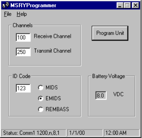
5. Run “MSRY Programmer” on the computer.
6. Input the Receiver Channel, Transmit Channel, and
ID Code.
7. Select “Program Unit”. Select “OK” when
programming is complete.
8. Close “MSRY Programmer” and disconnect the
serial cable from the computer and MSRY Relay.
9. Turn power off to MSRY Relay.
Data Messages
The MSRY Relay has a built in transmitter and receiver. However, it does not incorporate the
same data message features as the MXMT or MMCT transmitters. It receives, stores, and
transmits messages received from MIDS and EMIDS transmitters.
The only data message that can be sent by the MSRY Relay is a test message. When the test
button is pressed, the Relay transmits a message that gives the MSRY ID Code and the data
message “Test”. No other data messages apply to the MSRY Relay.
RF Link
The operational range of the RF link is dependent upon various conditions. The high frequency
of the RF link works best under line of sight conditions. However, operation from gulches and
around buildings or hills is possible for shorter ranges. Dry sand, heavy foliage, and non line-of-
sight can all play a part in decreasing the retransmission range. Retransmission ranges of 25 to
100 miles can be achieved depending on terrain.
QTI Page 6 Revision: F
Form #: 30Z0136 Effective Date: 23 August 2006
Emplacement Considerations
The MSRY must be placed within the transmission range of the transmitter (2-10 miles). For the
best results place the relay half way between the transmitter and the receiver on flat surfaces, or
at the top of a hill or building.
Battery
The MSRY Relay incorporates two each 4-volt, 4.5-amp hour rechargeable sealed lead-acid
batteries. The batteries are fully charged at Qual-Tron prior to shipment to provide a minimum
of 9 volts.
NOTE: Due to the self-discharge characteristics of this type of battery, it is imperative that they
be charged periodically if placed in storage. Otherwise, permanent loss of capacity might occur
as a result of sulfation. It is recommended that the batteries be charged every 2-3 months using
the supplied PSEC AC/DC battery charger to prevent permanent damage to the battery. The
PSEC AC/DC charger (13D0229-1) provides a 12-volt, 1.7-amp input. Use only the 12V PSEC
to charge the batteries, as the 9V PSEC AC/DC adapter (13D0230-1) will not provide adequate
charging. It is recommended that the MSRY batteries be charged for a minimum of 8 hours.
QTI Page 7 Revision: F
Form #: 30Z0136 Effective Date: 23 August 2006

Section 3: Frequency/Channel Calculations
FREQUENCY RANGES
FREQUENCY CHANNEL FREQ.
RANGE MIN MAX
CHANNEL
STEPS MIN MAX
LOW 138.025 154.000 25 kHz 001 640
MID 154.005 162.000 5.0 kHz 001 1600
HIGH 162.00625 174.000 6.25 kHz 001 1920
Channel to Frequency Calculation
Channel * Channel Step + Min Frequency = Frequency for Channel
Examples:
- Low Band Channel 20
- 20 * 0.025 + 138 = 138.5 MHz
- Mid Band Channel 300
- 300 * 0.005 + 154 = 155.5 MHz
Frequency to Channel Calculation
(Frequency - Minimum Frequency) / Channel Step = Channel for Frequency
Examples:
- Low Band 151.5 MHz
- (151.5 - 138) / 0.025 = Channel 540
- High Band 172.5 MHz
- (172.5 - 162) / 0.00625 = Channel 1680
QTI Page 8 Revision: F
Form #: 30Z0136 Effective Date: 23 August 2006
Section 4 FCC Notice / RF Exposure
FCC Notices (U.S. Only)
This equipment has been tested and found to comply with the limits for a Class B digital device
pursuant to Part 15 of the FCC Rules. These limits are designed to provide reasonable protection
against harmful interference when the equipment is operated in a residential installation. This
equipment generates, uses and can radiate radio frequency energy and if not installed and used in
accordance with the manufacturer’s instruction manual, may cause interference with radio
communications. However there is no guarantee that interference will not occur in a particular
installation. If this equipment does cause harmful interference to radio or television reception,
which can be determined by turning the equipment off and on, you are encouraged to try to
correct the interference by one or more of the following measures:
- Reorient or relocate the receiving antenna.
- Increase the separations between the equipment and receiver
- Connect the equipment into an outlet on a circu8it different from that to which the
receiver is connected
- Consult the dealer or experience radio/TV technician for help.
FCC Compliance Information
The following information is provided on the device or devices covered in this document in
compliance with FCC regulations:
• Model Number: QTIMIDSMRLY, QTIEMIDSRSRY
• Company Name:
Qual-Tron, Inc.
9409 E. 55th Pl. S.
Tulsa, OK 74145-8157 USA
918-622-7052
RF Exposure – MPE / SAR
In order to comply with FCC RF Exposure requirements, this device must be installed and
operated in such a way that a minimum separation distance of 20cm is always maintained
between the antenna and all persons during normal operations.
QTI Page 9 Revision: F
Form #: 30Z0136 Effective Date: 23 August 2006