Quanta Computer NL Notebook Computer User Manual NL1 User s Manual 1022
Quanta Computer Inc Notebook Computer NL1 User s Manual 1022
UserManual.wiki
>
Quanta Computer
>
NL User Manual
>
Manual 1
Contents
1.
Manual 1
2.
Manual 2
Manual 1
Navigation menu
Upload a User Manual
Namespaces
Wiki Guide
HTML
PDF
Info
Views
User Manual
Discussion / Help
Navigation
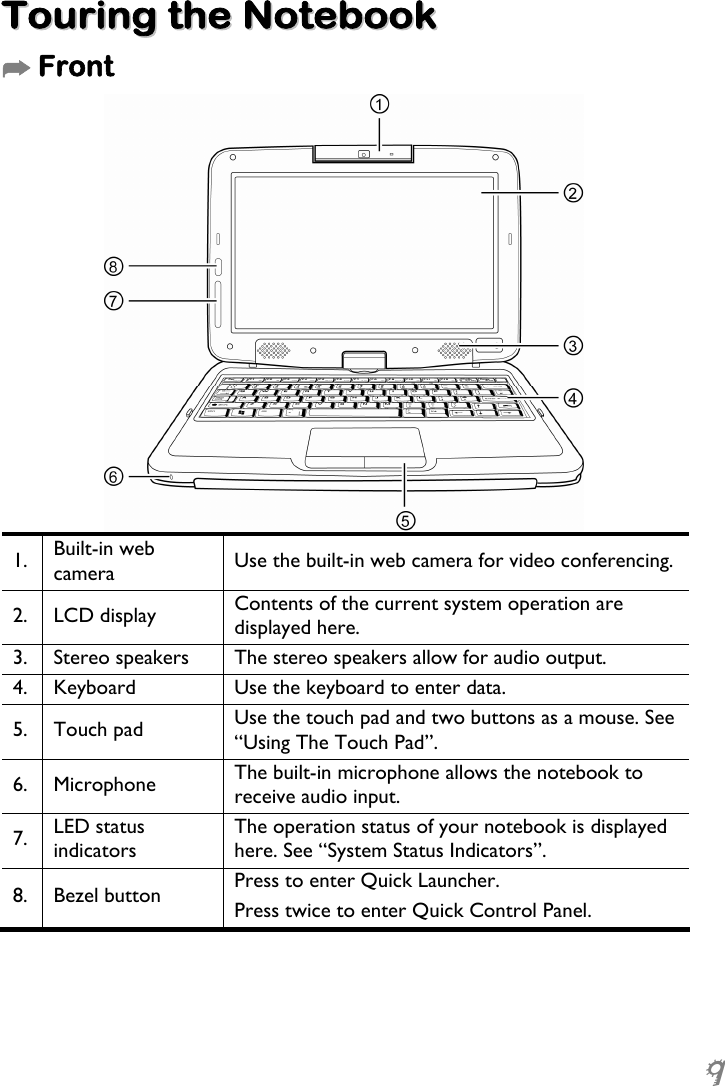
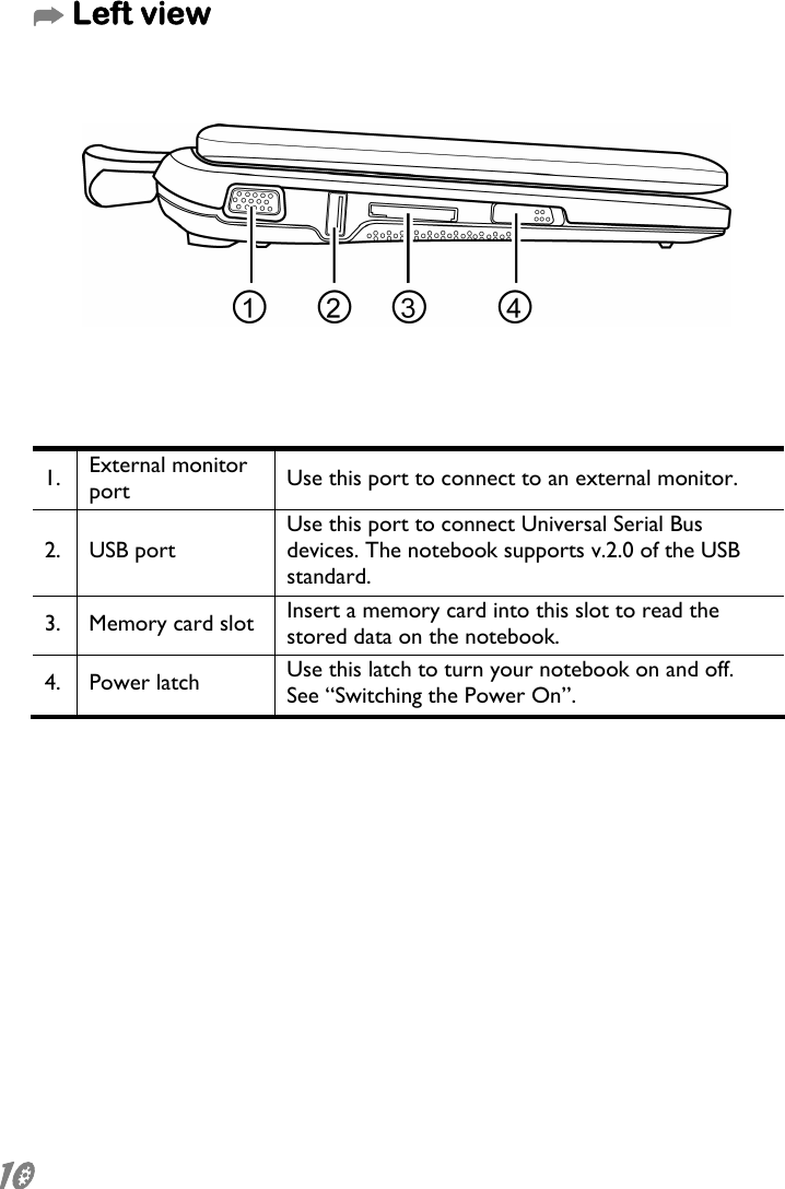
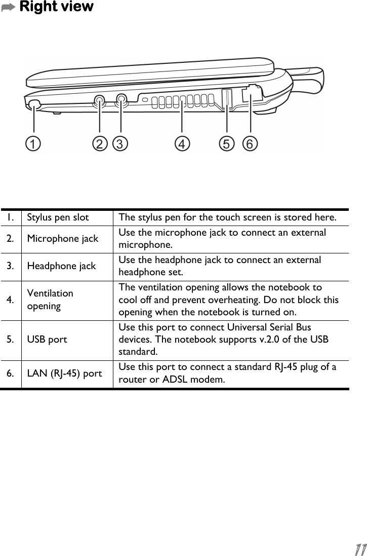
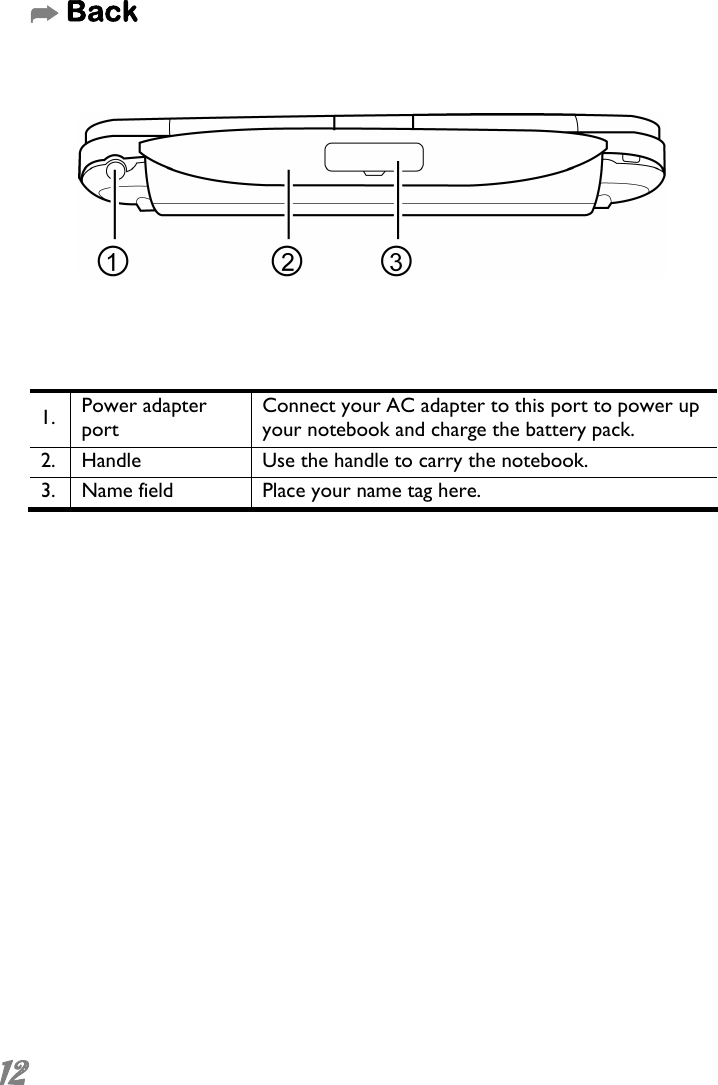
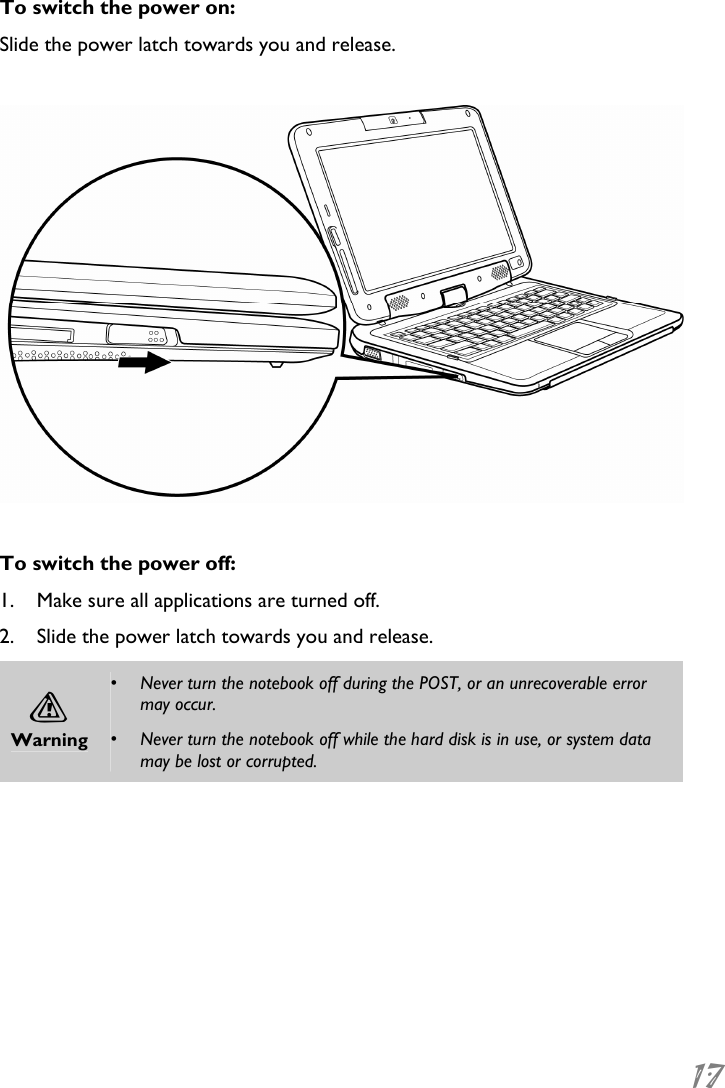
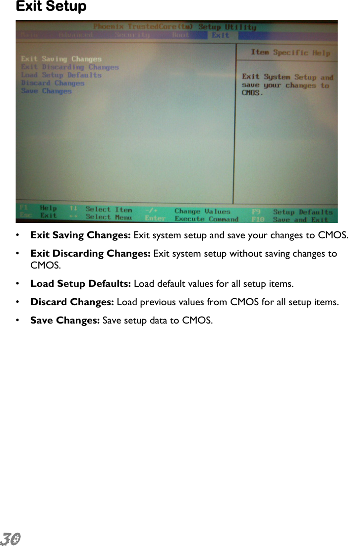
![25 Conserving the Battery Power You can use a combination of key controls to enter the sleep or hibernation mode to conserve the battery power. • In the sleep mode, hardware devices, such as the display panel and hard disk, are turned off to conserve energy. • In the hibernation mode, all system data are saved in the hard disk before powering down. No power or very little power is drawn from the battery module. To enter the sleep mode: Press and hold [Fn + F2]. To enter the hibernation mode in Windows: 1. Press the Windows logo key, and then press [U]. 2. When the popup window appears, press and hold [Shift + H]. To exit the sleep or hibernation mode: Slide the power latch towards you and release. Note When exiting the hibernation mode, the amount of time the system requires to restore all its previous contents can range from five to twenty minutes, depending on how much RAM has been installed on your notebook.](https://usermanual.wiki/Quanta-Computer/NL.Manual-1/User-Guide-1034044-Page-29.png)