Quanta Computer WM100 Mini-PCI Wireless LAN card in Notebook Computer User Manual
Quanta Computer Inc Mini-PCI Wireless LAN card in Notebook Computer
User manual

________________________________________________________________________________________
UANTA COMPUTER INC.
_______________________________________________________________
WM1-Mini-PCI Wireless LAN Card
USER MANUAL
Dec 07, 2001 Revision: 1A
Issued By: frank wang
Checked By:
______________________________________________________________________________
The release of this document is under controlled by the company. Any extra copy of this
document must be written permission by the product manager.
______________________________________________________________________________
- Quanta Confidential -

UANTA COMPUTER INC. WM1 Mini-PCI User Manual
______________________________________________________________________________
_______
________________________________________________________________________
WM1 User Manual Rev. 1A Page: 2
- Quanta Confidential -
Revision Date Remark
1A 12/07/2001 First draft

UANTA COMPUTER INC. WM1 Mini-PCI User Manual
______________________________________________________________________________
_______
________________________________________________________________________
WM1 User Manual Rev. 1A Page: 3
- Quanta Confidential -
Federal Communications Commission Statement
This device complies with FCC Rules Part 15. Operation is subject to the following two conditions:
This device may not cause harmful interference.
This device must accept any interference received, including interference that may cause undesired
operation.
This equipment has been tested and found to comply with the limits for a Class B digital device,
pursuant to Part 15 of the FCC Rules. These limits are designed to provide reasonable protection
against harmful interference in a residential installation. This equipment generates, uses and can
radiate radio frequency energy. If this equipment is not installed and used in accordance with the
manufacturer's instructions, it may cause harmful interference to radio communications. However,
there is no guarantee that interference will not occur in a particular installation. If this equipment
does cause harmful interference to radio or television reception, which can be determined by during
the equipment off and on, the user is encouraged to try to correct the interference by one or more
of the following measures:
Reorient or relocate the receiving antenna.
Increase the separation between the equipment and receiver.
Connect the equipment to an outlet on a circuit different from that to which the receiver is
connected.
Consult the dealer or an experienced radio/TV technician for help.
The use of shielded cables for connection of the monitor to the graphics card is required to assure
compliance with FCC regulations. Changes or modifications to this unit not expressly approved by
the party responsible for compliance could void the user's authority to operate this equipment.
Manufacturer's Disclaimer Statement
The information in this document is subject to change without notice and does not represent a
commitment on the part of the vendor. No warranty or representation, either expressed or implied,
is made with respect to the quality, accuracy or fitness for any particular purpose of this document.
The manufacturer reserves the right to make changes to the content of this document and/or the
products associated with it at any time without obligation to notify any person or organization of
such changes. In no event will the manufacturer be liable for direct, indirect, special, incidental or
consequential damages arising out of the use or inability to use this product or documentation,
even if advised of the possibility of such damages. This document contains materials protected by
copyright. All rights are reserved. No part of this manual may be reproduced or transmitted in any
form, by any means or for any purpose without expressed written consent of its authors. Product
names appearing in this document are mentioned for identification purchases only. All trademarks,
product names or brand names appearing in this document are registered property of their
respective owners.
Printed in Taiwan

UANTA COMPUTER INC. WM1 Mini-PCI User Manual
______________________________________________________________________________
_______
________________________________________________________________________
WM1 User Manual Rev. 1A Page: 4
- Quanta Confidential -
Table of Content
Table Of Content………………………………………………………………….. 4
1 Introduction……………………………………………………………………….. 5
1-1 Overview…………………………………………………………………………… 5
1-2 Features………………………………………………………………………….… 5
2 Wireless LAN Application………………………………………………………... 6
2-1 Ad-Hoc Topology………………………………………………………………….. 6
2-2 Infrastructure Topology…...……………………………………………………… 7
3 Installation Procedure.……………………………………………………………. 8
3-1 For Windows 2000 installation……….…………………………………………... 8
3-2 For Windows 98/ME installation…….…………………………………………… 11
4 Wireless Client Manager Utility…..……………………………………………… 11
5 Technical Specification of Wireless LAN..……………………………………… 19

UANTA COMPUTER INC. WM1 Mini-PCI User Manual
______________________________________________________________________________
_______
________________________________________________________________________
WM1 User Manual Rev. 1A Page: 5
- Quanta Confidential -
1 Introduction
1-1 Overview
The user manual of the model named WM1 will be based on this documentation. The product
complies with full IEEE 802.11b standard with bit rate up to 11Mbps and interface complies
with Mini-PCI specifications. This manual will assist you with the installation procedure and
the operation of Wireless Client Manager utility which is used for managing the wireless LAN
card and establishing the wireless connection with your Local Area Network.
1-2 Features
* Fully IEEE 802.11b and Wi-Fi compatible
* Seamless roaming under 802.11b WLAN infrastructure
* Support 11M/5.5M/2M/1M automatically fall back functionality
* WEP 40/128 bits encryption provided
* User-friendly installation, Auto-detect and easy setup
* Provide Web-based configuration utilities and window-based diagnostics tools
* Good receiving sensitivity and block free design
* Compatible with any computer running Microsoft Windows 98/2000/ME/NT/XP
UANTA COMPUTER INC. WM1 Mini-PCI User Manual
______________________________________________________________________________
_______
________________________________________________________________________
WM1 User Manual Rev. 1A Page: 6
- Quanta Confidential -
2 Wireless LAN Application
Wireless LAN (Local Area Network) systems offer a great number of advantages over a
traditional, wired system. And these systems support the same network configuration options
of the legacy Ethernet LANs as defined by IEEE 802 standard committee. Besides, they are
more flexibles, easier to setup and manage and often more cost effective than wired
equivalence. In general, wireless LAN products can be configured as “Ad-Hoc (Peer-to-
Peer)” for departmental or SOHO LANs or “Infrastructure (Access Point)” for enterprise
LANs.
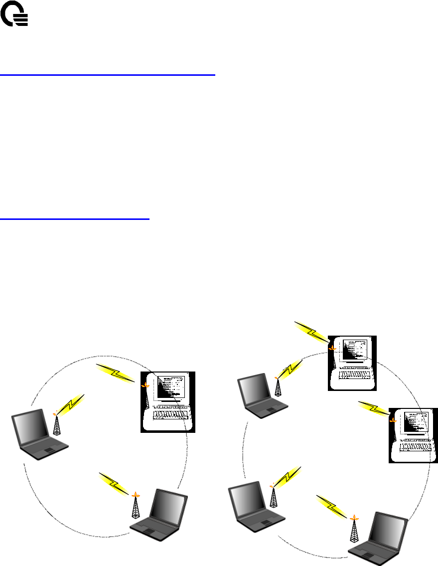
2-1 Ad-Hoc Topology
This is the peer-to-peer mode of operation without access point. An Ad-Hoc wireless LAN is a
group of computers, each equipped with one wireless adapter, connected as an independent
wireless LAN. Computers in a specific Ad-Hoc wireless LAN must be configured at the same
radio channel and the same SSID for establishing the wireless connection. Ad-Hoc wireless
LAN is applicable at a departmental scale for a branch or SOHO operation.
Ad-Hoc Wireless LAN1 Ad-Hoc Wireless LAN2
Notebook with
Wireless NIC
Notebook with
Wireless NIC
Notebook with
Wireless NIC
Notebook with
Wireless NIC
Notebook with
Wireless NIC
Desktop with
Wireless NIC
Desktop with
Wireless NIC
Desktop with
Wireless NIC
UANTA COMPUTER INC. WM1 Mini-PCI User Manual
______________________________________________________________________________
_______
________________________________________________________________________
WM1 User Manual Rev. 1A Page: 7
- Quanta Confidential -
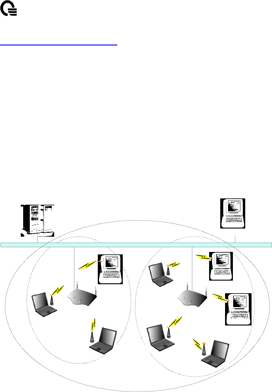
2-2 Infrastructure Topology
This mode of operation requires the presence of an access point at least. In this mode, all
wireless LAN client devices need to communicate with the access point and then access to a
wired LAN such as Ethernet via the access point. Therefore, an integrated wireless and wired
LAN is called an infrastructure configuration. A group of wireless LAN client users and an
access point construct a Basic Service Set (BSS). Each wireless LAN client devices in this
BSS can talk to any devices in the wired LAN infrastructure via the access point. In this
infrastructure configuration, wireless LAN systems will extend the accessibility to the wired
LAN. On the other hand, infrastructure mode also supports roaming capabilities for mobile
wireless LAN users. More than one BSS can be configured as an Extended Service Set (ESS).
The continuous network allow wireless LAN users to roam freely within an ESS. All wireless
LAN client devices and access points within the ESS must be configured with the same ESS
ID and use the same radio channel.
Notebook with
Wireless NIC
Notebook with
Wireless NIC
Notebook with
Wireless NIC
Notebook with
Wireless NIC
Desktop with
Wireless NIC
Desktop with
Wireless NIC
Desktop with
Wireless NIC
Notebook with
Wireless NIC
Access Point Access Point
Ethernet
BSS 1 BSS 2
Desktop with
Ethernet NIC
ESS
UANTA COMPUTER INC. WM1 Mini-PCI User Manual
______________________________________________________________________________
_______
________________________________________________________________________
WM1 User Manual Rev. 1A Page: 8
- Quanta Confidential -
3 Installation Procedure
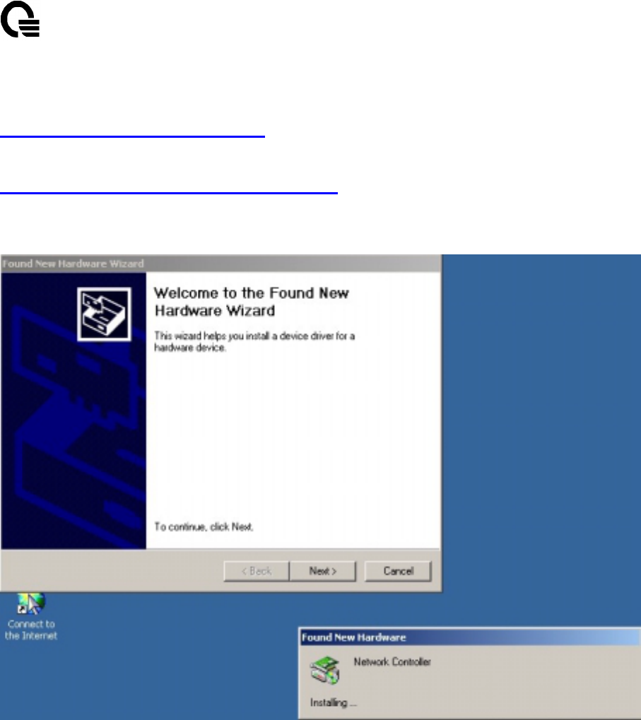
3-1 For Windows 2000 installation
1. Windows 2000 will automatically detect the new hardware and prompt you to install the
driver needed. Click “Next” button to begin the installation.
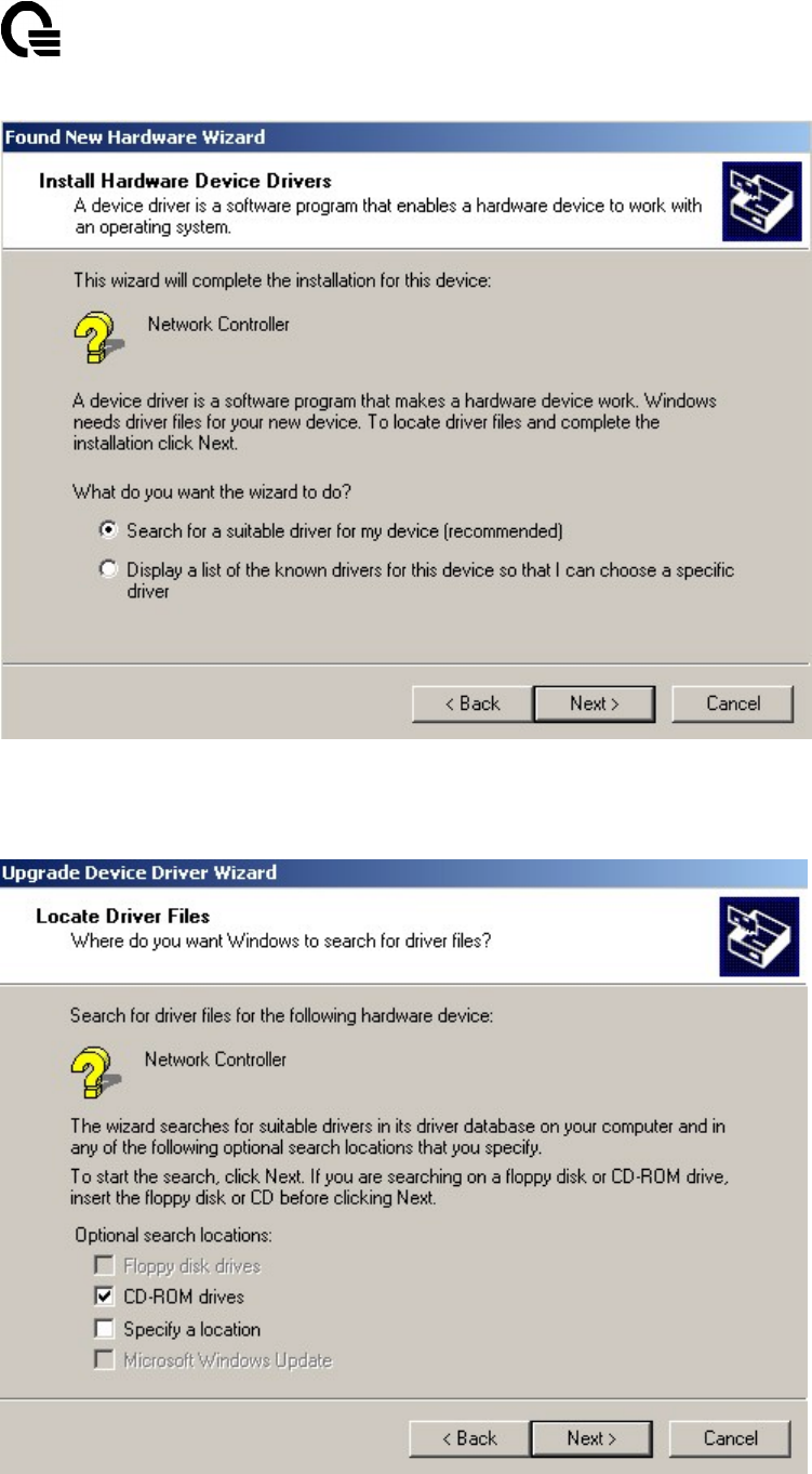
2. Select “Search for a suitable driver for my device [recommended]”, and click “Next”
button.
UANTA COMPUTER INC. WM1 Mini-PCI User Manual
______________________________________________________________________________
_______
________________________________________________________________________
WM1 User Manual Rev. 1A Page: 9
- Quanta Confidential -
1. Select the location where the corresponding driver is placed, “CD-ROM drivers” is the
default location we support, and click “Next” button.

UANTA COMPUTER INC. WM1 Mini-PCI User Manual
______________________________________________________________________________
_______
________________________________________________________________________
WM1 User Manual Rev. 1A Page: 10
- Quanta Confidential -
2. Windows 2000 will show a windows information dialog. Click “Yes” button.
3. Windows 2000 will install the driver. As the driver files are being copied to the
appropriate location, windows 2000 will show a windows information dialog. Users click
“Finish” button to complete the software installation.
UANTA COMPUTER INC. WM1 Mini-PCI User Manual
______________________________________________________________________________
_______
________________________________________________________________________
WM1 User Manual Rev. 1A Page: 11
- Quanta Confidential -
4 Wireless Client Manager Utility
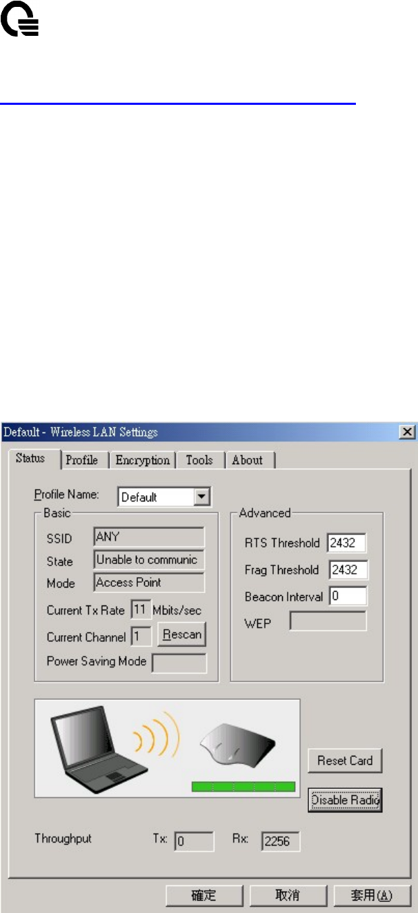
The WM1 Wireless Client Manager (WCM) screen is divided into four tabs :
- Status : provides current information on your wireless connection setting.
- Profile : easily allows users to configure those different setting for each profile.
- Encryption : prevent unauthorized users from accessing your wireless network.
- About : provides valuable information on the version and build numbers of WCM.
Status Tab
The Status tab provides information on the current profile, if any, being used in your wireless
connection. The information listed on the Status tab is indicated below.
Profile Name
Basic – SSID, State, Mode, Current Tx Rate, Current Channel, Power Saving Mode
Advanced – RTS Threshold, Frag Threshold, Beacon Interval, WEP

UANTA COMPUTER INC. WM1 Mini-PCI User Manual
______________________________________________________________________________
_______
________________________________________________________________________
WM1 User Manual Rev. 1A Page: 12
- Quanta Confidential -
Profile Name
The name of the profile currently in use.
Basic
SSID
The name of the SSID (Service Set Identification) associated with the profile
State
This field is used to display the current state of the driver. When the state “associated” means
normal flow of operation in access point or peer-to-peer devices. During access point
connection, it will represent the MAC address of the access point. And during an Ad-Hoc
connection, it will read the MAC address of the peer-to-peer devices. A state of “scanning”
means that the node is searching for available access point and can not detect any wireless
device within range.
Mode
It will be shown the access point or peer-to-peer in this field.
Access point – This mode of operation requires the presence of an access point. All
communication is done via the access point, which relays packets to other wireless clients in
the BSS as well as to nodes on a wired network such as Ethernet.
Peer-to-peer – This is the peer-to-peer mode of operation. All communication is done from
client to client without the use of an access point.
Current Tx Rate
It will shown the transmit rate is being currently used for an active connection. This value has
no meaning when state is “scanning”
Current Channel
Channel being used, if any, for this wireless connection. It will shown the communication
channel ranging from 1 to 11.
Power Saving Mode
Indicates of power saving mode is enable or disable. Power saving mode reduced energy
usage by temporarily disconnecting wireless connections when the connection is idle.
Rescan
Pressing the rescan button causes the driver to restart and begin its connection procedure. The
connection procedure differs depending on the mode of the driver.
Advance
RTS Threshold
Indicated of RTS threshold is disable or the value ranging from 0 to 2432.
Frag Threshold
Indicated of frag threshold is disable or the value ranging from 256 to 2432.
Beacon Interval
Indicated of beacon interval is disable or the ranging from 20 to 1000.
UANTA COMPUTER INC. WM1 Mini-PCI User Manual
______________________________________________________________________________
_______
________________________________________________________________________
WM1 User Manual Rev. 1A Page: 13
- Quanta Confidential -
WEP
Indicated of WEP is disable, 64 bit or 128 bit.
Throughput
These two fields display the instantaneous wireless receive and transmit throughput displayed
in bytes per second. These values are updated every two seconds.
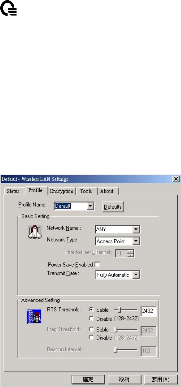
Profile Tab
The Profile tab is used to configure the various profiles available to you for wireless
connections. The Profile tab contains some of the same fields as the Status tab, but unlike the
Status tab, all of the fields in the Profile tab are alterable.
Profile Name, Defaults
Basic – SSID, State, Mode, Current Tx Rate, Current Channel, Power Saving Mode
Advanced – RTS Threshold, Frag Threshold, Beacon Interval, WEP
Profile Name

UANTA COMPUTER INC. WM1 Mini-PCI User Manual
______________________________________________________________________________
_______
________________________________________________________________________
WM1 User Manual Rev. 1A Page: 14
- Quanta Confidential -
Name given to the profile. Any user can add 10 maximum different profiles if he wish.
Defaults
Pressing this button restores each field in the panel to its default value. The default value for
each field as below.
Basic
SSID
The name of the SSID (Service Set Identification) associated with the profile. The default
value is “ANY”, This allows your wireless client to automatically associate to any access
point in the vicinity of your wireless client.
Mode
This field allows you to select from a list of supported network mode. The modes displayed
will have “Access Point” and “Peer-to-Peer. The default value is “Access Point”.
Current Tx Rate
The transmission rate at which the data packets are transmitted by client of access point. You
can set this to 1Mbps, 2Mbps, Auto 1 or 2Mbps, 5.5Mbps, 11Mbps, Fully Automatic. The
default value is “Fully Automatic”.
Peer-to-Peer Channel
Changing the channel is only effective in Ad-Hoc networks. Networking operating
infrastructure mode automatically scan for a channel. Be aware that when the peer-to-peer
mode is selected, be sure to set your wireless stations with the same channel.
Power Saving Mode
The field allows you to set enable or disable. Power saving mode reduced energy usage by
temporarily disconnecting wireless connections when the connection is idle. The default value
is “Disable”.
Advance
RTS Threshold
The field allows you to set enable or disable. When the field is enable, you can set the value
ranging from 0 to 2432. RTS threshold is a mechanism implemented to prevent the “Hidden
Node” problem. “Hidden Node” is a situation in which two stations are within range of the
same access point, but are not within range of each other. Thus, it provides a solution to
prevent data collisions. Enabling RTS Threshold may cause redundant network overhead that
could negatively affect the throughput performance.
Frag Threshold
The field allows you to set enable or disable. When the field is enable, you can set the value
ranging from 256 to 2432. Fragmentation mechanism is used for improving the efficiency
when high traffic flows along in the wireless network. If your wireless devices often transmit
large files in wireless network, you can enable the Fragmentation Threshold and the
mechanism will split the packet.
Beacon Interval

UANTA COMPUTER INC. WM1 Mini-PCI User Manual
______________________________________________________________________________
_______
________________________________________________________________________
WM1 User Manual Rev. 1A Page: 15
- Quanta Confidential -
Changing the Beacon Interval is only effective in peer-to-peer mode. You can set the value
ranging from 20 to 1000.
Encryption Tab
The Encryption tab is used to desire an additional measure of security on your wireless
network, which can be achieved by using WEP (Wired Equivalent Privacy) encryption. To
prevent unauthorized wireless stations from accessing data transmitted over the network,
WEP can support high secure data encryption. WEP encrypts each frame transmitted from
the radio using one of the Keys entered from this panel. When an encrypted frame is received,
it will only be accepted if it decrypts correctly. This will only happen if the receiver has the
WEP Key used by the transmitter. The Encryption tab contains some fields as below.
Encryption [WEP security]
WEP Key – Create Key Manually, Create Keys with Pass-phrase
Key1, Key2, Key3, Key4
Use WEP key
Encryption [WEP security]
The field allows you to set Disabled, 64-bit, 128-bit. When setting 64bit, or 128 bits, it means

UANTA COMPUTER INC. WM1 Mini-PCI User Manual
______________________________________________________________________________
_______
________________________________________________________________________
WM1 User Manual Rev. 1A Page: 16
- Quanta Confidential -
WEP security is used.
WEP Key
You can use “Create Key Manually” or “Create Keys with Pass-phrase” method to enter
encryption keys. It allows the entry of four keys for 64-bit encryption and one set of 128-bit
key according to WEP function select. To be written to the driver and registry, each key must
consists of correct digits and letters. The detailed descriptions will be shown as below for
these two kinds of methods:
Create Key Manually
For 40-bits encryption:
- Five alphanumeric characters in the range of “a-z”, “A-Z” and “0-9”. (e.g. MyKey)
- 10 digit hexadecimal values in the range of “A-F” and “0-9”. (e.g. 11AA22BB33).
For 128-bits encryption:
- 13 alphanumeric characters in the range of “a-z”, “A-Z” and “0-9”. (e.g. WEPencryption).
- 26 digit hexadecimal values in the range of “A-F” and “0-9”. (e.g.
11AA22BB33123456789ABCDEFF)
.
Create Keys with Pass-phrase
A Pass-phrase can be entered which is used as a “seed” to randomly generate the four keys.
This saves considerable time since the same keys must be entered into each node on the
wireless network.
Key1, Key2, Key3, Key4
These four fields can be used to manually enter the keys. This may be necessary if you wish
this node to match keys in a different vendor product. These fields also display the keys when
they are generated using a Pass-phrase.
Use WEP key
This field updates the driver with the four keys displayed in Key1 through Key4. These keys
are also written to the registry for permanent storage. For 128 bit encryption, this field will be
invisible.
About Tab
The about tab is used to show Frequency Domain, Wireless Client management Utility
version, Serial Number and MAC Address of this Network Interface Card, Network Interface
Card Driver version and Network Interface Card firmware version. Users need to use these
version numbers when reporting their problems to technique support.

UANTA COMPUTER INC. WM1 Mini-PCI User Manual
______________________________________________________________________________
_______
________________________________________________________________________
WM1 User Manual Rev. 1A Page: 17
- Quanta Confidential -

UANTA COMPUTER INC. WM1 Mini-PCI User Manual
______________________________________________________________________________
_______
________________________________________________________________________
WM1 User Manual Rev. 1A Page: 18
- Quanta Confidential -
5. Technical Specification of Wireless LAN
Standard Compliance
IEEE 802.11b standard and WECA interoperability certified FCC part 15•sec.15. 247/USA
CE/ETSI 300.328•300.826/Eurpoe
TELEC/Japan
Electrical Specification
Supply voltage range: 3.0V~3.6V DC ripple 1% less
Average current t: 218 mA typical 2% transmit• 98% receive
without power saving mode
Average current: 40 mA typical 2% transmit• 8% receive
90% standby with power saving mode
Continuous transmit mode: 380 mA max
Continuous receive mode: 215 mA max
Standby mode: 17 mA max with power saving mode
Form Factor
Comply with Mini-PCI type •B Form Factor.
Connectivity Specification
Mini-PCI Interface•release 1.0•
Environmental Specification
Temperature Range: 0~55ºC• Operation -
20~65ºC• Storage
Relative Humidity: 95% max
Vibration: 15G 10 to 2000Hz• non-operating
EMI: FCC class B
ESD: 1500V Non-operating
Frequency Allocation
North America: 2412~2462MHZ 11channels•3 non-overlapping•
Europe: 2412~2472MHZ 13channels•3 non-overlapping•
Japan: 2412~2484MHZ 14channels
Modulation/Data rate

UANTA COMPUTER INC. WM1 Mini-PCI User Manual
______________________________________________________________________________
_______
________________________________________________________________________
WM1 User Manual Rev. 1A Page: 19
- Quanta Confidential -
Direct sequence spread spectrum•DSSS•
1M bps DBPSK 5.5M bps CCK
2M bps DQPSK 11M bps CCK
Antenna Specification
Two Antenna ports provided for Space Diversity
Port Impedance 50 ohms
Receive Sensitivity
1M bps -87dBm Max 8% PER or less
2M bps -85dBm Max 8% PER or less
5.5M bps -84dBm Max 8% PER or less
11M bps -82dBm Max 8% PER or less
Dynamic Range
85dB typical Max. input level -5dBm
System Linearity•Input•
Input third order intercept point
IIP3_90 -15 dBm Min. -90dBm input
IIP_25 10 dBm Min. -25dBm input
Image Rejection
Image rejection: 60dB Min. PER<8%
System Linearity•Output•
Adjacent channel rejection 40 Min. PER<8% @25MHz jammer offset
Transmitter Power Output
TXP: 14±1dBm measured at antenna port
1st side lobe < -30dBc
2nd side lobe < -50dBc
TXP Range•ALC on•0dB typical
Carrier Suppression

UANTA COMPUTER INC. WM1 Mini-PCI User Manual
______________________________________________________________________________
_______
________________________________________________________________________
WM1 User Manual Rev. 1A Page: 20
- Quanta Confidential -
15dB Min.
Preamble Length
Short/Long
Multipath Fading Equalization
RAKE receiver incooperated•targeted for multipath delay spread•
125 ns rms at 11Mbps•200 ns rms at 5.5 Mbps and 500 ns rms at 1 or 2M bps