Quanta Microsystems US305 IEEE 802.11bgn WLAN USB 2.0 module User Manual
Quanta Microsystems, Inc. IEEE 802.11bgn WLAN USB 2.0 module
User Manual

Quanta Microsystems, Inc.
Tel
:
+886-3-3979000 Fax
:
+886-3-397990
5F, No.188, WenHwa 2nd RdKuei Shan Hsiang,
Taoyuan Shien, 333,Taiwan
Product Specification
&
User’s Manual
Model Name:US305
IEEE 802.11n WLAN
USB 2.0 Module
Version: 0.0
Date: 2011/2/11

2
U.S. Regulatory Wireless Notice
Federal Communication Commission Interference Statement
This equipment has been tested and found to comply with the limits for a Class B
digital device, pursuant to Part 15 of the FCC Rules. These limits are designed to
provide reasonable protection against harmful interference in a residential
installation. This equipment generates, uses and can radiate radio frequency
energy and, if not installed and used in accordance with the instructions, may cause
harmful interference to radio communications. However, there is no guarantee that
interference will not occur in a particular installation. If this equipment does cause
harmful interference to radio or television reception, which can be determined by
turning the equipment off and on, the user is encouraged to try to correct the
interference by one of the following measures:
- Reorient or relocate the receiving antenna.
- Increase the separation between the equipment and receiver.
- Connect the equipment into an outlet on a circuit different from that
to which the receiver is connected.
- Consult the dealer or an experienced radio/TV technician for help.
FCC Caution: Any changes or modifications not expressly approved by the party
responsible for compliance could void the user's authority to operate this
equipment.This device complies with Part 15 of the FCC Rules. Operation is subject
to the following two conditions: (1) This device may not cause harmful interference,
and (2) this device must accept any interference received, including interference
that may cause undesired operation.
IMPORTANT NOTE:
FCC Radiation Exposure Statement:
This equipment complies with FCC radiation exposure limits set forth for an
uncontrolled environment. This equipment should be installed and operated with
minimum distance 20cm between the radiator & your body.
This transmitter must not be co-located or operating in conjunction with any other
antenna or transmitter.
This device is intended only for OEM integrators under the following
conditions :
1) The antenna must be installed such that 20 cm is maintained between the
antenna and users, and
2) The transmitter module may not be co-located with any other transmitter or
antenna,
As long as 2 conditions above are met, further transmitter test will not be required.

3
However, the OEM integrator is still responsible for testing their end-product for any
additional compliance requirements required with this module installed
IMPORTANT NOTE: In the event that these conditions can not be met (for example
certain laptop configurations or co-location with another transmitter), then the FCC
authorization is no longer considered valid and the FCC ID can not be used on the
final product. In these circumstances, the OEM integrator will be responsible for
re-evaluating the end product (including the transmitter) and obtaining a separate
FCC authorization.
End Product Labeling
This transmitter module is authorized only for use in device where the antenna may
be installed such that 20 cm may be maintained between the antenna and users.
The final end product must be labeled in a visible area with the following: “Contains
FCC ID: T5U-US305”.
Manual Information To the End User
The OEM integrator has to be aware not to provide information to the end user
regarding how to install or remove this RF module in the user’s manual of the end
product which integrates this module.
The end user manual shall include all required regulatory information/warning as
show in this manual.

4
Canadian Regulatory Wireless Notice
This device complies with RSS-210 of the Industry Canada Rules. Operation is
subject to the following two conditions:
1) this device may not cause interference and
2) this device must accept any interference, including interference that may cause
undesired operation of the device
This device is intended only for OEM integrators under the following
conditions:
1) The antenna must be installed such that 20 cm is maintained between the
antenna and users, and
2) The transmitter module may not be co-located with any other transmitter or
antenna,
As long as 2 conditions above are met, further transmitter test will not be required.
However, the OEM integrator is still responsible for testing their end-product for any
additional compliance requirements required with this module installed
IMPORTANT NOTE: In the event that these conditions can not be met (for example
certain laptop configurations or co-location with another transmitter), then the
CANADA authorization is no longer considered valid and the CANADA ID can not
be used on the final product. In these circumstances, the OEM integrator will be
responsible for re-evaluating the end product (including the transmitter) and
obtaining a separate CANADA authorization.
End Product Labeling
This transmitter module is authorized only for use in device where the antenna may
be installed such that 20 cm may be maintained between the antenna and users.
The final end product must be labeled in a visible area with the following: “Contains
IC: 7424A-US305”.
Manual Information To the End User
The OEM integrator has to be aware not to provide information to the end user
regarding how to install or remove this RF module in the user’s manual of the end
product which integrates this module.
The end user manual shall include all required regulatory information/warning as
show in this manual.
IMPORTANT NOTE:
IC Radiation Exposure Statement:
This equipment complies with IC radiation exposure limits set forth for an
uncontrolled environment. This equipment should be installed and operated with
minimum distance 20cm between the radiator and your body.

5
Ce dispositif est conforme à la norme CNR-210 d'Industrie Canada applicable
aux appareils radio exempts de licence. Son fonctionnement est sujet aux
deux conditions suivantes: (1) le dispositif ne doit pas produire de brouillage
préjudiciable, et (2) ce dispositif doit accepter tout brouillage reçu, y compris
un brouillage susceptible de provoquer un fonctionnement indésirable.
Cet appareil est conçu uniquement pour les intégrateurs OEM dans les
conditions suivantes: (Pour utilisation de dispositif module)
1) L'antenne doit être installée de telle sorte qu'une distance de 20 cm est
respectée entre l'antenne et les utilisateurs, et
2) Le module émetteur peut ne pas être coïmplanté avec un autre émetteur ou
antenne,
Tant que les 2 conditions ci-dessus sont remplies, des essais supplémentaires
sur l'émetteur ne seront pas nécessaires. Toutefois, l'intégrateur OEM est
toujours responsable des essais sur son produit final pour toutes exigences de
conformité supplémentaires requis pour ce module installé.
NOTE IMPORTANTE:
Dans le cas où ces conditions ne peuvent être satisfaites (par exemple pour
certaines configurations d'ordinateur portable ou de certaines co-localisation
avec un autre émetteur), l'autorisation du Canada n'est plus considéré comme
valide et l'ID IC ne peut pas être utilisé sur le produit final. Dans ces
circonstances, l'intégrateur OEM sera chargé de réévaluer le produit final (y
compris l'émetteur) et l'obtention d'une autorisation distincte au Canada.
Plaque signalétique du produit final
Ce module émetteur est autorisé uniquement pour une utilisation dans un
dispositif où l'antenne peut être installée de telle sorte qu'une distance de
20cm peut être maintenue entre l'antenne et les utilisateurs. Le produit final
doit être étiqueté dans un endroit visible avec l'inscription suivante: "Contient
des IC: 7424A-US305".
Manuel d'information à l'utilisateur final
L'intégrateur OEM doit être conscient de ne pas fournir des informations à
l'utilisateur final quant à la façon d'installer ou de supprimer ce module RF
dans le manuel de l'utilisateur du produit final qui intègre ce module.
Le manuel de l'utilisateur final doit inclure toutes les informations
réglementaires requises et avertissements comme indiqué dans ce manuel.

6
NOTE IMPORTANTE: (Pour l'utilisation de dispositifs mobiles)
Déclaration d'exposition aux radiations:
Cet équipement est conforme aux limites d'exposition aux rayonnements IC
établies pour un environnement non contrôlé. Cet équipement doit être installé
et utilisé avec un minimum de 20 cm de distance entre la source de
rayonnement et votre corps.

7
Contents
1. Revision History...................................................................................................8
2. Related Documents ..............................................................................................8
3. Overview...............................................................................................................9
3.1. Scope..........................................................................................................9
3.2. Features......................................................................................................9
3.3. Specification ............................................................................................10
3.4. Mechanical Characteristics ......................................................................11
3.5. RoHS Compliant......................................................................................12
4. Engineering sheets .............................................................................................12

8
1. Revision History
Date Release Author Description
2011/2/11 0.0 Jack Ong First release
2. Related Documents
Date Author Document(s)
February 2011 Atheros AR9271L datasheet

9
3. Overview
3.1. Scope
This document describes the specifications of US305 WLAN USB
module. The low power consumption and smaller size are suitable for USB
adapter.
US305 implements half-duplex OFDM, CCK, and DSSS baseband
processing supporting relevant IEEE 802.11n data rates. The MAC
supports the IEEE 802.11 wireless MAC protocol as well as 802.11i
security, receive and transmit filtering, error recovery, quality of service
(QoS), and Extended Range technology, dramatically increasing WLAN
performance.
3.2. Features
BPSK, QPSK, 16 QAM, 64 QAM, DBPSK, DQPSK and CCK
modulation techniques
Operates at 2.4GHz frequency band
802.11e compatible bursting
Supports Windows XP, Windows Vista, Windows 7, Linux kernel
2.6.20 or above.
USB bus powered, external power is no required.
Support Pre-IEEE 802.11n (draft 3.0), short GI and long GI, 20MHz
and 40 MHz bandwidth with data rate up to 150Mbps maximum.
Supports Ad-hoc mode in IEEE 802.11b, Ad-hoc G (802.11g OFDM
rates) and Ad-hoc N (802.11n rates) modes.
802.11n SSN technique (1Transmit/1Receive).
Supports Infrastructure mode in 802.11b and 802.11g modes.
Supports Site survey: 802.11n/g/b BSS and IBSS.
Supports USB adapter hot-swap, device driver disable/enable.
Supports Radio On/Off in software.
Supports IEEE 802.1x,
i Authentication modes: Open system, Share Key, Auto Switch,
IEEE 802.1x, WPA, WPA-PSK, WPA2, WPA2-PSK
ii Encryption method: WEP 64/128, TKIP, AES
USB 2.0(High/Full Speed) and backward compatible with USB 1.1
(Full Speed).
10
3.3. Specification
Standards
Conformity IEEE 802.11n Frequency
Range 11b/g/n: 2.412~2.4835GHz
Type USB 2.0 with 4 pins WTB connector Channels
11b/g: CH1~11(FCC), 1~13(CE)
11n (HT20): CH1~11 (FCC),1~13(CE)
11n (HT40): CH3~9(FCC),3~11(CE)
Modulation
Technique OFDM/ BPSK/ QPSK/ CCK Data Rate
(Mbps)
1Mbps to 11Mbps for 11b,
6Mbps to 54Mbps for 11g,
MCS0 to MCS7 for 11n HT20/HT40
Device Drivers
Windows XP SP2 32bit/64bit
Linux kernel 2.6.20 or above.
Windows Vista 32/64bit
Windows 7
Security
Supports 64-bit & 128-bit WEP for
legacy mode
WPA/WPA2/WPS for all modes
Operating
Voltage DC 3.3V via USB bus power Coverage
Area
60Meters (Indoor)
80Meters (Outdoor)
Warranty 1 year limited warranty Temperature 0 ~ 60°C (Operation)
-20~70°C (Storage)
Sensitivity
Data rate Typical
11Mbps CCK (11b) - 87 dBm
54Mbps OFDM(11g) - 73 dBm
11n HT20 MCS7 - 70 dBm
11n HT40 MCS7 - 66 dBm
Output
Power
Data rate Typical
11Mbps CCK (11b) +19 dBm
54Mbps OFDM(11g) +15 dBm
6Mbps OFDM (11g) +15 dBm
HT20 MCS7 +13.5 dBm
HT40 MCS7 +10.5 dBm
Current
Consumption
Mode Watts/mA@3.3v
11b T
X
1.188
/
360
11
g
T
X
0.990
/
300
11n HT20 T
X
1.254
/
380
11n HT40 T
X
1.188
/
360
11b R
X
0.627
/
190
11
g
R
X
0.627
/
190
11n HT20 RX 0.66
/
200
11n HT40 RX 0.825
/
250
Radio Off 0.660
/
220
11
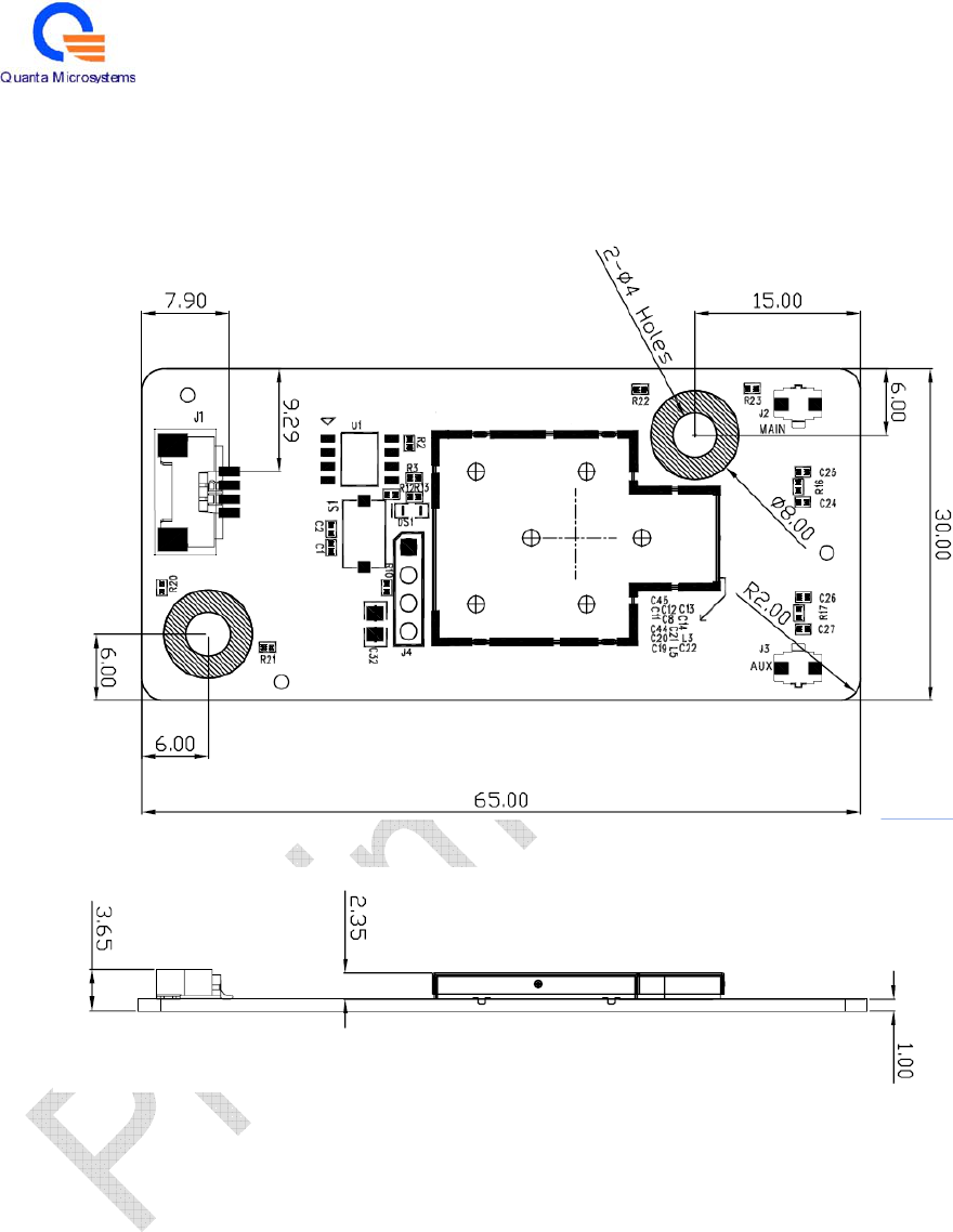
3.4. Mechanical Characteristics
Dimension : 30 x 65 x 3.65mm

12
3.5. RoHS Compliant
US30AR is fully compliant with RoHS requirements.
4. Engineering sheets
Pins Out and Pin Descriptions
Pin no. Definition Pin no. Definition
1 3.3V 2 USB data differential input (D-)
3 USB data differential input (D+) 4 GND
Table of Contents
INTRODUCTION ...................................................................................................1
WIRELESS NETWORK OPTIONS ...............................................................................1
The Peer-to-Peer Network .........................................................................1
The Access Point Network ........................................................................2
SOFTWARE INSTALLATION.............................................................................3
INSTALL THE DEVICE ..............................................................................................3
INSTALL THE DRIVER &UTILITY ............................................................................3
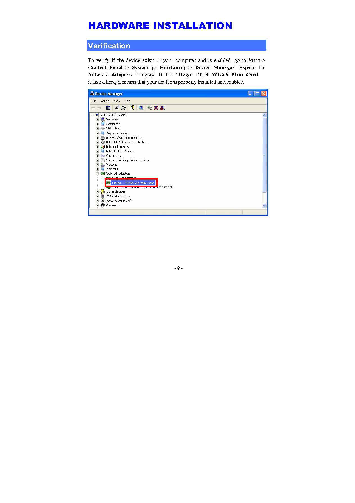
HARDWARE INSTALLATION............................................................................8
VERIFICATION ........................................................................................................8
NETWORK CONNECTION .................................................................................9
INWINDOWS 2000/ XP ..........................................................................................9
IP ADDRESS .........................................................................................................11
CONFIGURATION UTILITY.............................................................................12
INTELLIGENT WIRELESS UTILITY ..........................................................................13
Profile ......................................................................................................13
Network ...................................................................................................22
Advanced.................................................................................................27
Statistics...................................................................................................29
WMM / QoS............................................................................................32
WPS.........................................................................................................33
Radio On/Off ...........................................................................................36
About .......................................................................................................36
UNINSTALLATION.............................................................................................38
-1 -
INTRODUCTION
The 11b/g/n 1T2R WLAN Mini Card is a device that allows you
connect your computer to a wireless local area network (LAN). A wireless LAN
allows your system to use wireless Radio Frequency (RF) technology to transmit
and receive data without physically attaching to the network. The Wireless
protocols that come with this product ensure data security and isolation from
interference generated by other radio frequencies.
This card also allows you to take full advantage of your computer’s mobility with
access to real-time information and online services anytime and anywhere. In
addition, this device eliminates the bother of pulling cable through walls and
under furniture. It even allows you to place your system in locations where
cabling is impossible. Modifying and augmenting networks has never been so
easy.
Wireless Network Options
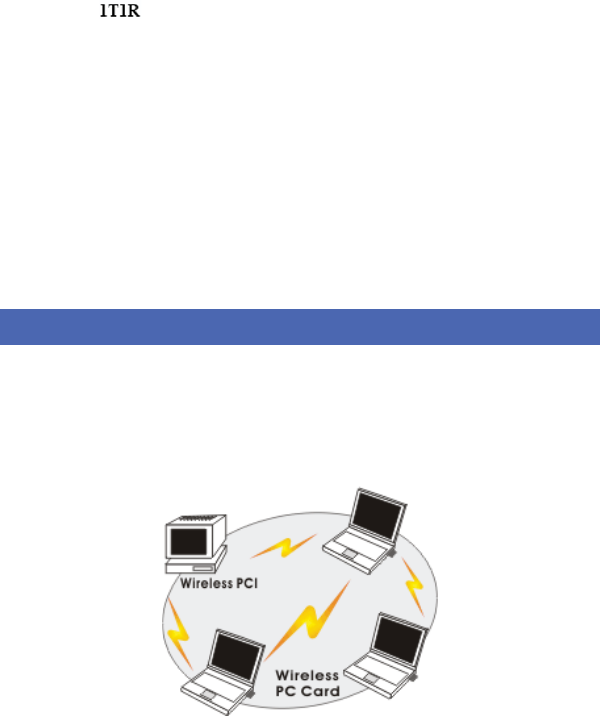
The Peer-to-Peer Network
This network installation lets you set a small wireless workgroup easily and
quickly. Equipped with wireless PC Cards or wireless PCI, you can share files
and printers between each PC and laptop.
1T
1
1T
1
1T
1
1
1T
T
1T
1T
T
T
T
T
T
T
T
T
T
T
T
1T
1T
1
1
1
1
T
1
1
1
1
1
2R
R
2R
2R
R
2R
2R
2R
2R
R
R
R
R
R
R
R
R
R
R
R
R
R
R
R
R
R
R
R
2R
R
R
R
R
R
R
R
R
R
R
R
R
R
R
R
R
R
R
R
-2 -
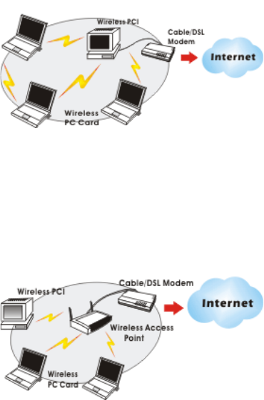
You can also use one computer as an Internet Server to connect to a wired global
network and share files and information with other computers via a wireless LAN.
The Access Point Network
The network installation allows you to share files, printers, and Internet access
much more conveniently. With Wireless LAN Cards, you can connect wireless
LAN to a wired global network via an Access Point.

-3 -
SOFTWARE INSTALLATION
Install the device
1. Make sure the computer is turned off. Remove the expansion slot
cover from the computer.
2. Carefully slide the 11b/g/n 1T2R WLAN Mini Card
into the mini PCI slot. Push evenly and slowly and ensure it is
properly seated.
3. After the device has been connected to your computer, turn on your
computer. Windows will detect the new hardware and then
automatically copy all of the files needed for networking.
Install the Driver & Utility
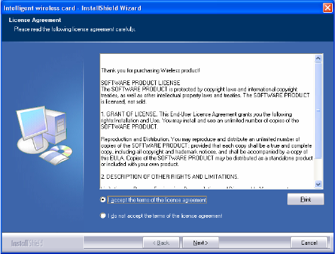
1. Exit all Windows programs. Insert the included CD-ROM into your
computer. The CD-ROM will run automatically.
2. When the License Agreement screen appears, please read the
contents and select “I accept the terms of the license agreement
“ then click Next to continue.
1T
1
1
1T
1T
1T
1T
1T
1T
1T
T
T
1
1T
1
T
T
T
T
T
T
T
T
T
T
T
1
1
T
1
1
T
T
T
T
T
1
1
T
T
T
2R
2R
2
2R
R
R
2R
2R
2R2R
2R
R
R
2R
2R
2
2R
2R
2R
2
R
R
R
R
R
2R
2R
R
2
2
R
R
R
R
2R
R
R
R
R
R
R
R
R
R
R
R
R
R
R
R
-4 -
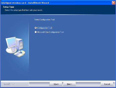
3. Select the check box to choose a Configuration Tool from the listed
two choices.
zConfiguration Tool: Choose to use our configuration utility.
zMicrosoft Zero Configuration Tool: Choose to use Windows XP’s
built-in Zero Configuration Utility (ZCU).
Click Next to continue.
-5 -
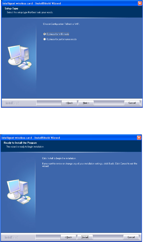
4. There are two modes for you to choose in this screen, either choose
WiFi mode or performance mode (TxBurst mode). This mode
selection screen is set for the default mode shown in the utility screen,
you can still change its mode later in the utility screen. Click Next to
continue.
-6 -
5. When you are prompted the following message, please click Install
to begin the installation.
-7 -
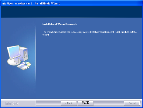
6. When the following screen appears, click Finish to complete the
software installation.
-9 -
NETWORK CONNECTION
Once the device driver is well installed, a network setting described in the
following should be also established.
In Windows 2000/ XP
1. (In Windows 2000)
Go to Start
Æ
Settings
Æ
Control Panel
Æ
Network and Dial-up
Connections
Æ
Local Area Connection
Æ
Properties.
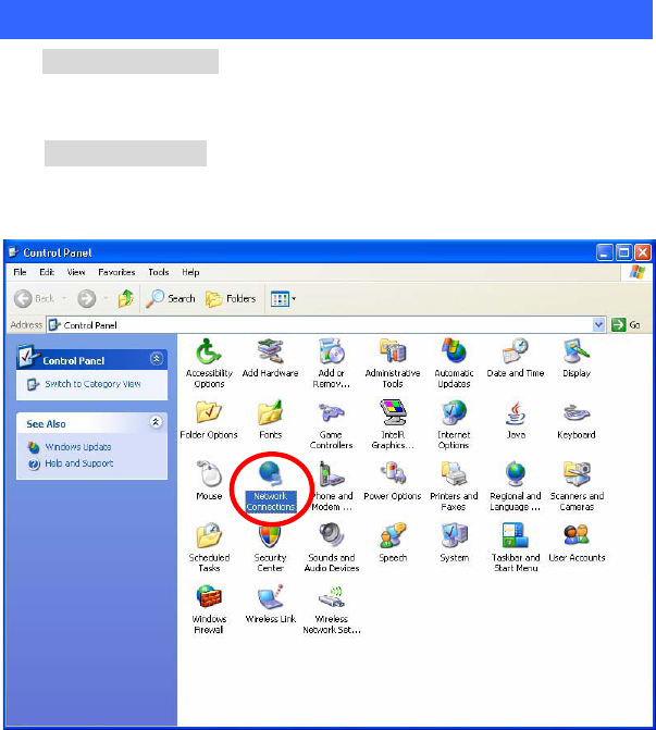
(In Windows XP)
Go to Start
Æ
Control Panel
Æ
Network and Internet Connections
Æ
Network Connections
Æ
Wireless Network Connection
Æ
Properties.
-10 -
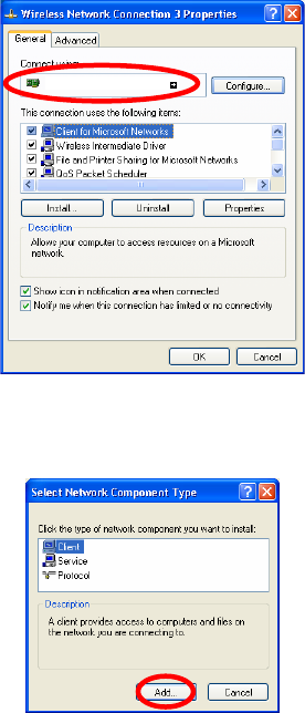
2. Make sure that all the required components are installed.
3. If any components are missing, click on the Install… button to
select the Client/Service/Protocol required. After selecting the
component you need, click Add… to add it in.
4. For making your computer visible on the network, make sure you
have installed File and Printer Sharing for Microsoft Networks.
11b/
g
/n 1T1R WLAN Mini Car
d
-11 -
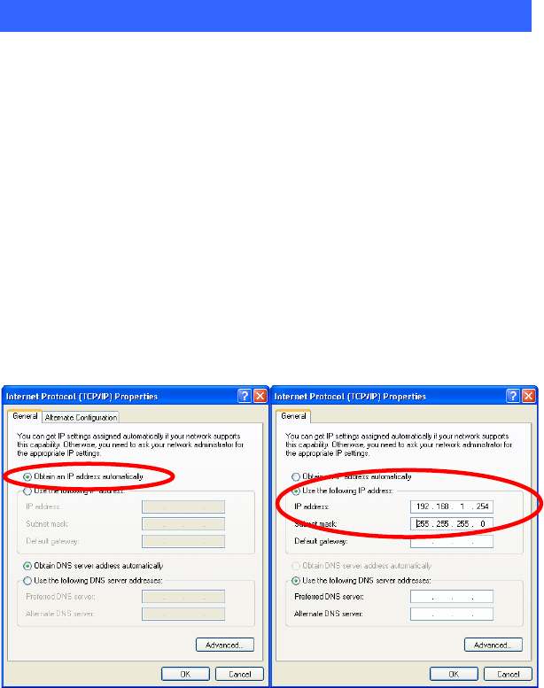
IP Address
Note: When assigning IP Addresses to the computers on the network, remember
to have the IP address for each computer set on the same subnet mask. If your
Broadband Router use DHCP technology, however, it won’t be necessary for you
to assign Static IP Address for your computer.
1. To configure a dynamic IP address (i.e. if your broadband Router has the DHCP
technology), check the Obtain an IP Address Automatically option.
2. To configure a fixed IP address (if you broadband Router is not DHCP
supported, or when you need to assign a static IP address), check the Use the
following IP address option. Then, enter an IP address into the empty field; for
example, enter 192.168.1.254 in the IP address field, and 255.255.255.0 for the
Subnet Mask.
-12 -
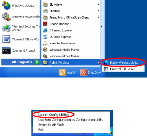
CONFIGURATION UTILITY
After the Wireless adapter has been successfully installed, users can use the
included Configuration Utility to set their preference.
Go to Start
J
(All) Programs
J
Ralink Wireless
J
Ralink Wireless Utility.
You can also open the Configuration Utility by double clicking the icon or right
clicking to select Launch Config Utilities.
-13 -
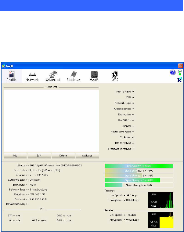
Intelligent Wireless Utility
Profile
Profile can book keeping your favorite wireless setting among your home, office,
and other public hot-spot. You may save multiple profiles, and activate the correct
one at your preference. The Profile manager enables you to Add, Edit, Delete and
Activate profiles.
-14 -
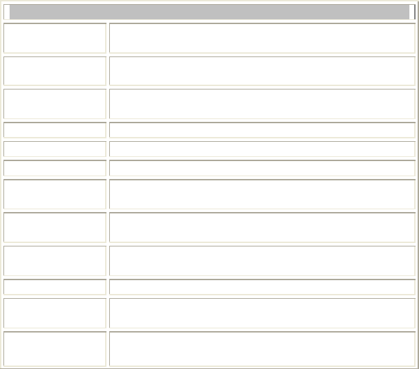
Profile Tab
Profile Name You may enter a distinctive name of profile in this
column. The default is PROF# (# 1, #2, #3....)
SSID The SSID is the unique name shared among all points in
your wireless network.
Network Type Shows the network type of the device, including
infrastructure.
Authentication Shows the authentication mode.
Encryption Shows the encryption type.
Use 802.1x Whether or not use 802.1x feature.
Channel Shows the selected channel that is currently in use. (There
are 13 channels available, depending on the country.)
Power Save
Mode
Choose from CAM (Constantly Awake Mode) or Power
Saving Mode.
Tx Power Transmit power, the amount of power used by a radio
transceiver to send the signal out.
RTS Threshold Shows the RTS Threshold of the device.
Fragment
Threshold Shows the Fragment Threshold of the device.
Add Click to add a profile from the drop-down screen.
System Configuration tab:
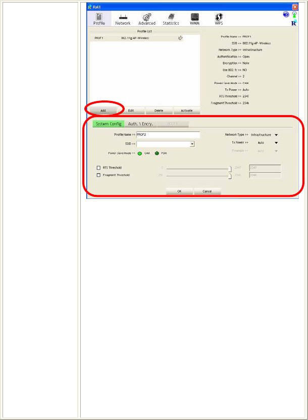
-15 -
Profile Name: User can enter profile name, or use default
name defined by system. The default is PROF# (# 1, #2,
#3....).
SSID: The SSID is the unique name shared among all
points in your wireless network. The name must be
identical for all devices and points attempting to connect
to the same network. User can use pull-down menu to
select from available APs.
Power Save Mode:
xCAM (Constantly Awake Mode): When this mode is
selected, the power supply will be normally provided
even when there is no throughput.
xPSM (Power Saving Mode): When this mode is
selected, this device will stay in power saving mode
even when there is high volume of throughput.
Network Type: There are two types, infrastructure
modes.

-16 -
xThe infrastructure is intended for the connection
between wireless network cards and an Access Point.
With the wireless adapter, you can connect wireless
LAN to a wired global network via an Access Point.
Tx Power: Select the Tx power percentage from the
pull-down list including Auto, 100%, 75%, 50%, 25%,
10% and Lowest.
Preamble: A preamble is a signal used in wireless
environment to synchronize the transmitting timing
including Synchronization and Start frame delimiter.
Select from the pull-down menu to change the Preamble
type into Auto or Long.
RTS Threshold: User can adjust the RTS threshold
number by sliding the bar or key in the value directly. The
default value is 2347. RTS/CTS Threshold is a
mechanism implemented to prevent the “Hidden Node”
problem. If the “Hidden Node” problem is an issue, users
have to specify the packet size. The RTS/CTS mechanism
will be activated if the data size exceeds the value you set.
This value should remain at its default setting of 2347.
Should you encounter inconsistent data flow, only minor
modifications of this value are recommended.
Fragment Threshold: User can adjust the Fragment
threshold number by sliding the bar or key in the value
directly. The default value is 2346. The mechanism of
Fragmentation Threshold is used to improve the
efficiency when high traffic flows along in the wireless
network. If your Wireless LAN Adapter often transmits
large files in wireless network, you can enter new
Fragment Threshold value to split the packet. The value
can be set from 256 to 2346.
-17 -
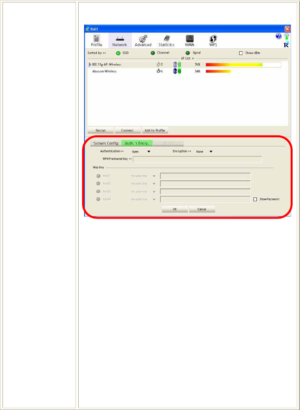
Authentication and Encryption tab:
Authentication Type: There are seven type of
authentication modes including Open, Shared, Leap,
WPA, WPA-PSK, WPA2, WPA2-PSK, and WPA-None.
xOpen: If your access point/wireless router is using
"Open” authentication, then the wireless adapter will
need to be set to the same authentication type.
xShared: Shared Key is when both the sender and the
recipient share a secret key.
xLEAP: Light Extensible Authentication Protocol. It is
an EAP authentication type used primarily in Cisco
Aironet WLANs. It encrypts data transmissions using
dynamically generated WEP keys, and supports mutual
authentication (only with CCX mode enabled.)
xWPA-PSK: WPA-PSK offers two encryption
methods, TKIP and AES. Select the type of algorithm,

-18 -
TKIP or AES and then enter a WPA Shared Key of
8-63 characters in the WPA Pre-shared Key field.
Encryption Type: For open and shared authentication
mode, the selection of encryption type are None and WEP.
For WPA, WPA2, WPA-PSK and WPA2-PSK
authentication mode, the encryption type supports both
TKIP and AES.
WPA Pre-shared Key: This is the shared secret between
AP and STA. For WPA-PSK and WPA2-PSK
authentication mode, this field must be filled with
character longer than 8 and less than 32 length.
WEP Key: Only valid when using WEP encryption
algorithm. The key must match with the AP’s key. There
are several formats to enter the keys.
xHexadecimal (40bits): 10 Hex characters.
xHexadecimal (128bits): 32Hex characters.
xASCII (40bits): 5 ASCII characters.
xASCII (128bits): 13 ASCII characters.
Show Password: Check this box to show the password
you entered.
802.1x Setting: When user use radius server to
authenticate client certificate for WPA authentication
mode.
802.1x tab:
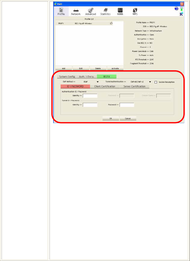
-19 -
EAP Method:
xPEAP: Protect Extensible Authentication Protocol.
PEAP transport securely authentication data by using
tunneling between PEAP clients and an authentication
server. PEAP can authenticate wireless LAN clients
using only server-side certificates, thus simplifying
the implementation and administration of a secure
wireless LAN.
xTLS /Smart Card: Transport Layer Security.
Provides for certificate-based and mutual
authentication of the client and the network. It relies
on client-side and server-side certificates to perform
authentication and can be used to dynamically
generate user-based and session-based WEP keys to
secure subsequent communications between the
WLAN client and the access point.
xTTLS: Tunneled Transport Layer Security. This
security method provides for certificate-based, mutual
authentication of the client and network through an

-20 -
encrypted channel. Unlike EAP-TLS, EAP-TTLS
requires only server-side certificates.
xEAP-FAST: Flexible Authentication via Secure
Tunneling. It was developed by Cisco. Instead of
using a certificate, mutual authentication is achieved
by means of a PAC (Protected Access Credential)
which can be managed dynamically by the
authentication server. The PAC can be provisioned
(distributed one time) to the client either manually or
automatically. Manual provisioning is delivery to the
client via disk or a secured network distribution
method. Automatic provisioning is an in-band, over
the air, distribution. For tunnel authentication, only
support "Generic Token Card" authentication now.
xMD5-Challenge: Message Digest Challenge.
Challenge is an EAP authentication type that provides
base-level EAP support. It provides for only one-way
authentication - there is no mutual authentication of
wireless client and the network.
Tunnel Authentication:
xProtocol: Tunnel protocol, List information including
EAP-MSCHAP v2,EAP-TLS/Smart card, and
Generic Token Card.
xTunnel Identity: Identity for tunnel.
xTunnel Password: Password for tunnel.
Session Resumption: User can click the box to enable or
disable this function.
ID\PASSWORD tab:
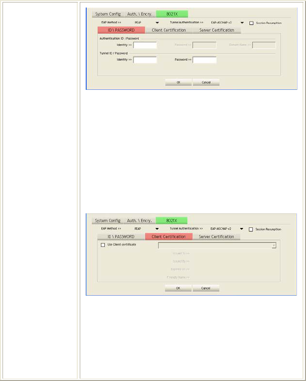
-21 -
ID/ PASSWORD: Identity and password for server.
xAuthentication ID / Password: Identity, password
and domain name for server. Only "EAP-FAST" and
"LEAP" authentication can key in domain name.
Domain name can be keyed in blank space.
xTunnel ID / Password: Identity and Password for
server.
OK: Click to save settings and exit this page.
Cancel: Click to call off the settings and exit.
Client Certification tab:
Client Certification: Client Certicate for server
authentication.
Use Client certification: Choose to enable server
authentication.
OK: Click to save settings and exit this page.
Cancel: Click call off the settings and exit.
Server Certification tab:
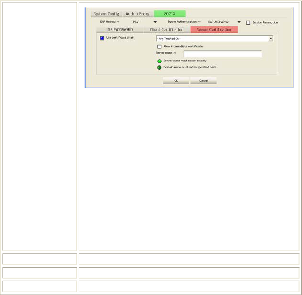
-22 -
Use Certificate chain: Choose use server that issuer of
certificates.
Allow intimidate certificates: It must be in the server
certificate chain between the server certificate and the
server specified in the certificate issuer must be field.
Server name: Enter an authentication sever root.
Server name must match exactly: Click to enable or
disable this function.
Domain name must end in specified name: Click to
enable or disable this function.
OK: Click to save settings and exit this page.
Cancel: Click call off the settings and exit.
Delete Click to delete an existing profile.
Edit Click to edit a profile.
Activate Click to make a connection between devices.
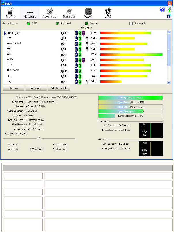
Network
The Network page displays the information of surrounding APs from last scan
result. The tab lists the information including SSID, Network type, Channel,
Wireless mode, Security-Enabled and Signal.
-23 -
Network Tab
Sorted by Indicate that AP list are sorted by SSID, Channel or Signal.
Show dBm Check the box to show the dBm of the AP list.
SSID Shows the name of BSS network.
Network Type Network type in use, Infrastructure for BSS.
Channel Shows the currently used channel.
Wireless mode AP support wireless mode. It may support 802.11a,
802.11b, 802.11g or 802.11n wireless mode.
-24 -
Encryption Shows the encryption type currently in use. Valid value
includes WEP, TKIP, AES, and Not Use.
Signal Shows the receiving signal strength of specified network.
Rescan Click to refresh the AP list.
Connect Select an item on the list and then click to make a
connection.
Add to Profile Select an item on the list and then click to add it into the
profile list.
Link status
Status Shows the current connection status. If there is no
connection existing, it will show Disconnected.
Extra Info Shows the link status.
Channel Shows the current channel in use.
Authentication Authentication mode used within the network, including
Unknown, WPA-PSK, WPA2-PSK, WPA and WPA2.
Encryption Shows the encryption type currently in use. Valid value
includes WEP, TKIP, AES, and Not Use.
Network Type Network type in use, Infrastructure for BSS.
IP Address Shows the IP address information.
Sub Mask Shows the Sub Mask information.
Default
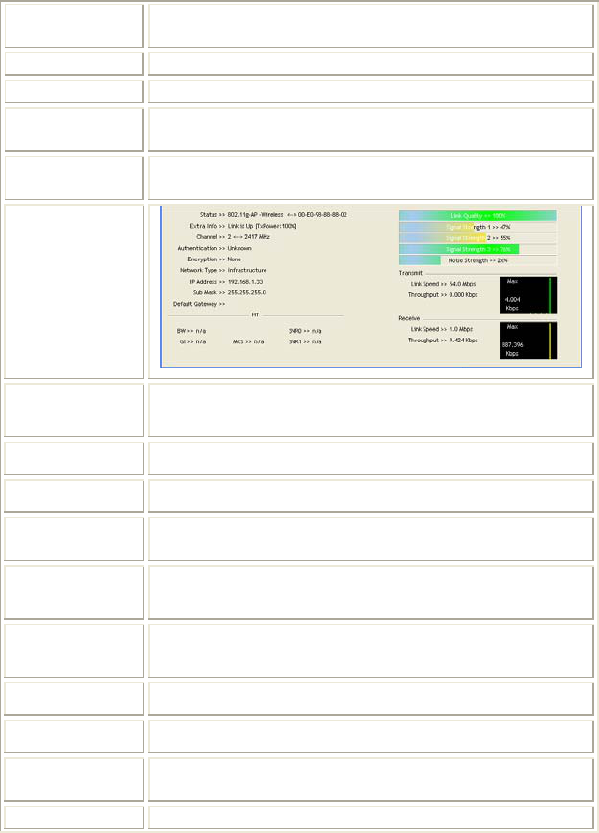
Gateway Shows the default gateway information.
Link Quality Shows the connection quality based on signal strength and
-25 -
TX/RX packet error rate.
Signal
Strength
1, 2 and 3
Shows the Receiving signal strength, you can choose to
display as percentage or dBm format.
Noise Strength Shows the noise signal strength.
Transmit Shows the current Link Speed and Throughput of the
transmit rate.
Receive Shows the current Link Speed and Throughput of receive
rate.
Link Speed Shows the current transmitting rate and receiving rate.
Throughput Shows the transmitting and receiving throughput in the
unit of K bits/sec.
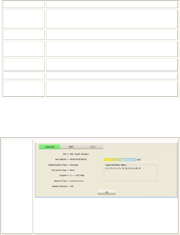
AP information
When you double click on the intended AP, you can see AP's detail information
that divides into three parts. They are General, WPS, CCX information. The
introduction is as following:
General
General information contain AP's SSID, MAC address,
Authentication Type, Encryption Type, Channel, Network Type,
Beacon Interval, Signal Strength and Supported Rates.
OK: Click this button to exit the information screen.
-26 -
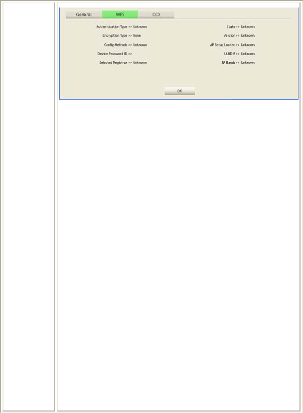
WPS
WPS information contains Authentication Type, Encryption Type,
Config Methods, Device Password ID, Selected Registrar, State,
Version, AP Setup Locked, UUID-E and RF Bands.
Authentication Type: There are four types of authentication
modes supported by RaConfig. They are open, Shared, WPA-PSK
and WPA system.
Encryption Type: For open and shared authentication mode, the
selection of encryption type are None and WEP. For WPA,
WPA2, WPA-PSK and WPA2-PSK authentication mode, the
encryption type supports both TKIP and AES.
Config Methods: Correspond to the methods the AP supports as
an Enrollee for adding external Registrars.
Device Password ID: Indicate the method or identifies the
specific password that the selected Registrar intends to use.
Selected Registrar: Indicate if the user has recently activated a
Registrar to add an Enrollee. The values are "TRUE" and
"FALSE".
State: The current configuration state on AP. The values are
"Unconfigured" and "Configured".
Version: WPS specified version.
AP Setup Locked: Indicate if AP has entered a setup locked state.
UUID-E: The universally unique identifier (UUID) element
generated by the Enrollee. There is a value. It is 16 bytes.
RF Bands: Indicate all RF bands available on the AP. A
dual-band AP must provide it. The values are "2.4GHz" and
"5GHz".
OK: Click this button to exit the information screen.
-27 -
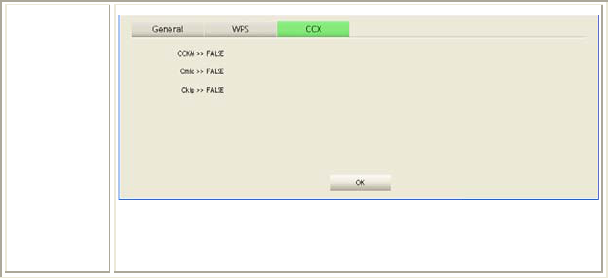
CXX
CCX information contains CCKM, Cmic and Ckip information.
OK: Click this button to exit the information screen.
Advanced
This Advanced page provides advanced and detailed settings for your wireless
network.

-30 -
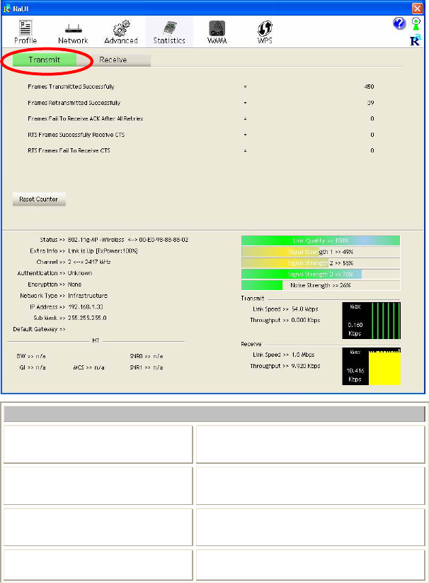
Transmit
Frames Transmitted Successfully Shows information of frames successfully
sent.
Frames Retransmitted
Successfully
Shows information of frames successfully
sent with one or more reties.
Frames Fail To Receive ACK
After All Retries
Shows information of frames failed
transmit after hitting retry limit.
RTS Frames Successfully Receive
CTS
Shows information of successfully receive
CTS after sending RTS frame
-31 -
RTS Frames Fail To Receive
CTS
Shows information of failed to receive CTS
after sending RTS.
Reset Counter Click this button to reset counters to zero.
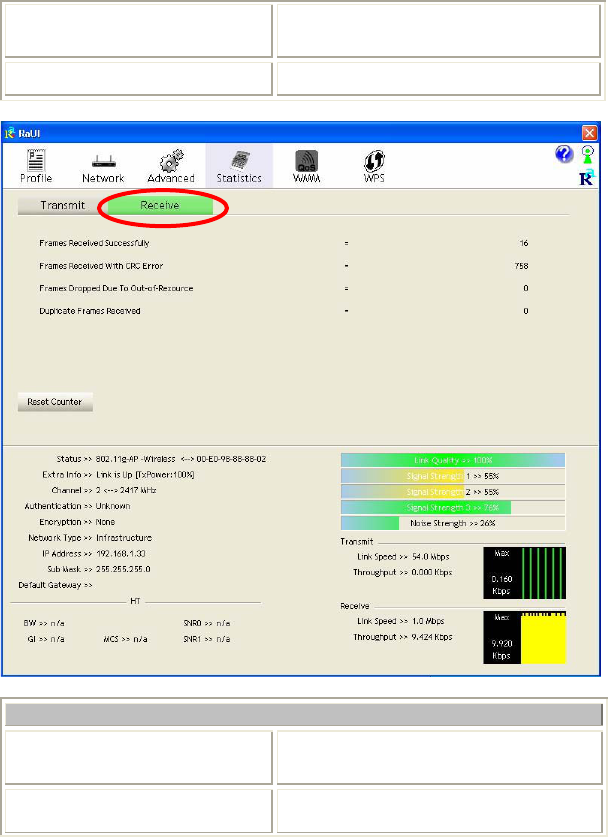
Receive Statistics
Frames Received Successfully Shows information of frames Received
Successfully.
Frames Received With CRC
Error
Shows information of frames received with
-32 -
CRC error.
Frames Dropped Due To
Out-of-Resource
Shows information of frames dropped due
to resource issue.
Duplicate Frames Received Shows information of duplicate received
frames.
Reset Counter Click this button to reset counters to zero.
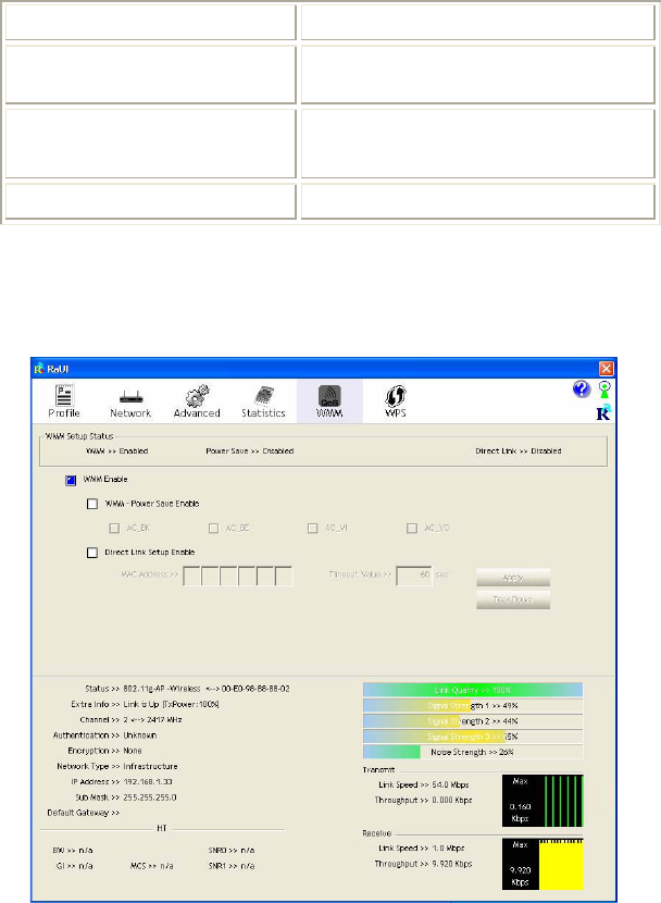
WMM / QoS
The WMM page shows the Wi-Fi Multi-Media power save function and Direct
Link Setup that ensure your wireless network quality.

-33 -
WMM Enable Check the box to enable Wi-Fi Multi-Media
function.
WMM- Power Save Enable Select which ACs you want to enable.
Direct Link Setup Enable Check the box to enable Direct Link Setup.
MAC Address The setting of DLS indicates as follow :
Fill in the blanks of Direct Link with MAC
Address of STA, and the STA must conform to
two conditions:
xConnecting with the same AP that supports
DLS feature.
xDSL enabled.
Timeout Value Timeout Value represents that it disconnect
automatically after few seconds. The value is
integer that must be between 0~65535. It
represents that it always connects if the value is
zero. Default value of Timeout Value is 60
seconds.
Apply Click this button to apply the settings.
Tear Down Select a direct link STA, then click "Tear Down"
button to disconnect the STA.
WPS
The primary goal of Wi-Fi Protected Setup (Wi-Fi Simple Configuration) is to
simplify the security setup and management of Wi-Fi networks. The STA as an
Enrollee or external Registrar supports the configuration setup using PIN
(Personal Identification Number) configuration method or PBC (Push Button
Configuration) method through an internal or external Registrar.
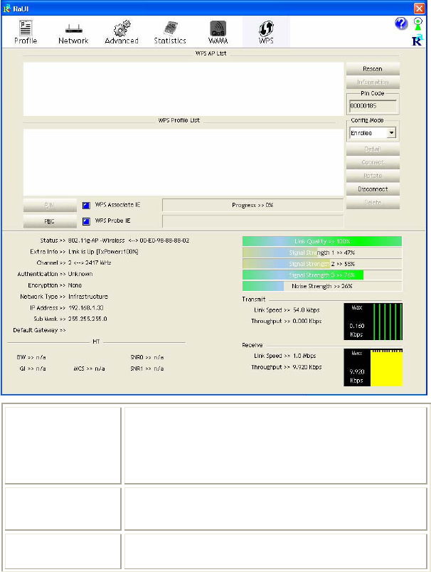
-34 -
WPS AP List Display the information of surrounding APs with WPS IE
from last scan result. List information included SSID,
BSSID, Channel, ID (Device Password ID),
Security-Enabled.
Rescan Issue a rescan command to wireless NIC to update
information on surrounding wireless network.
Information Display the information about WPS IE on the selected
network. List information included Authentication Type,

-35 -
Encryption Type, Config Methods, Device Password ID,
Selected Registrar, State, Version, AP Setup Locked,
UUID-E and RF Bands.
PIN Code 8-digit numbers. It is required to enter PIN Code into
Registrar using PIN method.
Config Mode Our station role-playing as an Enrollee or an external
Registrar.
Detail Information about Security and Key in the credential.
Connect Command to connect to the selected network inside
credentials. The active selected credential is as like as the
active selected Profile.
Rotate Command to rotate to connect to the next network inside
credentials.
Disconnect Stop WPS action and disconnect this active link. And
then select the last profile at the Profile Page. If there is
an empty profile page, the driver will select any
non-security AP.
PIN Start to add to Registrar using PIN (Personal
Identification Number) configuration method. If STA
Registrar, remember that enter PIN Code read from your
Enrollee before starting PIN.
PBC Start to add to AP using PBC (Push Button
Configuration) method.
WPS associate IE Send the association request with WPS IE during WPS
setup. It is optional for STA.
WPS probe IE Send the probe request with WPS IE during WPS setup.
-36 -
It is optional for STA.
Progress Bar Display rate of progress from Start to Connected status.
Status Bar Display currently WPS Status.
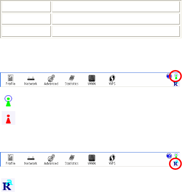
Radio On/Off
Click this icon to turn on radio function.
Click this icon to turn off radio function.
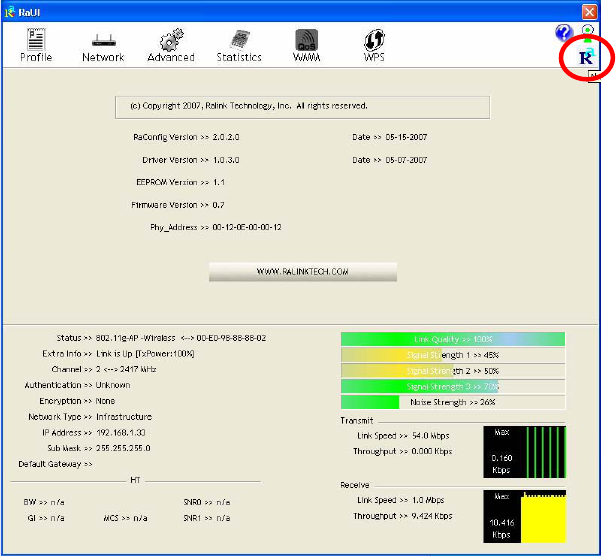
About
Click this button to show the information of the wireless card including,
RaConfig Version/ Date, Driver Version/ Date, EEPROM Version, Firmware
Version and Phy_Address.
-37 -
-38 -
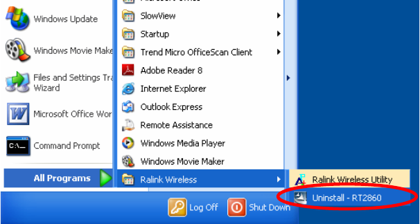
UNINSTALLATION
In case you need to uninstall the utility and driver, please refer to below steps. (As
you uninstall the utility, the driver will be uninstalled as well.)
1. Go to Start
Æ
Programs
Æ
Ralink Wireless
Æ
Uninstall.
-39 -
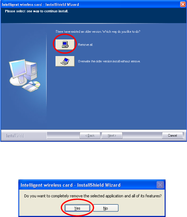
2. Select Remove all button and click Next to start uninstalling.
3. Click Yes to complete remove the selected application and all of its
features.
-40 -
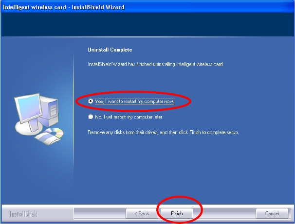
4. Select “Yes, I want to restart my computer now” and then click
Finish to complete the uninstallation.