Quantum Superloader 3 Users Manual ManualsLib Makes It Easy To Find Manuals Online!
2015-01-26
: Quantum Quantum-Superloader-3-Users-Manual-360722 quantum-superloader-3-users-manual-360722 quantum pdf
Open the PDF directly: View PDF ![]() .
.
Page Count: 210 [warning: Documents this large are best viewed by clicking the View PDF Link!]

81-81317-06 A01
SuperLoader™ 3
SuperLoader 3
5SERS'UIDE5SERS'UIDE5SERS'UIDE5SERS'UIDE5SERS'UIDE5SERS'UIDE5SERS'UIDE
Quantum SuperLoader 3 User’s Guide, 81-81317-06 A01, May 2008.
Quantum Corporation provides this publication “as is” without warranty of any kind, either express or
implied, including but not limited to the implied warranties of merchantability or fitness for a particular
purpose. Quantum Corporation may revise this publication from time to time without notice.
COPYRIGHT STATEMENT
Copyright 2008 by Quantum Corporation. All rights reserved.
Your right to copy this manual is limited by copyright law. Making copies or adaptations without prior
written authorization of Quantum Corporation is prohibited by law and constitutes a punishable violation of
the law.
TRADEMARK STATEMENT
Quantum, DLT, DLTtape, The Quantum Logo, and The DLTtape Logo are all registered trademarks of
Quantum Corporation. SuperLoader, SDLT, and Super DLTtape are trademarks of Quantum Corporation.
Other trademarks may be mentioned herein which belong to other companies.

Quantum SuperLoader 3 User’s Guide iii
Contents
Preface xiii
Chapter 1 Introduction 1
Overview............................................................................................................. 1
Host Interfaces ............................................................................................ 2
Tape Drives.................................................................................................. 2
Front Panel................................................................................................... 2
SuperLoader 3 LTO-2................................................................................. 3
SuperLoader 3 LTO-3................................................................................. 3
SuperLoader 3 LTO-4................................................................................. 4
SuperLoader 3 VS160 ................................................................................. 4
SuperLoader 3 DLT-V4.............................................................................. 4
SuperLoader 3 SDLT 600.......................................................................... 5
SuperLoader 3 DLT-S4............................................................................... 5
Chapter 2 Installation and Configuration 6
Installation Overview........................................................................................ 7
SCSI Interface .............................................................................................. 7
Fibre Channel Interface.............................................................................. 8
SAS Interface ............................................................................................... 8

Quantum SuperLoader 3 User’s Guide iv
Choosing a Location ........................................................................................ 10
UL Requirements ............................................................................................. 11
Elevated Operating Ambient Temperature .......................................... 11
Reduced Air Flow..................................................................................... 11
Mechanical Loading ................................................................................. 11
Overloading the Circuit ........................................................................... 11
Reliable Earthing (Grounding) ............................................................... 11
SCSI Bus Requirements................................................................................... 12
Unpacking the Autoloader ............................................................................. 13
Accessories................................................................................................. 14
Rack Mounting the Autoloader ..................................................................... 15
Understanding Autoloader Features ............................................................ 15
General Features ....................................................................................... 15
Connecting Cables ........................................................................................... 18
Connecting SCSI and Power Cables ...................................................... 18
Connecting Fibre Channel and Power Cables...................................... 19
Connecting SAS and Power Cables........................................................ 21
Preparing the Host and Verifying the Connection ..................................... 23
Windows Operating System Support ........................................................... 24
Autoloader Device Driver ....................................................................... 24
Tape Drive Device Driver........................................................................ 24
Bar Code Reader............................................................................................... 26
DLTSage Dashboard........................................................................................ 26
Chapter 3 Operating the Autoloader 27
Operator's Panel Functionality ...................................................................... 27
Enter Passwords........................................................................................ 29
Logout......................................................................................................... 30
Using Cartridges .............................................................................................. 30
Inserting a Single Cartridge .................................................................... 31
Moving a Single Cartridge ...................................................................... 33
Ejecting a Single Cartridge ...................................................................... 33
Using Magazines and Magazine Blanks....................................................... 35
Ejecting a Magazine.................................................................................. 36
Magazine Load/Unload Command ...................................................... 37
Installing a Magazine ............................................................................... 37
Manually Operating the Magazine ........................................................ 38
Viewing Status Information ........................................................................... 41
Viewing SuperLoader 3 Autoloader Status .......................................... 41
Viewing Firmware Version ..................................................................... 42
Viewing Element Status........................................................................... 43

Quantum SuperLoader 3 User’s Guide v
Viewing Tape Drive Status...................................................................... 44
Viewing Tape Drive Version................................................................... 44
Viewing Ethernet Information................................................................ 45
Running an Inventory ..................................................................................... 46
Data Compression............................................................................................ 46
Chapter 4 On-board Remote Management 47
On-board Remote Management Overview.................................................. 47
Opening On-board Remote Management............................................. 48
Viewing Status Information .................................................................... 49
Default Username and Password........................................................... 49
Time Display ............................................................................................. 49
Feedback on Pages.................................................................................... 50
Configurations Page ........................................................................................ 50
System Operations Options..................................................................... 50
Updates Page.................................................................................................... 61
Diagnostics Page .............................................................................................. 62
Running Diagnostic Tests........................................................................ 62
Viewing Error or History Logs ............................................................... 62
Diagnostics................................................................................................. 63
Identification.............................................................................................. 63
Performing a System Reset...................................................................... 63
Commands Page .............................................................................................. 64
Inventory.................................................................................................... 64
Set to Home ............................................................................................... 64
Sequential Operations.............................................................................. 65
Chapter 5 Administration 66
Introduction ...................................................................................................... 67
Configuring the Autoloader........................................................................... 68
SCSI Autoloader........................................................................................ 70
SAS Autoloader......................................................................................... 70
Fibre Channel Autoloader....................................................................... 71
Setting Ethernet................................................................................................ 72
Setting the IP Address.............................................................................. 72
Setting the Subnet Mask .......................................................................... 73
Setting an IP Gateway .............................................................................. 74
System Time .............................................................................................. 74

Quantum SuperLoader 3 User’s Guide vi
Setting the Time Zone .............................................................................. 74
Setting the Date and Time ....................................................................... 75
Setting the Change Mode................................................................................ 76
Sequential Mode Operations................................................................... 77
Setting Security................................................................................................. 78
Setting Magazines ............................................................................................ 79
Setting Passwords ............................................................................................ 79
Getting Lost Passwords ........................................................................... 80
Chapter 6 Diagnostics 81
Power-on Self Test (POST).............................................................................. 82
Performing a POST................................................................................... 83
Interpreting the POST Results ................................................................ 83
Diagnostic Tests from the Front Panel.......................................................... 84
Setting the Security................................................................................... 84
Stopping a Diagnostic Test...................................................................... 85
Front Panel Diagnostic Tests................................................................... 86
On-board Remote Management Diagnostic Tests ...................................... 87
Diagnostics Using On-board Remote Management............................ 87
Chapter 7 Customer Replaceable Units (CRUs) 88
Replacing a Magazine or Magazine Blank ................................................... 88
Removing a Magazine.............................................................................. 89
Removing a Magazine Blank .................................................................. 89
Reinstalling a Magazine........................................................................... 90
Installing a Magazine Blank.................................................................... 90
Changing the Orientation........................................................................ 90
Rack Mounting the Autoloader ..................................................................... 93
General Preparation for Rack Mount Installation................................ 95
Stationary Rack Mount Installation ....................................................... 95
Chapter 8 Logs and Troubleshooting 102
Before Contacting Customer Support......................................................... 102
Autoloader Logs............................................................................................. 106
Log Types................................................................................................. 107
Retrieving the Hard Log........................................................................ 108

Quantum SuperLoader 3 User’s Guide vii
Hard Log Example.................................................................................. 109
Time Stamp.............................................................................................. 110
Error Fields .............................................................................................. 111
Tape Drive Logs ............................................................................................. 120
Log Fields................................................................................................. 120
POST Failure Logs ......................................................................................... 121
Returning the Autoloader for Service......................................................... 122
Preparing the Autoloader for Shipment.............................................. 122
Removing the Autoloader from a Rack............................................... 122
Packing the Autoloader ......................................................................... 123
Appendix A Specifications 124
Autoloader Specifications............................................................................. 125
Autoloader Performance Specifications ..................................................... 126
Autoloader Environmental Specifications ................................................. 129
Autoloader Power Specifications ................................................................ 130
Autoloader Vibration Specifications........................................................... 130
Autoloader Shock Specifications ................................................................. 131
Tape Drive Specifications ............................................................................. 131
LTO-2 Drive Specifications........................................................................... 132
Media Capacity ....................................................................................... 132
Media Specifications............................................................................... 132
LTO-3 Drive Specifications........................................................................... 134
Media Capacity ....................................................................................... 134
Media Specifications............................................................................... 134
LTO-4 Drive Specifications........................................................................... 136
Media Capacity ....................................................................................... 136
Media Specifications............................................................................... 136
VS160 Drive Specifications ........................................................................... 138
Media Capacity ....................................................................................... 138
Media Specifications............................................................................... 138
DLT-V4 Drive Specifications........................................................................ 140
Media Capacity ....................................................................................... 140
Media Specifications............................................................................... 140
SDLT 600 Drive Specifications..................................................................... 142
Media Capacity ....................................................................................... 142
Media Specifications............................................................................... 142
DLT-S4 Drive Specifications......................................................................... 144
Media Capacity ....................................................................................... 144
Media Specifications............................................................................... 144

Quantum SuperLoader 3 User’s Guide viii
Appendix B Drive Error Logs 146
Tape Drive Error Logs................................................................................... 146
Error Log Display ................................................................................... 146
SCSI Check Condition Error Logs........................................................ 147
Bugcheck Error Logs (SDLT 600 only)........................................................ 150
Event Error Logs (SDLT 600 only)............................................................... 152
A500: Hard Read Error .......................................................................... 152
A501: SDLT Hard Write Error .............................................................. 155
A502: SDLT Loader Communication Error ........................................ 157
A503: SDLT Drive Servo Error.............................................................. 158
A507/A508: Directory Read Failure/Directory Write Failure......... 163
Appendix C Regulatory Statements 170
FCC Statement................................................................................................ 170
Taiwan Statement .......................................................................................... 171
Japan Notice.................................................................................................... 171
Canadian Notice (Avis Canadien)............................................................... 171
European Union Notice ................................................................................ 172
Product Safety Electrostatic Discharge ....................................................... 172
Grounding Methods ...................................................................................... 173
Environmental Compliance.......................................................................... 173
Disposal of Electrical and Electronic Equipment ..................................... 174
Glossary 175
Index 188

Quantum SuperLoader 3 User’s Guide ix
Figures
Figure 1 Front Panel Overview................................................................ 16
Figure 2 Back Panel Overview................................................................. 17
Figure 3 Cable Connectors (SCSI Tape Drive)....................................... 18
Figure 4 Cable Connectors (Fibre Channel Tape Drive)...................... 20
Figure 5 Cable Connectors (SAS Tape Drive)........................................ 21
Figure 6 Front Panel .................................................................................. 28
Figure 7 Left Magazine ............................................................................. 35
Figure 8 System Menu Tree...................................................................... 69
Figure 9 Left Magazine ............................................................................. 91
Figure 10 Removing the Screws from the Handle .................................. 92
Figure 11 Clearance Requirements for Rack Mounting......................... 94
Figure 12 Required Parts for Installation ................................................. 96
Figure 13 Installing Two Clip Nuts........................................................... 97
Figure 14 Attaching Autoloader Brackets................................................ 98
Figure 15 Attaching Support Brackets...................................................... 99
Figure 16 Sliding Autoloader into Rack ................................................. 100
Figure 17 Front Alignment....................................................................... 100
Quantum SuperLoader 3 User’s Guide x
Figure 18 Connecting Support Brackets ................................................. 101
Figure 19 POST Failures Event Log Sample .......................................... 121

Quantum SuperLoader 3 User’s Guide xi
Tables
Table 1 Location Criteria......................................................................... 10
Table 2 Front Panel LEDs........................................................................ 29
Table 3 Autoloader Status....................................................................... 42
Table 4 Firmware Version Fields........................................................... 43
Table 5 Drive Status Fields ..................................................................... 44
Table 6 Drive Version Fields .................................................................. 45
Table 7 Ethernet Information Fields...................................................... 45
Table 8 POST Descriptions ..................................................................... 82
Table 9 Probable Cause and Possible Solutions ................................ 103
Table 10 Log Retrieval Methods ............................................................ 108
Table 11 Error Type Listing and Suggested Actions .......................... 113
Table 12 Log Field Descriptions............................................................. 120
Table 13 POST Failure Specific Fields................................................... 121
Table 14 Error Log Display Field Descriptions ................................... 147
Table 15 SCSI Check Condition Error Log Field Descriptions.......... 147
Table 16 Sense Key Field Definitions .................................................... 148
Table 17 ASC/ASCQ Field Descriptions.............................................. 149
Quantum SuperLoader 3 User’s Guide xii
Table 18 Bugcheck Log Field Descriptions........................................... 151
Table 19 Error Event Logs Field Descriptions ..................................... 152
Table 20 Hard Read Error/Hard Write Error Block Descriptor ....... 153
Table 21 Hard Read /Hard Write Error Field Descriptions .............. 153
Table 22 Hard Read Error/Hard Write Error Block Descriptor ....... 155
Table 23 Hard Read Error/Hard Write Error Field Descriptions..... 155
Table 24 Loader Communication Error Block Description................ 157
Table 25 Loader Communication Error Field Description................. 157
Table 26 Drive Servo Error Block Descriptor....................................... 158
Table 27 Drive Servo Error Field Descriptions .................................... 158
Table 28 Directory Read Failure/Write Failure Block Descriptor .... 163
Table 29 Directory Read/Write Failure Field Descriptions............... 164

Quantum SuperLoader 3 User’s Guide xiii
Preface
This document serves as an easy-to-use information source to familiarize
Quantum customers and systems professionals with the SuperLoader 3
autoloader.
Audience The primary audience for this document consists of end users installing
and using the SuperLoader 3 autoloader.
Purpose This document provides information on the SuperLoader 3 including:
• Product description
• Installation instructions
• Operation instructions
• Remote as well as front-panel administration of the autoloader
• Diagnostics
• Customer Replaceable Unit (CRU) procedures
• System log files as well as error logs
• Troubleshooting
• Specifications
• Regulatory compliance and statements

Preface
Quantum SuperLoader 3 User’s Guide xiv
Document Organization This document is organized as follows:
•Chapter 1, Introduction, provides a brief product overview.
•Chapter 2, Installation and Configuration, describes a typical
installation, SCSI bus requirements, accessories, selecting a location
for the autoloader, UL requirements, features and a product
overview as well as a product components identification, the bar
code reader, identifying product components, SCSI (or Fibre Channel
or SAS) and power cable connection, preparing the host and
verifying the connection, and installing device drivers.
•Chapter 3, Operating the Autoloader, provides information about
Operator Control Panel functionality, using cartridges, magazines
and magazine blanks, viewing status information, running an
inventory and data compression.
•Chapter 4, On-board Remote Management, provides an On-board
Remote Management overview, including the Configurations,
Updates, Diagnostics and Commands pages.
•Chapter 5, Administration, describes configuring the autoloader,
setting the SCSI ID, Ethernet, time, change mode, security,
magazines, and passwords.
•Chapter 6, Diagnostics, provides POST information and diagnostic
test information using the front panel and On-board Remote
Management.
•Chapter 7, Customer Replaceable Units (CRUs), includes information
about components you can service yourself.
•Chapter 8, Logs and Troubleshooting, provides log descriptions,
troubleshooting information, and information on returning the
autoloader for service.
•Appendix A, Specifications, provides autoloader and tape drive
specifications.
•Appendix B, Drive Error Logs, lists tape drive errors and SCSI check
condition error logs, as well as bugcheck and event error logs for the
SDLT 600 only.
•Appendix C, Regulatory Statements, lists the applicable regulatory
statements for the autoloader.
This document concludes with a glossary and index.

Preface
Quantum SuperLoader 3 User’s Guide xv
Notational Conventions This document uses the following conventions:
• Right side of the autoloader — Refers to the right side as you face the
component being described.
• Left side of the autoloader — Refers to the left side as you face the
component being described.
• Power cycle — Means to turn the autoloader or system on, then turn
them off (or off, then on).
• Dimensions in figures — All dimensions are shown with no units
specified (Inches understood unless otherwise specified).
Related Documentation Documents related to the Quantum SuperLoader 3 are shown below:
Note: Notes emphasize important information related to the main
topic.
Caution: Cautions indicate potential hazards to equipment and are
included to prevent damage to equipment.
Warning: Warnings indicate potential hazards to personal safety and
are included to prevent injury.
Document No. Document Title Document Description
81-81313 Quantum
SuperLoader 3
Quick Start Guide
This guide contains a
sequence of steps
recommended for unpacking,
installing, and setting up
your autoloader.
81-81237 How to Ship the
Quantum
SuperLoader
This guide provides
information on the proper
packing for returning the
autoloader for repair.

Preface
Quantum SuperLoader 3 User’s Guide xvi
SCSI-2 Specification 0
The SCSI-2 communications specification is the proposed American
National Standard for information systems, dated March 9, 1990. Copies
may be obtained from:
Global Engineering Documents
15 Inverness Way, East
Englewood, CO 80112
(800) 854-7179 or (303) 397-2740
Contacts Quantum company contacts are listed below.
Quantum Corporate Headquarters 0
To order documentation on the SuperLoader 3 Autoloader or other
products, contact:
Quantum Corporation (Corporate Headquarters)
1650 Technology Drive, Suite 700
San Jose, CA 95110-1382
Technical Publications 0
To comment on existing documentation send e-mail to:
doc-comments@quantum.com
Quantum Home Page 0
Visit the Quantum home page at:
www.quantum.com

Preface
Quantum SuperLoader 3 User’s Guide xvii
Getting More Information or
Help StorageCare™, Quantum’s comprehensive service approach, leverages
advanced data access and diagnostics technologies with cross-
environment, multi-vendor expertise to resolve backup issues faster and
at lower cost.
Accelerate service issue resolution with these exclusive Quantum
StorageCare services:
•Service and Support Website - Register products, license software,
browse Quantum Learning courses, check backup software and
operating system support, and locate manuals, FAQs, firmware
downloads, product updates and more in one convenient location.
Benefit today at: www.quantum.com/support.
•eSupport - Submit online service requests, update contact
information, add attachments, and receive status updates via email.
Online Service accounts are free from Quantum. That account can
also be used to access Quantum’s Knowledge Base, a comprehensive
repository of product support information. Sign up today at:
www.quantum.com/support.
For further assistance, or if training is desired, contact Quantum
Technical Assistance Center:
North America: +1-800-284-5101
UK, France and Germany 00800 4 QUANTUM
EMEA +44 1256 848 766
For worldwide support: www.quantum.com/contactsupport
For the most up to date information on Quantum Global Services, please
visit www.quantum.com/support.
Preface
Quantum SuperLoader 3 User’s Guide xviii

Quantum SuperLoader 3 User’s Guide 1
Chapter 1
1Introduction
Overview
Data backup is essential to protect irreplaceable information. Backing up
data to magnetic tape is an easy, cost-efficient method used by many
small and medium businesses. However, most enterprises have so much
data that a single backup tape is not enough; the information has to be
spread across numerous tapes. To avoid constantly changing tapes
manually, many tape backup systems include a Quantum SuperLoader 3
autoloader.
Each autoloader is a robot that includes a tape drive and one or two
magazines for tape cartridges. The user's application can automatically
load and unload tape cartridges as required for data backup or data
retrieval. Quantum SuperLoader 3 autoloaders provide a compact, high
capacity, but low cost method for simple, unattended data backup.

Chapter 1 Introduction
Overview
Quantum SuperLoader 3 User’s Guide 2
Host Interfaces 1The Quantum SuperLoader 3 connects to your host server via a SCSI,
Fibre Channel, or Serial Attached SCSI (SAS) connection allowing the
host to send data and commands automatically. You can also connect to
the autoloader using an Ethernet connection to perform administrative
functions and download system updates.
Tape Drives 1Your Quantum SuperLoader 3 contains one of the following tape drives
and one or two magazines capable of containing up to eight tape
cartridges each.
•SuperLoader 3 LTO-2 (SCSI)
•SuperLoader 3 LTO-3 (SCSI, Fibre Channel, or SAS)
•SuperLoader 3 LTO-4 (SCSI or SAS)
•SuperLoader 3 VS160 (SCSI)
•SuperLoader 3 DLT-V4 (SCSI)
•SuperLoader 3 SDLT 600 (SCSI)
•SuperLoader 3 DLT-S4 (SCSI or Fibre Channel)
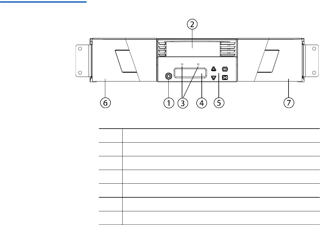
Front Panel 1The front panel on the autoloader includes a liquid crystal display (LCD)
screen and four function keys. A scrolling menu on the LCD screen
allows you to obtain information from the autoloader and enter
commands. The front panel also includes two light emitting diodes
(LEDs) indicating the autoloader's ready status and error status.
A single tape cartridge can be inserted directly into the tape drive via a
password-protected mailslot on the front panel (provided there is no
cartridge already in the drive). You can also load a tape cartridge into a
magazine slot (provided there is no cartridge already in the slot).

Chapter 1 Introduction
Overview
Quantum SuperLoader 3 User’s Guide 3
SuperLoader 3 LTO-2 1This autoloader is SCSI-3 compatible and operates as a single SCSI ID/
two LUN data storage device.
The Quantum SuperLoader 3 LTO-2 autoloader is equipped with a
Quantum LTO-2 tape drive and contains up to sixteen Ultrium 2 data
cartridges when utilizing two magazines, providing a compressed
capacity of 6.4 Terabytes and a sustained data transfer rate of 93.6 GB per
hour (native) or as high as 187.2 GB per hour compressed (assuming 2:1
compression).
The autoloader is compatible with the most popular operating systems
and environments supporting a Ultra 160 SCSI-3 LVD interface but
requires direct support from the operating system or a compatible
backup application to take full advantage of its many features.
SuperLoader 3 LTO-3 1This autoloader is SCSI-3 compatible and operates as a single SCSI ID/
two LUN data storage device. It is also available as a Fibre Channel or
Serial Attached SCSI (SAS) data storage device.
The Quantum SuperLoader 3 autoloader is equipped with a LTO-3 tape
drive and contains up to sixteen Ultrium 3 data cartridges when utilizing
two magazines, providing a compressed capacity of 12.8 Terabytes and a
sustained data transfer rate of 245 GB per hour (native) or as high as
490 GB per hour compressed (assuming 2:1 compression).
The autoloader is compatible with the most popular operating systems
and environments supporting a Ultra 160 SCSI-3 LVD interface but
requires direct support from the operating system or a compatible
backup application to take full advantage of its many features.
Fibre Channel can support up to 126 devices in a loop configuration.
Longwave transceivers (with Fibre Channel cable) support distances up
to 10 kilometers; short pulsewave transceivers (with Fibre Channel cable)
support distances up to 500 meters.
The Fibre Channel version of the SuperLoader 3 LTO-3 operates at speeds
up to 2 Gigabits (Gb)/second.

Chapter 1 Introduction
Overview
Quantum SuperLoader 3 User’s Guide 4
SuperLoader 3 LTO-4 1This autoloader is SCSI-3 compatible and operates as a single SCSI ID/
two LUN data storage device. It is also available as a Serial Attached SCSI
(SAS) data storage device.
The Quantum SuperLoader 3 autoloader is equipped with a LTO-4 tape
drive and contains up to sixteen Ultrium 4 data cartridges when utilizing
two magazines, providing a compressed capacity of 25.6 Terabytes and a
sustained data transfer rate of 432 GB per hour (native) or as high as
864 GB per hour compressed (assuming 2:1 compression).
The autoloader is compatible with the most popular operating systems
and environments supporting a Ultra 320 SCSI-3 LVD interface but
requires direct support from the operating system or a compatible
backup application to take full advantage of its many features.
SuperLoader 3 VS160 1This autoloader is SCSI-3 compatible and operates as a single SCSI ID/
two LUN data storage device.
The Quantum SuperLoader 3 VS160 autoloader is equipped with a
Quantum VS160 tape drive and contains up to sixteen Quantum VS1 data
cartridges when utilizing two magazines, providing a compressed
capacity of 2.5 TB and a sustained data transfer rate of 28.8 GB per hour
(native) or as high as 57.6 GB per hour compressed (assuming 2:1
compression).
The autoloader is compatible with the most popular operating systems
and environments supporting a SCSI LVD interface but requires direct
support from the operating system or a compatible backup application to
take full advantage of its many features.
SuperLoader 3 DLT-V4 1This autoloader is SCSI-3 compatible and operates as a single SCSI ID/
two LUN data storage device.
The Quantum SuperLoader 3 autoloader DLT-V4 is equipped with a
Quantum DLT-V4 tape drive and contains up to sixteen DLT VS1 data
cartridges when utilizing two magazines, providing a compressed
capacity of 5.1 Terabytes and a sustained data transfer rate of 36 GB per
hour (native) or as high as 72 GB per hour compressed (assuming 2:1
compression).
The autoloader is compatible with the most popular operating systems
and environments supporting a Ultra 160 SCSI-3 LVD interface but
requires direct support from the operating system or a compatible
backup application to take full advantage of its many features.

Chapter 1 Introduction
Overview
Quantum SuperLoader 3 User’s Guide 5
SuperLoader 3 SDLT 6001This autoloader is SCSI-3 compatible and operates as a single SCSI ID/
two LUN data storage device.
The Quantum SuperLoader 3 SDLT 600 autoloader is equipped with a
Quantum SDLT 600 tape drive and contains up to sixteen SDLT II data
cartridges when utilizing two magazines, providing a compressed
capacity of 9.4 Terabytes and a sustained data transfer rate of 129.6 GB
per hour (native) or as high as 259.2 GB per hour compressed (assuming
2:1 compression).
The autoloader is compatible with the most popular operating systems
and environments supporting a 16-bit Ultra 160 SCSI-3 LVD interface but
requires direct support from the operating system or a compatible
backup application to take full advantage of its many features.
SuperLoader 3 DLT-S4 1This autoloader is SCSI-3 compatible and operates as a single SCSI ID/
two LUN data storage device. It is also available as a Fibre Channel data
storage device.
The Quantum SuperLoader 3 DLT-S4 autoloader is equipped with a
Quantum DLT-S4 tape drive and contains up to sixteen DLTtape S4 data
cartridges when utilizing two magazines, providing a compressed
capacity of 25.6 Terabytes and a sustained data transfer rate of 216 GB per
hour (native) or as high as 432 GB per hour compressed (assuming 2:1
compression).
The autoloader is compatible with the most popular operating systems
and environments supporting an Ultra 320 SCSI-3 LVD interface but
requires direct support from the operating system or a compatible
backup application to take full advantage of its many features.
Fibre Channel can support up to 126 devices in a loop configuration.
Longwave transceivers (with Fibre Channel cable) support distances up
to 10 kilometers; short pulsewave transceivers (with Fibre Channel cable)
support distances up to 500 meters.
The Fibre Channel version of the SuperLoader 3 DLT-S4 operates at
speeds up to 4 Gigabits (Gb)/second.

Quantum SuperLoader 3 User’s Guide 6
Chapter 2
2Installation and Configuration
This chapter covers all aspects of installing the autoloader in your
location. The following information is available:
•“Installation Overview” on page 7
•“Choosing a Location” on page 10
•“UL Requirements” on page 11
•“SCSI Bus Requirements” on page 12
•“Unpacking the Autoloader” on page 13
•“Rack Mounting the Autoloader” on page 15
•“Understanding Autoloader Features” on page 15
•“Front Panel Overview” on page 16
•“Back Panel Overview” on page 17
•“Connecting Cables” on page 18
•“Preparing the Host and Verifying the Connection” on page 23
•“Windows Operating System Support” on page 24
•“Bar Code Reader” on page 26
•“DLTSage Dashboard” on page 26

Chapter 2 Installation and Configuration
Installation Overview
Quantum SuperLoader 3 User’s Guide 7
Installation Overview
The SuperLoader 3 is a SCSI device that interfaces to your host computer
(see SCSI Interface).
A Fibre Channel version of the autoloader is available when equipped
with a LTO-3 or DLT-S4 native Fibre Channel tape drive (see Fibre
Channel Interface).
A Serial Attached SCSI (SAS) version of the autoloader is available when
equipped with a LTO-3 or LTO-4 SAS tape drive (see SAS Interface).
SCSI Interface 2Installing the SCSI autoloader consists of the following steps, which are
explained in more detail later in this section:
1Prepare to install your new Quantum SuperLoader 3 autoloader (see
“Choosing a Location” on page 10).
2Identify the proper SCSI bus types (see “SCSI Bus Requirements” on
page 12).
3Identify the accessories that come with the autoloader (see
“Accessories” on page 14).
4Install the autoloader in a computer rack or select a table or desktop
near the host server. If installing a rack mount unit, refer to “Rack
Mounting the Autoloader” on page 93.
5Shut down or turn off the server and all devices attached to the
server.
6Attach the SCSI cable to the autoloader and server's SCSI host
adapter (see “Connecting SCSI and Power Cables” on page 18).
7Attach the power cable to the autoloader and plug in the power cable
to the nearest power outlet (see “Connecting SCSI and Power Cables”
on page 18). Power the autoloader on to ensure it passes the power
on self-test (POST).
8Set the SCSI ID for the autoloader (see “SCSI Autoloader” on
page 70).
9Set up the host and verify the connection (see “Preparing the Host
and Verifying the Connection” on page 23).

Chapter 2 Installation and Configuration
Installation Overview
Quantum SuperLoader 3 User’s Guide 8
10 Install the device drivers (see “Windows Operating System Support”
on page 24.
Fibre Channel Interface 2Installing the Fibre Channel autoloader consists of the following steps,
which are explained in more detail later in this section:
1Prepare to install your new Quantum SuperLoader 3 autoloader (see
“Choosing a Location” on page 10).
2Identify the accessories that come with the autoloader (see
“Accessories” on page 14).
3Install the autoloader in a computer rack or select a table or desktop
near the host server. If installing a rack mount unit, refer to “Rack
Mounting the Autoloader” on page 93.
4Attach the Fibre Channel cable to the autoloader and a Fibre Channel
switch or the server's Fibre Channel host adapter (see “Connecting
Fibre Channel and Power Cables” on page 19).
5Attach the power cable to the autoloader and plug in the power cable
to the nearest power outlet (see “Connecting Fibre Channel and
Power Cables” on page 19). Power the autoloader on to ensure it
passes the power on self-test (POST).
6Install the device drivers (see “Windows Operating System Support”
on page 24).
SAS Interface 2Installing the Serial Attached SCSI (SAS) autoloader consists of the
following steps, which are explained in more detail later in this section:
1Prepare to install your new Quantum SuperLoader 3 autoloader (see
“Choosing a Location” on page 10).
2Identify the accessories that come with the autoloader (see
“Accessories” on page 14).
3Install the autoloader in a computer rack or select a table or desktop
near the host server. If installing a rack mount unit, refer to “Rack
Mounting the Autoloader” on page 93.
4Attach the SAS cable to the autoloader and a Fibre Channel switch or
the server's Fibre Channel host adapter (see “Connecting SAS and
Power Cables” on page 21).

Chapter 2 Installation and Configuration
Installation Overview
Quantum SuperLoader 3 User’s Guide 9
5Attach the power cable to the autoloader and plug in the power cable
to the nearest power outlet (see “Connecting SAS and Power Cables”
on page 21). Power the autoloader on to ensure it passes the power
on self-test (POST).
6Install the device drivers (see “Windows Operating System Support”
on page 24).

Chapter 2 Installation and Configuration
Choosing a Location
Quantum SuperLoader 3 User’s Guide 10
Choosing a Location
The autoloader is designed to fit in a standard 19-inch rack using either
the long or short brackets (depending on the depth of the rack). Choose a
location that meets the following criteria (see appendix A, Specifications).
The autoloader uses standard rack mounting hardware.
Table 1 Location Criteria
Criteria Description
Rack requirements Standard 19-inch rack with 2U of clearance.
Room temperature 10–35° C (50–95° F)
Power source AC power voltage: 100–127 VAC; 200–240 VAC
Line frequency: 50–60 Hz
Note: Locate the AC outlet near the autoloader. The AC power cable is the
product’s main disconnect device and must be easily accessible at all
times.
Weight 14.1 kg (31 lb) unloaded
17.2 kg (38 lb) loaded with 2 magazines, 16 cartridges
Air Quality Minimize sources of particulate contamination. Avoid areas near frequently
used doors and walkways, cooling or exhaust vents, stacks of supplies that
collect dust, printers, and smoke-filled rooms.
Caution: Excessive dust and debris can damage tapes and tape drives.
Humidity 20–80% RH (non-condensing)
Clearance Back: Minimum of 43.2 cm (17 in.)
Front: Minimum of 68.6 cm (27 in.)
Sides: Minimum of 5.08 cm (2 in.)

Chapter 2 Installation and Configuration
UL Requirements
Quantum SuperLoader 3 User’s Guide 11
UL Requirements
Elevated Operating
Ambient Temperature 2When installed in a closed multi-unit rack assembly, the operating
ambient temperature of the rack environment may be greater than the
room ambient. Therefore, consideration should be given to installing the
equipment in an environment compatible with the manufacturer’s
maximum recommended ambient temperature.
Reduced Air Flow 2Installation of the equipment in a rack should be such that the amount of
air flow required for safe operation of the equipment is not compromised.
Mechanical Loading 2Mounting of the equipment in a rack should be such that a hazardous
condition is not achieved due to uneven mechanical loading.
Overloading the Circuit 2Consideration should be given to the connection of the equipment to the
supply circuit and the effect that overloading of circuits might have on
overcurrent protection and supply wiring. Appropriate consideration of
equipment nameplate ratings should be used when addressing the
concern.
Reliable Earthing
(Grounding) 2Reliable earthing of rack-mounted equipment should be maintained.
Particular attention should be given to supply connections other than
direct connections to the branch circuit, such as use of power strips.

Chapter 2 Installation and Configuration
SCSI Bus Requirements
Quantum SuperLoader 3 User’s Guide 12
SCSI Bus Requirements
There are minor differences between the Quantum SuperLoader 3 LTO-2
and the Quantum SuperLoader 3 VS160/SDLT 600 autoloaders.
SuperLoader 3 LTO-2 2
You must connect the Quantum SuperLoader 3 LTO-2 to one of the
following SCSI bus types:
• Ultra2 SCSI Low-voltage Differential (LVD), Single-ended (SE) SCSI
bus
SuperLoader 3 VS160/SDLT 600 2
You must connect the Quantum SuperLoader 3 VS160 or the Quantum
SuperLoader 3 SDLT 600 to one of the following SCSI bus types:
• Ultra 320 SCSI-3, LVD SE SCSI bus
• Ultra 160 SCSI-3, LVD SE SCSI bus
General Information 2
Your SCSI host adapter card must also support the SCSI bus type used to
connect the autoloader. If you use a LVD SCSI bus, use a host adapter
card with a connection for a high-density (HD) 68-pin cable.
Note: The autoloader is not compatible with a High-voltage
Differential (HVD) SCSI bus.
Note: If you use a single-ended (SE) SCSI bus, the tape drive’s
performance is limited to the maximum data transfer speed of
the bus.
Note: The maximum number of autoloaders supported per SCSI bus
is two.

Chapter 2 Installation and Configuration
Unpacking the Autoloader
Quantum SuperLoader 3 User’s Guide 13
Unpacking the Autoloader
Before you begin, clear a desk or table so that you have room to unpack
the autoloader. Ensure that the work area is free from conditions that
could cause electrostatic discharge (ESD). Discharge static electricity from
your body by touching a known grounded surface, such as your
computer's metal chassis.
The Quantum SuperLoader 3 Quick Start Guide included in the packaging
describes how to unpack and inspect your autoloader correctly. Please
locate the Quantum SuperLoader 3 Quick Start Guide and follow the
directions.
Unpack your new Quantum SuperLoader 3 autoloader carefully and
inspect it for any damage that might have occurred during shipping.
1Inspect the shipping box for damage. If you notice any damage,
report it to the shipping company immediately.
2Open the shipping box and remove the accessories package. Set the
accessories package aside for now.
3Lift the autoloader and padding out of the box and place it on the
work surface, top facing up. Do not set the autoloader on either end or
sides.
4Carefully remove the shipping padding from the left and right sides
of the autoloader. Then remove the bag from the autoloader.
Note: The autoloader may not work with multiple SCSI LUNS when
attached to a RAID controller. The autoloader is not
recommended for use with a RAID controller. If this problem
occurs, it is recommended that the autoloader be attached to a
separate SCSI bus controller on the host or server.
Caution: If the room in which you are working differs from the
temperature in which the autoloader was shipped or
stored by 15° C (30° F) or more, let the autoloader
acclimate to the surrounding environment for at least 12
hours before opening the shipping carton.

Chapter 2 Installation and Configuration
Unpacking the Autoloader
Quantum SuperLoader 3 User’s Guide 14
5Save the packing materials in case you need to move or ship the
autoloader in the future.
Accessories 2The following accessories are shipped with the Quantum SuperLoader 3
autoloader with a SCSI, Fibre Channel, or SAS interface:
• Quantum SuperLoader 3 Quick Start Guide
• SCSI tape drive kits
• SCSI host or server cable
• SCSI terminator (not included with Serial Attached SCSI)
• Fibre Channel tape drive kits
• Fibre Channel cable
• Hardware to rack mount the autoloader
• T8 and T10 TORX® L-Key drivers
• One magazine blank
•Power cable
• Documentation CD containing all documentation in Adobe® Portable
Document Format (PDF)
•Bar code labels

Chapter 2 Installation and Configuration
Rack Mounting the Autoloader
Quantum SuperLoader 3 User’s Guide 15
Rack Mounting the Autoloader
To rackmount the autoloader, you need to select an open 2U computer
rack location near the server that will host the autoloader.
For instruction on mounting the autoloader in a standard 19-inch rack,
see “Rack Mounting the Autoloader” on page 93.
Understanding Autoloader Features
General Features 2The autoloader is compatible with most operating systems and
environments that support the SCSI, Fibre Channel, or SAS (Serial
Attached SCSI) interface, but requires either direct support from the
operating system or a compatible backup application to take full
advantage of its many features.
Caution: Whenever you power cycle the autoloader, allow 10
seconds before turning the power back on. The power
supply requires at least two to three seconds for the
capacitors to discharge. This ensures a complete system
reset on power down and may avoid system errors.
Chapter 2 Installation and Configuration
Understanding Autoloader Features
Quantum SuperLoader 3 User’s Guide 16
Figure 1 Front Panel Overview
1Power switch
2 Mailslot
3 Front panel LEDs
4 Front panel LCD screen
5 Function keys
6 Left magazine (or blank)
7 Right magazine (or blank)
Chapter 2 Installation and Configuration
Understanding Autoloader Features
Quantum SuperLoader 3 User’s Guide 17
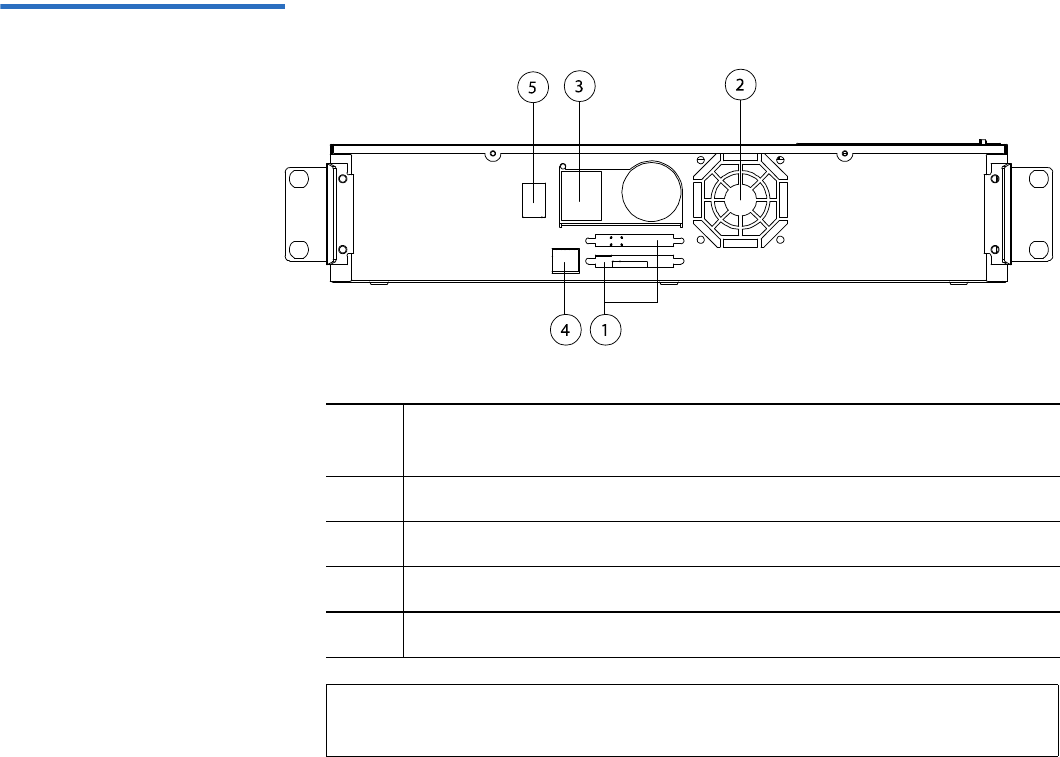
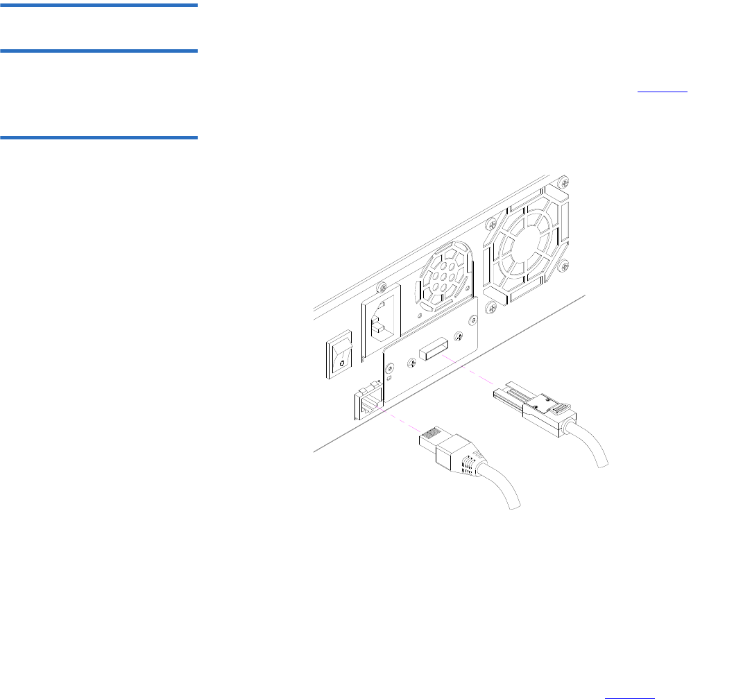
Figure 2 Back Panel Overview
1 68-pin HD SCSI connectors, or a Fibre Channel or SAS
connector
2Fan vent
3 Power connector
4 Remote management Ethernet connector
5Power switch
Note: If the cover must be taken off, there are 26 screws that need to
be removed.
Chapter 2 Installation and Configuration
Connecting Cables
Quantum SuperLoader 3 User’s Guide 18
Connecting Cables
Connecting SCSI and
Power Cables 2To connect the SCSI and power cables to the autoloader, follow these
steps:
1Shut down and turn off the selected server. Turn off all attached
accessory devices, such as printers and other SCSI devices.
2Attach one end of the SCSI cable (included in the accessory kit) to one
of the connectors on the back panel of the autoloader (see figure3).
Figure 3 Cable Connectors
(SCSI Tape Drive)
3Attach the other end of the SCSI cable to the connector on the SCSI
host adapter or to the connector on the previous device on the SCSI
bus.
If the supplied SCSI cable does not fit the connector on your SCSI host
adapter, you either have an incompatible SCSI host adapter or you need
to purchase a cable adapter. Contact your service representative or your
SCSI host adapter manufacturer for information.
SCSI terminator
Ethernet cable
SCSI cable

Chapter 2 Installation and Configuration
Connecting Cables
Quantum SuperLoader 3 User’s Guide 19
4Attach the terminator to the remaining SCSI connector on the back
panel of the autoloader (if the autoloader is the last or only device on
the SCSI bus). Otherwise, attach the cable to the next device on the
SCSI bus. Make sure that the last device on the SCSI bus is properly
terminated.
5Attach one end of your Ethernet cable to the Ethernet port on the
back panel of the autoloader for remote management.
6Attach the other end of the Ethernet cable to your host network port
or router.
7Attach the female connector of the power cable to the power
connector on the back panel of the autoloader (see figure2).
8Plug in the power cable to the nearest properly grounded power
outlet.
9Plug in the host server or workstation and all attached devices.
10 Turn on the autoloader by setting the power switch on the back
panel to the ON position. Turn on any other devices you turned off
earlier. Check the LCD screen to make sure the autoloader is
receiving power. If it is not, check the power connections and your
power source.
During the power on self-test (POST), both LEDs are illuminated
briefly, followed by only the Ready/Activity LED flashing. When the
initialization sequence is complete, the LCD screen displays the Home
screen.
11 Turn on the server.
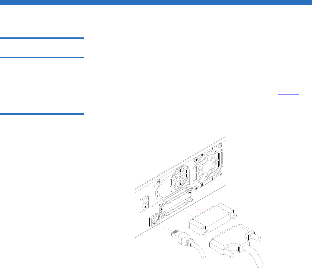
Connecting Fibre
Channel and Power
Cables 2To connect the Fibre Channel and power cables to the autoloader, follow
these steps:
1Attach one end of the Fibre Channel cable (included in the accessory
kit) to the Fibre Channel connector on the back panel of the
autoloader (see figure4).
Chapter 2 Installation and Configuration
Connecting Cables
Quantum SuperLoader 3 User’s Guide 20
Figure 4 Cable Connectors
(Fibre Channel Tape Drive)
2Attach the other end of the Fibre Channel cable to the Fibre Channel
host.
3Attach one end of your Ethernet cable to the Ethernet port on the
back panel of the autoloader for remote management.
4Attach the other end of the Ethernet cable to your host network port
or router.
5Attach the female connector of the power cable to the power
connector on the back panel of the autoloader (see figure2).
6Plug in the power cable to the nearest properly grounded power
outlet.
7Turn on the autoloader by setting the power switch on the back
panel to the ON position. Turn on any other devices you turned off
earlier. Check the LCD screen to make sure the autoloader is
receiving power. If it is not, check the power connections and your
power source.
Fibre Channel cable
Ethernet cable
Chapter 2 Installation and Configuration
Connecting Cables
Quantum SuperLoader 3 User’s Guide 21
During the power on self-test (POST), both LEDs are illuminated
briefly, followed by only the Ready/Activity LED flashing. When the
initialization sequence is complete, the LCD screen displays the Home
screen.
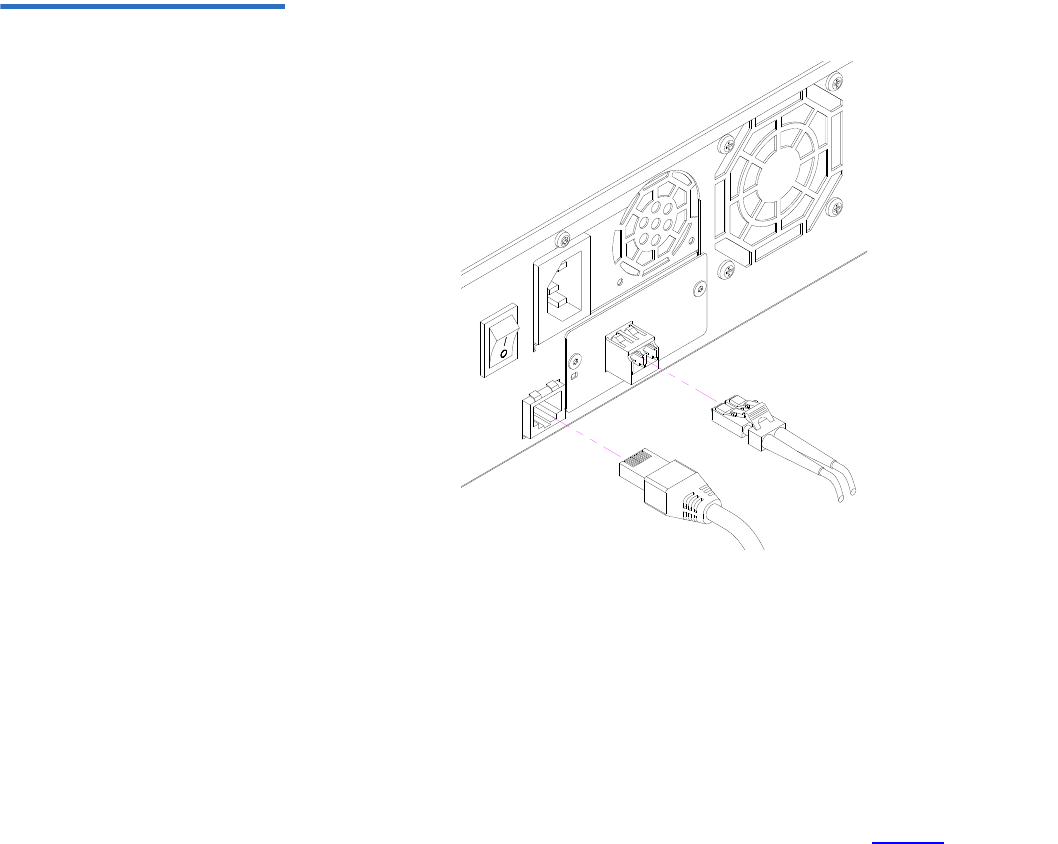
Connecting SAS and
Power Cables 2To connect the SAS and power cables to the autoloader, follow these
steps:
1Attach one end of the SAS cable (included in the accessory kit) to the
SAS connector on the back panel of the autoloader (see figure5).
Figure 5 Cable Connectors
(SAS Tape Drive)
2Attach the other end of the SAS cable to the SAS host.
3Attach one end of your Ethernet cable to the Ethernet port on the
back panel of the autoloader for remote management.
4Attach the other end of the Ethernet cable to your host network port
or router.
5Attach the female connector of the power cable to the power
connector on the back panel of the autoloader (see figure2).
SAS cable
Ethernet cable
Chapter 2 Installation and Configuration
Connecting Cables
Quantum SuperLoader 3 User’s Guide 22
6Plug in the power cable to the nearest properly grounded power
outlet.
7Turn on the autoloader by setting the power switch on the back
panel to the ON position. Turn on any other devices you turned off
earlier. Check the LCD screen to make sure the autoloader is
receiving power. If it is not, check the power connections and your
power source.
During the power on self-test (POST), both LEDs are illuminated
briefly, followed by only the Ready/Activity LED flashing. When the
initialization sequence is complete, the LCD screen displays the Home
screen.

Chapter 2 Installation and Configuration
Preparing the Host and Verifying the Connection
Quantum SuperLoader 3 User’s Guide 23
Preparing the Host and Verifying the Connection
If necessary, install a SCSI, Fibre Channel, or SAS host adapter, software,
and compatible drivers. Refer to the manuals for the host computer and
SCSI, Fibre Channel, or SAS host adapter for detailed instructions. In
addition, follow these general guidelines:
• When the host server is powered on, install software, and/or drivers
that are compatible with the autoloader (see “Windows Operating
System Support” on page 24). Software compatibility information is
available at www.quantum.com. Most backup software packages
require an additional module to communicate with the autoloader
robotics.
• If the host server is connected to a network, check with the system
administrator before turning off power.
• Use proper procedures to prevent electrostatic discharge (ESD). Use
wrist-grounding straps and anti-static mats when handling internal
components.
• Make sure that the host server has an open expansion slot.
• Make sure that your backup application supports the SCSI, Fibre
Channel, or SAS host adapter.
• For the SCSI autoloader interface:
• Depending on the server configuration, you may need to change
the SCSI ID of the autoloader (see “SCSI Autoloader” on
page 70).
• Ensure the autoloader is properly terminated. If the autoloader is
the only SCSI device other than the SCSI host adapter on the
selected SCSI bus, it must be terminated. Likewise, if the
autoloader is physically the last SCSI device on the SCSI bus, it
must be terminated. Only the devices physically at the beginning
and end of the SCSI bus should be terminated. If the host is
located at the beginning of the SCSI bus, the host should already
have a terminator installed.
• Verify the connection between the autoloader and host by going to
Settings>Control Panel>System>Hardware>Device Manager>Tape
Drive and/or Media Changer in Microsoft® Windows® 2000, Microsoft

Chapter 2 Installation and Configuration
Windows Operating System Support
Quantum SuperLoader 3 User’s Guide 24
Windows XP and Windows Server® 2003. For more information on
verifying the connection of SCSI devices, consult the operating
system documentation.
Windows Operating System Support
There are two device drivers associated with the SuperLoader 3
autoloader. One for the autoloader itself, and a second for the tape drive
within the autoloader.
Autoloader Device Driver2• For the SuperLoader 3 autoloader, go to
http://www.quantum.com/ServiceandSupport/
SoftwareandDocumentationDownloads/SuperLoader3/
Index.aspx#Drivers.
Tape Drive Device Driver2• For the LTO-2 drive, go to:
http://www.quantum.com/ServiceandSupport/
SoftwareandDocumentationDownloads/LTO-2Drives/
Index.aspx#Drivers.
• For the LTO-3 drive, go to:
http://www.quantum.com/ServiceandSupport/
SoftwareandDocumentationDownloads/LTO-3Drives/
Index.aspx#Drivers.
Note: Device drivers are required if you intend to use the Microsoft
Windows native backup application. Commercial backup
applications provide all necessary device driver support. Refer
to www.quantum.com for a list of compatible backup
applications.
Please note that Microsoft Windows NT® does not include
native support for autoloaders. A backup application must be
used if using the SuperLoader 3 autoloader under Microsoft
Windows NT.

Chapter 2 Installation and Configuration
Windows Operating System Support
Quantum SuperLoader 3 User’s Guide 25
• For the HP LTO-4 SCSI drive, go to:
Software and Driver Downloads at the HP Web site.
• For the LTO-4 SAS drive, go to:
http://www.quantum.com/ServiceandSupport/
SoftwareandDocumentationDownloads/LTO-4Drives/
Index.aspx#Drivers.
• For the VS160 drive, go to:
http://www.quantum.com/ServiceandSupport/
SoftwareandDocumentationDownloads/DLTVS160/
Index.aspx#Drivers.
• For the DLT-V4 drive, go to:
http://www.quantum.com/ServiceandSupport/
SoftwareandDocumentationDownloads/DLTV4/
Index.aspx#Drivers.
• For the SDLT 600 drive, go to:
http://www.quantum.com/ServiceandSupport/
SoftwareandDocumentationDownloads/SDLT600/
Index.aspx#Drivers.
• For the DLT-S4 drive, go to:
http://www.quantum.com/ServiceandSupport/
SoftwareandDocumentationDownloads/DLTS4/
Index.aspx#Drivers.

Chapter 2 Installation and Configuration
Bar Code Reader
Quantum SuperLoader 3 User’s Guide 26
Bar Code Reader
The bar code reader is enclosed within the body of the autoloader. The
bar code reader automatically scans each cartridge in the magazine upon
power up, after a reset, after an import or export, or when a re-inventory
command is issued (see “Running an Inventory” on page 46). Beyond
that, there is no user interface with the bar code reader via the front panel
operator controls or LCD screen. The information from each label is
stored in memory and available through SCSI and On-board Remote
Management to the computer's operating system or backup application
upon request.
If utilizing the bar code reader, you must apply or slide the bar code
labels into the appropriate slot on the front of each cartridge. The labels
must conform to ANSI/AIM BC1 -1995 Uniform Symbology Specification
Code 39. A set of bar code labels is initially included with the autoloader.
Refer to www.quantum.com for information on obtaining additional bar
code labels.
DLTSage Dashboard
DLTSage Dashboard enables you to more effectively manage and protect
your tape storage environment and is accessible from the Windows Start
menu and device manager. The Tape Security feature included in the
Dashboard gives you the ability to add an electronic key to tape
cartridges. This protects your cartridges from unauthorized access to data
in the event that they are lost or stolen. The Dashboard's Status tab
quickly and easily displays: your drive and media's current health, a dial
that indicates when your drive's next cleaning is due, a graphical display
of your cartridge's available free space, and more.
You can download the latest version of DLTSage Dashboard for the DLT-
V4 and DLT-S4 tape drives from the Quantum Web site at:
www.quantum.com/ServiceandSupport/
SoftwareandDocumentationDownloads/SDLT600/Index.aspx#Drivers

Quantum SuperLoader 3 User’s Guide 27
Chapter 3
3Operating the Autoloader
This chapter covers all aspects of autoloader operation. The following
topics are available:
•Operator's Panel Functionality
•“Using Cartridges” on page 30
•“Using Magazines and Magazine Blanks” on page 35
•“Viewing Status Information” on page 41
•“Running an Inventory” on page 46
•“Data Compression” on page 46
Operator's Panel Functionality
Note: If security is enabled and you try to execute a command
without entering a password, the autoloader displays the
Enter Password screen until you enter a password. Once you
enter a password, the autoloader takes you back to the
command screen that you were at prior to entering the
password.
Chapter 3 Operating the Autoloader
Operator's Panel Functionality
Quantum SuperLoader 3 User’s Guide 28
The front panel consists of two LEDs, four buttons, and a 2-line by 16-
character LCD screen and provides everything you need to monitor
autoloader status and to control all of its functions.
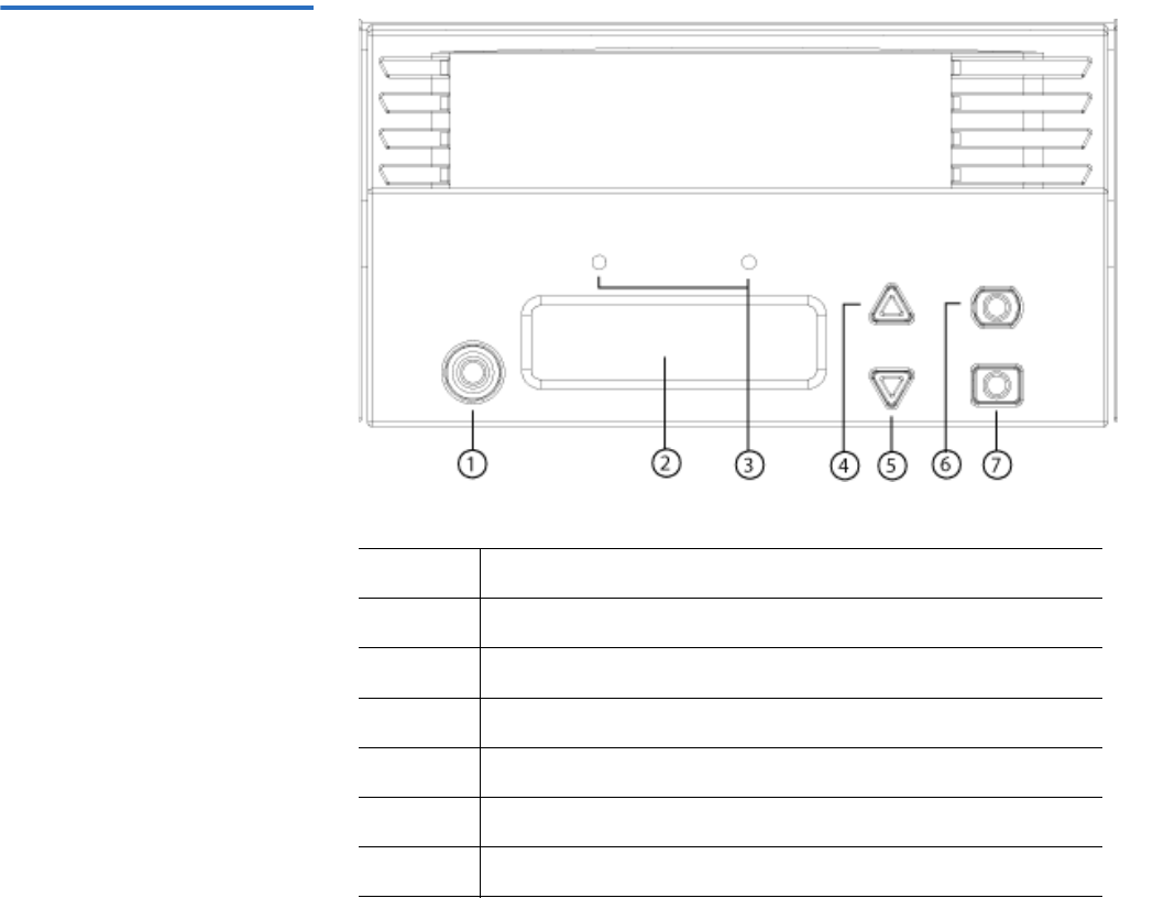
Figure 6 Front Panel
1Power switch
2 Front panel LCD screen
3 Front panel LEDs
4 Scroll up button
5 Scroll down button
6 Escape
7Enter

Chapter 3 Operating the Autoloader
Operator's Panel Functionality
Quantum SuperLoader 3 User’s Guide 29
The functionality of the two front panel LEDs is defined in table 2.
Table 2 Front Panel LEDs
All the functionality accessed from the scrolling menu is password-
protected. Two levels of security are built into the menu. The lower-level
security is the operator level and the higher-level security is the
administrator level. There is one password for each level.
The administrator password allows access to all the functionality
available. The operator password allows access to all the functionality in
the Command and Status submenus.
Enter Passwords 3Many functions on the autoloader may be password-protected to ensure
data integrity. To access the menu items necessary to execute these
functions, you must first enter your password. All passwords are six
numeric digits long.
When you enter a password, all password-protected functionality is
available until you close your browser session. If you do not use the front
panel for a period of time, the main screen displays on the LCD. When
the main screen displays, the autoloader has automatically logged you
out. You will have to re-enter your password again to access the menu
functionality.
Function Green Amber
Power off OFF OFF
Ready ON OFF
Normal activity Flashing OFF
Autoloader attention OFF Flashing
Autoloader error OFF ON

Chapter 3 Operating the Autoloader
Using Cartridges
Quantum SuperLoader 3 User’s Guide 30
Logout 3To log out of the autoloader:
1From the main menu, scroll to Commands, and then press Enter.
2From the Commands submenu, scroll to Log Out, and then press
Enter. Session Complete displays on the LCD.
Using Cartridges
Typically, when you first install the autoloader, you load your cartridges
into the magazines and then load the magazines into the autoloader.
However, you can insert and eject cartridges individually using the
mailslot, or you can eject a magazine, manually load and unload
cartridges, then load the magazine back into the autoloader. The
autoloader automatically detects the presence of a cartridge in the
magazine slot.
If you try to perform an illegal operation, the autoloader refuses to
perform the operation. For example, if you try to load a cartridge through
the mailslot to the drive, but the drive already contains a cartridge, the
mailslot does not unlock. If you try to unload a cartridge from the drive
Note: You can also press Escape to log out. Continue pressing
Escape as required until the main screen displays.
Note: On the front panel menu, whenever you see Enter or Eject, it
means the cartridge enters and leaves the autoloader through
the mailslot. Whenever you see Load or Unload, it means the
cartridge is loaded into or unloaded from the tape drive.

Chapter 3 Operating the Autoloader
Using Cartridges
Quantum SuperLoader 3 User’s Guide 31
while the autoloader is writing to the tape, the command will not be
initiated until the write command is completed.
Inserting a Single
Cartridge 3When you want to load a single cartridge into the autoloader, you can use
the mailslot. However, if the Security option is turned on, you have to
enter a valid password to unlock the mailslot before you can load a
cartridge. When you insert a cartridge through the mailslot, you can load
it into the tape drive or store it in a magazine slot.
To insert a cartridge into the tape drive:
1From the main menu, scroll to Commands, and then press Enter.
2From the Commands submenu, scroll to Enter, and then press Enter.
3From the Enter submenu, scroll to To Drive, and then press Enter. The
message Insert Tape, Push Until Prompted displays on the LCD.
Warning: If a tape cartridge is holding the mailslot door open on
power up, the robot will not move. The system detects
that the mailslot door is open but cannot detect the
presence of the cartridge. If the mailslot door is open, the
bar code scanner laser light may shine out the door and
potentially cause physical injury.
With the mailslot door open, do not insert your hand
through the mailslot door. This is to prevent bodily injury
from the robot. Precautions are in place to prevent the
robotic mechanism functioning in this circumstance.
If the tape cartridge is holding the mailslot door open
during operation, the system keeps track of the tape
movement and continues robotic motion. This can occur if
the robot ejects the cartridge out through the mailslot
door.
Note: After Insert Tape, Push Until Prompted displays on the
LCD, insert the cartridge. After approximately 5 seconds,
the system automatically verifies that a cartridge is
inserted and continues the process. The message Tape
Loaded displays when successfully completed.

Chapter 3 Operating the Autoloader
Using Cartridges
Quantum SuperLoader 3 User’s Guide 32
4Once you have inserted the cartridge, press Enter.
5Press Exit to clear the command and return to the menu.
To insert a cartridge into a magazine slot:
1From the main menu, scroll to Commands, and then press Enter.
2From the Commands submenu, scroll to Enter, and then press Enter.
3From the Enter submenu, scroll to To Location, and then press Enter.
The message Insert Tape, Push Until Prompted displays on the LCD.
4Once you have inserted the cartridge, press Enter.
5Press Exit to clear the command and return to the menu.
Note: For the autoloader, push the cartridge in until it stops. The
cartridge will be about 3 inches (7.5 cm) inside the mailslot.
This may require that you push and have your fingers well
within the mailslot opening. After insertion, the end of the
cartridge will be visible at the back of the mailslot opening.
Note: If the insert cartridge function fails, the cartridge ejects and
you will have to repeat steps 3 and 4 again. The message
Missed Tape displays.
Note: After Insert Tape, Push Until Prompted displays on the
LCD, insert the cartridge. After approximately 5 seconds,
the system automatically verifies that a cartridge is
inserted and continues the process. The message Tape
Loaded displays when successfully completed.
Note: For the autoloader, push the cartridge in until it stops. The
cartridge will be about 3 inches (7.5 cm) inside the
mailslot. This may require that you push and have your
fingers well within the mailslot opening. After insertion,
the end of the cartridge will be visible at the back of the
mailslot opening.
Note: If the insert cartridge function fails, the cartridge ejects
and you will have to repeat steps 3 and 4 again. The
message Missed Tape displays.

Chapter 3 Operating the Autoloader
Using Cartridges
Quantum SuperLoader 3 User’s Guide 33
Moving a Single
Cartridge 3You can easily move a single cartridge from one location to another
inside the autoloader.
1From the main menu, scroll to Commands, and then press Enter.
2From the Commands submenu, scroll to Move, and then press Enter.
The Move screen displays under From:. Scroll to the current location
of the cartridge you want to move. Slots that are occupied by a data
cartridge are indicated by an asterisk (*).
3From To:, scroll to the location to which you want to move the
cartridge. Slots that are occupied by a data cartridge are indicated by
an asterisk (*). Press Enter.
4Press Enter.
If you select an empty location, No Source Element displays on the
LCD. Choose a different location.
If you select a location that is already occupied, Destination Full
displays on the LCD. Choose a different location.
Ejecting a Single
Cartridge 3When you want to remove a single cartridge from the autoloader, you
can specify the cartridge you want by bar code or location, or choose the
cartridge currently in the tape drive.
To eject a cartridge by bar code (if you have a bar code reader):
1From the main menu, scroll to Commands, and then press Enter.
2From the Commands submenu, scroll to Eject, and then press Enter.
3From the Eject submenu, scroll to Tape, scroll to Mailslot, and then
press Enter.
4Scroll to By Barcode.
A bar code label displays.
5Scroll to the label that corresponds to the cartridge you want to eject.
Press Enter.
To eject a cartridge by location:
1From the main menu, scroll to Commands, and then press Enter.
2From the Commands submenu, scroll to Eject, and then press Enter.
Chapter 3 Operating the Autoloader
Using Cartridges
Quantum SuperLoader 3 User’s Guide 34
3From the Eject submenu, scroll to Tape, scroll to Mailslot, and then
press Enter.
4Scroll to By Location.
Slots that are occupied by a data cartridge are indicated by an asterisk
(*). The slot that is occupied by a cleaning tape is indicated with an at
sign (@) if Auto Clean is enabled. Scroll to the slot containing the
cartridge you want to eject.
5Press Enter.
The cartridge you want is ejected from the mailslot.
To eject a cartridge from the tape drive:
1From the main menu, scroll to Commands, and then press Enter.
2From the Commands submenu, scroll to Eject, and then press Enter.
3From the Eject submenu, scroll to Cartridge, and then press Enter.
4Scroll to From Drive, and then press Enter.
The cartridge you want is ejected from the mailslot.
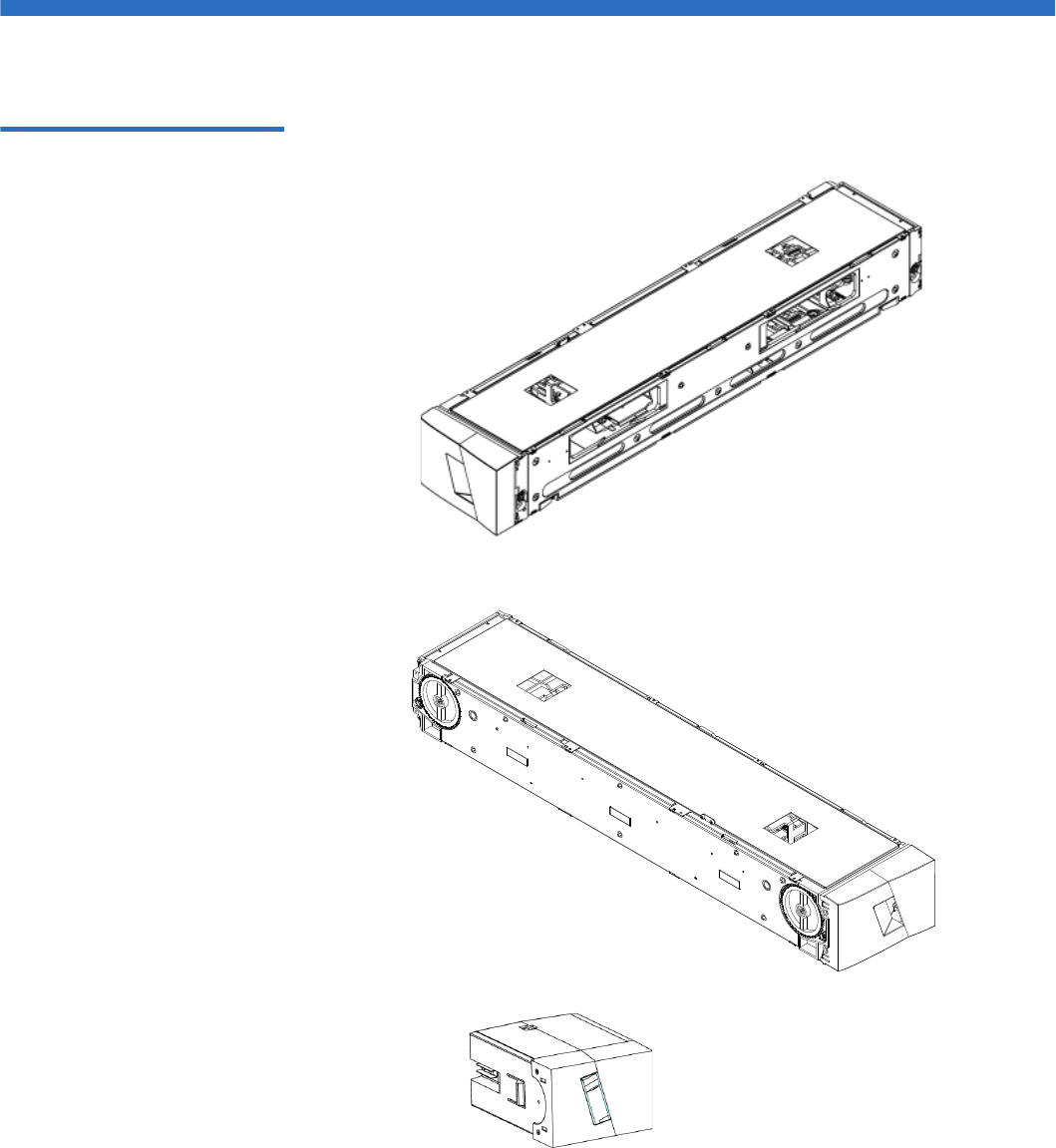
Chapter 3 Operating the Autoloader
Using Magazines and Magazine Blanks
Quantum SuperLoader 3 User’s Guide 35
Using Magazines and Magazine Blanks
Figure 7 Left Magazine
Inside edge view
of left magazine
Outside edge view
of left magazine
Left magazine blank

Chapter 3 Operating the Autoloader
Using Magazines and Magazine Blanks
Quantum SuperLoader 3 User’s Guide 36
The autoloader will not run unless both magazine openings are properly
closed. One way that you can close the openings is to use two magazines.
If you use only one magazine, then you must fill the other magazine
opening with a magazine blank for the unit to become operational.
Ejecting a Magazine 3When you want to remove several cartridges at once, eject the
magazine(s) first.
To eject a magazine:
1From the main menu, scroll to Commands, and then press Enter.
2From the Commands submenu, scroll to Eject, and then press Enter.
3On the Eject submenu, scroll to Right Magazine or Left Magazine, and
then press Enter.
You will hear a distinctive popping sound as the appropriate
magazine is ejected from the autoloader. Left magazine has been
ejected or Right magazine has been ejected displays on the LCD.
4Grasp the magazine by the handle with one hand and slide it out,
supporting it underneath with the other hand.
Note: Magazines, magazine blanks, and magazine handles are not
interchangeable between drive types. Please order the
appropriate part numbers when replacing these items.
Note: To prevent damage to the autoloader or the magazine, use
both hands when removing the magazine from the
autoloader supporting the entire length of the magazine.
Note: Once you eject a magazine, you must fully remove it or
fully reinstall it before powering off the autoloader. Before
returning a magazine to the autoloader, manually turn the
wheels on the side of the magazine. If they move freely,
the cartridges are properly seated. If the wheels do not
turn freely, check the cartridges and remove and replace as
needed.

Chapter 3 Operating the Autoloader
Using Magazines and Magazine Blanks
Quantum SuperLoader 3 User’s Guide 37
Magazine Load/Unload
Command 3When issuing a Load/Unload command to the autoloader, the system
automatically ejects the right-hand magazine. To remove the left-hand
magazine using the Load/Unload command, you must:
1Remove the right magazine.
2Replace the right magazine with a magazine blank.
3Issue the Load/Unload command again. The system will then eject
the left magazine.
4If you want to have the magazine in the right-hand bay, replace the
magazine blank in the right-hand bay with a cartridge magazine.
Installing a Magazine 3To install a magazine into the autoloader:
1Grasp the magazine by the handle with one hand and support it
underneath with the other hand.
2Slide the magazine into the magazine bay until it clicks.
Make sure that you position the magazine correctly. It should slide
into the magazine bay smoothly. If you meet resistance, verify the
orientation of the magazine.
The magazine is correctly installed when you feel it click into place
and the front is flush with the front panel. Left Mag Inserted or Right
Mag Inserted displays on the LCD. The autoloader automatically
proceeds to run an inventory.
Caution: Be careful not to turn the knob on the side of the
magazine while the magazine is partially inserted into
the autoloader. Doing so may cause damage to the
magazine or the autoloader.
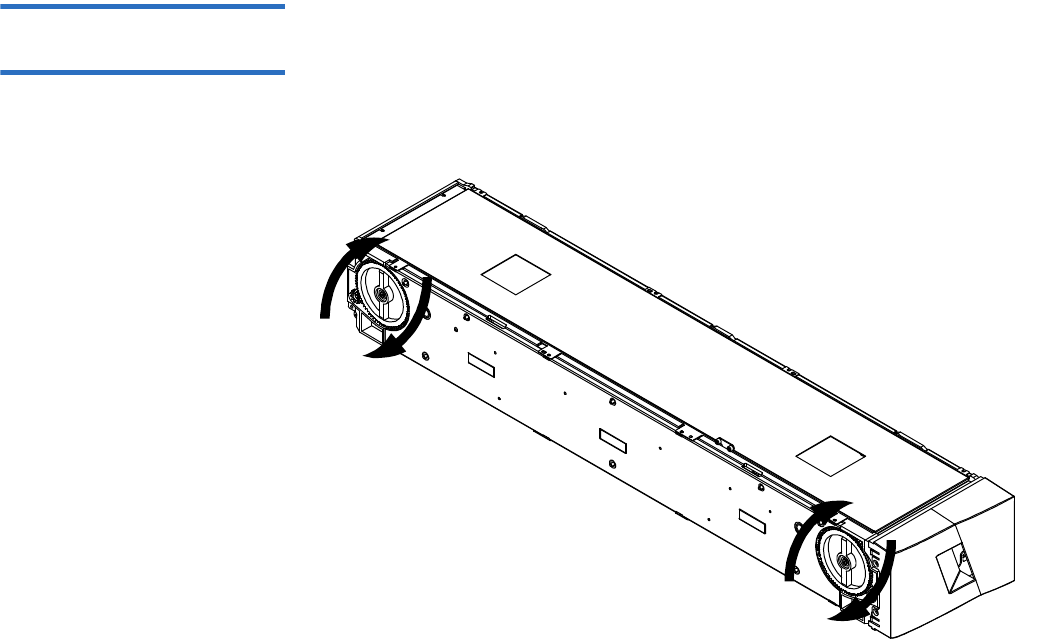
Chapter 3 Operating the Autoloader
Using Magazines and Magazine Blanks
Quantum SuperLoader 3 User’s Guide 38
Manually Operating the
Magazine 3The following section describes how to operate a magazine.
There are two knobs located on each end of the magazine. You can move
the slots within the magazine by turning these two knobs and aligning a
slot with one of the two openings.
6/14
3/11
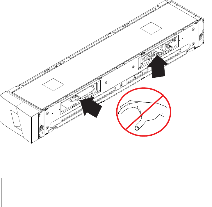
Chapter 3 Operating the Autoloader
Using Magazines and Magazine Blanks
Quantum SuperLoader 3 User’s Guide 39
Do not rotate the magazine by inserting your hand and pushing the
cartridge carriers. You can use the openings in the magazine to load and
unload cartridges from the eight slots within each magazine.
Note: It is recommended that you fully remove the magazine to
load and unload cartridges. If the magazine is not fully
removed, do not rotate the magazine.
6/14
3/11

Chapter 3 Operating the Autoloader
Using Magazines and Magazine Blanks
Quantum SuperLoader 3 User’s Guide 40
To Identify a Slot: 3
Each slot has an identification number that is exposed when the slots are
in the upper section of the magazine. With the magazine removed from
the autoloader, you can see the identification mark on the top side of the
magazine through one of two windows on the upper surface of the
magazine.
Each magazine carrier is labeled 1/9, 2/10, 3/11, and so forth. Lower
numbers 1 - 8 reference slots in the left magazine. Higher numbers 9 - 16
reference slots on the right magazine if the optional right magazine is
installed.
To Load Cartridges into a Fully Ejected Magazine: 3
1To load cartridges into the magazine, center a slot within one of the
openings located on the side of the magazine.
2Properly orient the cartridge.
3Fully insert the cartridge into the slot.
When pushing the cartridge into the slot, you will feel a small
resistance (detente) until the cartridge is properly latched into the
slot. All forward progress stops when the cartridge is fully inserted.
You can remove a cartridge in the same manner as you insert it. Use the
knobs to center the desired slot(s) in the openings on the side of the
magazine. Using your thumb and index finger, pull out the cartridge.
You will feel a small resistance, but continue to pull the cartridge until it
comes free.
To Unload Cartridges from a Fully Ejected Magazine: 3
1Pull the ejected magazine until the large upper slot is accessible.
2Rotate the desired slot into position (centered in the opening). Either
load or unload a cartridge to that location. Do not expose more than
the large upper opening when manually operating the magazine.
Note: There is a keying feature in each slot that only allows you
to fully insert the cartridge one way.

Chapter 3 Operating the Autoloader
Viewing Status Information
Quantum SuperLoader 3 User’s Guide 41
Viewing Status Information
From the scrolling menu on the LCD, you can view the autoloader status,
firmware version, element status, tape drive status, tape drive version,
and Ethernet information.
Viewing SuperLoader 3
Autoloader Status 3The autoloader status provides information about:
• Whether a magazine is installed or not
• SCSI, SAS, or Fibre Channel connection status
• Ethernet connection status
• Whether a bar code reader is installed or not
To view the autoloader status:
1From the main menu, scroll to Status, and then press Enter.
2From the Status submenu, scroll to Autoloader, and then press Enter.
3From the Autoloader submenu, scroll to Status, and then press Enter.
A list of messages similar to the following displays:

Chapter 3 Operating the Autoloader
Viewing Status Information
Quantum SuperLoader 3 User’s Guide 42
Table 3 Autoloader Status
Viewing Firmware
Version 3To view the current firmware version, use the following procedure:
1From the main menu, scroll to Status, and then press Enter.
2From the Status submenu, scroll to Autoloader, and then press Enter.
3From the Autoloader submenu, scroll to Version, and then press Enter.
A list of messages displays on the LCD. The firmware version is
listed as Firmware: VX.XX where X.XX is the current installed version
of the firmware.
Status Message Description
Magazines L=* The left magazine is present.
R=* The right magazine is present.
SCSI ID A digit 0 through 7
(default 5)
The assigned SCSI ID for the autoloader.
SAS SAS Interface SAS connection.
Topology
(Fibre Channel)
Auto Negotiate,
Loop, or P2P
The configured Fibre Channel connection.
Speed
(Fibre Channel)
Auto Negotiate,
1 Gig, or 2 Gig
The configured Fibre Channel speed.
Loop ID
(Fibre Channel)
0 – 127 Valid only with Topology set to Loop.
Mode Random The change mode is set to Random.
SEQUENTIAL The change mode is set to Sequential.
BC Reader Yes or No A bar code reader is present.

Chapter 3 Operating the Autoloader
Viewing Status Information
Quantum SuperLoader 3 User’s Guide 43
Table 4 Firmware Version
Fields
Viewing Element Status 3The element status reports the status of the magazine slots. The status
indicates whether a slot contains a cartridge or not, and which slot is
allocated as the cleaning cartridge's slot. To view an element's status:
1From the main menu, scroll to Status, and then press Enter.
2From the Status submenu, scroll to Autoloader, and then press Enter.
3From the Autoloader submenu, scroll to Element Status, and then
press Enter.
4Press Enter.
You can scroll through each of the slots. Slots that are occupied by a
data cartridge are indicated by an asterisk (*). The empty slot that is
assigned to a cleaning cartridge is indicated with an exclamation
point (!). The slot that is occupied by a cleaning cartridge is indicated
with an at sign (@).
5Scroll to the slot containing the cartridge for which you want to see
the label, or the cartridge you want to move, and then press Enter.
The Element Status screen displays the bar code label for that
cartridge. A move command also displays on the screen.
Field Description
Firmware The number indicates the firmware version.
EDC The number indicates the Error Correction Code that
was generated when the firmware was installed. The
autoloader uses this number to verify that the
firmware and the memory holding the firmware are
good.
HW Rev The number indicates the hardware version.
ME Rev The number indicates the mechanical version.
Note: The Move command displays only if the security is
disabled or if you are logged in as Administrator or
Operator.

Chapter 3 Operating the Autoloader
Viewing Status Information
Quantum SuperLoader 3 User’s Guide 44
If you want to move the cartridge, scroll until the location you want
to move to displays under To:, and then press Enter. If you do not
want to move the cartridge, press Escape.
Viewing Tape Drive
Status 3To view the tape drive status:
1From the main menu, scroll to Status, and then press Enter.
2From the Status submenu, scroll to Drive, and then press Enter.
3From the Drive submenu, scroll to Status, and then press Enter.
A list of messages displays. These messages may include:
Table 5 Drive Status Fields
Viewing Tape Drive
Version 3To view the tape drive version:
1From the main menu, scroll to Status, and then press Enter.
2From the Status submenu, scroll to Drive, and then press Enter.
3From the Drive submenu, scroll to Version, and then press Enter.
A list of messages displays. These messages may include:
Field Description
SCSI ID or
Fibre Channel
Indicates the drive’s SCSI ID number or a Fibre
Channel drive.
SAS Interface Indicates a SAS drive.
Loader LUN Indicates the Logical Unit Number (LUN) of the
media changer device.
Compression Indicates whether the tape drive compression is
enabled or disabled.
Drive Tape Indicates whether the tape drive is present or not.

Chapter 3 Operating the Autoloader
Viewing Status Information
Quantum SuperLoader 3 User’s Guide 45
Table 6 Drive Version Fields
Viewing Ethernet
Information 3To view the Ethernet information:
1From the main menu, scroll to Status, and then press Enter.
2From the Status submenu, scroll to Ethernet, and then press Enter.
A list of messages displays. These messages may include:
Table 7 Ethernet Information
Fields
Field Description
Product Type Indicates the type of drive installed.
Version Indicates the version number of the drive.
Field Description
MAC Address Indicates the unique network identifier associated
with the autoloader.
IP Address Indicates the static IP address or currently assigned
dynamic IP address. The text DHCP displays in this
case.
Network Indicates whether the autoloader is connected to the
network or not and at what speed.

Chapter 3 Operating the Autoloader
Running an Inventory
Quantum SuperLoader 3 User’s Guide 46
Running an Inventory
The autoloader automatically runs an inventory whenever you power it
back on or insert a magazine. An inventory checks each magazine slot,
the drive, the picker, and the mailslot to determine if a cartridge is
present. If so, it also reads the bar code label, if available. If you need to
run an inventory in addition to this, you can do so manually.
To perform an inventory manually:
1From the main menu, scroll to Commands, and then press Enter.
2From the Commands submenu, scroll to Inventory, and then press
Enter. The autoloader scans the bar codes of all the cartridges present.
Data Compression
Compressing the data means that the autoloader can write more data to
the same amount of tape. Compression also increases the performance of
the data transfers from or to the SCSI bus. The data compression is drive
dependent and cannot be set from the front panel or On-board Remote
Management. Your backup application package may also have
information on compression. The front panel display will indicate
whether data compression is Enabled or Disabled.
Note: No bar code labels can be read if there is a tape in the picker.

Quantum SuperLoader 3 User’s Guide 47
Chapter 4
4On-board Remote Management
This chapter covers the operation, configuration, and troubleshooting of
the autoloader Remote Management Unit (RMU). The following topics
are available:
•On-board Remote Management Overview
•“Configurations Page” on page 50
•“Updates Page” on page 61
•“Diagnostics Page” on page 62
•“Commands Page” on page 64
On-board Remote Management Overview
Your Quantum SuperLoader 3 autoloader firmware includes an Ethernet
interface to allow remote administration of the autoloader. The interface,
called the On-board Remote Management, includes a Web server that
provides a Hypertext Markup Language (HTML)-based graphic user
interface (GUI) for ease of use.
Many of the operations that you perform from the front panel, you can
also perform remotely using On-board Remote Management. These
functions include moving tapes, sequential operations, system operations

Chapter 4 On-board Remote Management
On-board Remote Management Overview
Quantum SuperLoader 3 User’s Guide 48
options, networking options, security options, running diagnostic tests,
and performing system updates.
Opening On-board
Remote Management 4On-board Remote Management has an HTML interface, which means
you use a browser to open it. The following Web browsers are supported:
• For Microsoft Windows—Microsoft Internet Explorer 5.5 or later
• For Microsoft Windows Server 2003—Microsoft Internet Explorer 6.0
or later (with latest security patches)
•For Redhat
® 2.1—Mozilla™ 1.4.2
• Firefox™ 1.0
You need an operator password to access the Commands page, and you
need an administrator password to access the Configurations, Diagnostics,
and Updates pages.
To open On-board Remote Management:
1From your computer, open your Web browser.
2In the browser's address field, enter the IP address for your
autoloader (see “Viewing Ethernet Information” on page 45).
Note: Only use the Diagnostic command when the autoloader is
known to be idle and unavailable to host backup/restore
applications. Use of the Diagnostic commands from On-board
Remote Management should not be issued while the
autoloader is being used by host applications. The autoloader
will recognize when the drive or autoloader is executing host
commands and will respond appropriately to prevent
application failures. A Diagnostic command being issued
between host application commands may not be recognized
resulting in a failed application, such as a failed backup/
restore job.
Note: To log out of the system, you must close your browser to end
the session.

Chapter 4 On-board Remote Management
On-board Remote Management Overview
Quantum SuperLoader 3 User’s Guide 49
The Home page displays in your browser window.
Viewing Status
Information 4Status information displays on the right-hand side of the Home page and
every page of On-board Remote Management except for the Updates
page. The status information is updated every 10 seconds. Changes to the
status appear in the status window update, but may take approximately
60 seconds to refresh. You can also click Refresh Status to get an
immediate update of the system.
The menu headings also appear at the top of every page. To access the
functionality under the menu heading, click the specific menu heading.
The first time that you connect, On-board Remote Management prompts
you for your username and password, then displays the opening page for
that menu.
Default Username and
Password 4The default username for On-board Remote Management is guest. The
default password is guest.
The username and password are case sensitive and should be entered in
all lower case letters. The default username and password are valid if no
usernames have been configured.
Time Display 4The time displayed is either regular time or power-on time. Regular time
is Month/Date/Year time, such as Nov/21/2004 19:28. Power-on time is
Power On Cycles (POC)/Power On Hours (POH), such as POC:00121,
POH:00002:07:45.
• POC (5-digit number) is the number of times the system has booted
since it was manufactured.
• POH is the number of hours, minutes, and seconds that the system
has been on since the current boot occurred.
Note: When using the On-board Remote Management page with
Microsoft Internet Explorer, be sure to enable the Allow
META REFRESH option.
On Internet Explorer version 6.0, this feature is controlled
through the Tools>Internet Options menu selection under
the Security tab.

Chapter 4 On-board Remote Management
Configurations Page
Quantum SuperLoader 3 User’s Guide 50
Feedback on Pages 4If there is feedback from the system when you submit a request, the
feedback displays beneath the submit button. In some cases, you may
have to scroll to see the feedback information.
Configurations Page
The Configurations page includes a submenu on the left-hand side of the
page. You can set the System Operations, Networking, and Security
options from this page.
System Operations
Options 4The options listed under System Operations include SCSI ID (or Fibre
Channel), SAS, Mode, Compression, Cleaning Tape, Magazines, and System
Time.
SCSI ID 4
You can change the drive's SCSI ID from On-board Remote Management.
To change the SCSI ID:
1From any page, click the Configurations heading. The Configurations
screen displays.
2Under System Operations, select SCSI ID.
3Click the drop-down box to select a number to assign for the new
SCSI ID.
4Click submit.
Note: You must perform a system reset before the new SCSI ID
takes effect, or you can use the front panel to power cycle
your machine.

Chapter 4 On-board Remote Management
Configurations Page
Quantum SuperLoader 3 User’s Guide 51
Fibre Channel 4
You can select the Fibre Channel parameters from On-board Remote
Management.
To select the Fibre Channel parameters:
1From any page, click the Configurations heading. The Configurations
screen displays.
2Under System Operations, select Fibre Channel.
3Under Fibre Channel, select the desired Topology.
•Auto Negotiate
• Peer to Peer
• Loop
• Loop ID
4Under Fibre Channel, select the desired Speed.
•Auto Negotiate
•1 Gig
•2 Gig
5Click submit.
Note: In a native Fibre Channel device, dynamic World Wide
Naming is supported.
Note: You must perform a system reset before the changes take
effect, or you can use the front panel to power cycle your
machine.

Chapter 4 On-board Remote Management
Configurations Page
Quantum SuperLoader 3 User’s Guide 52
SAS 4
You can select SAS parameters to enable or disable transport layer retries.
To set the SAS parameters:
1From any page, click the Configurations heading. The Configurations
screen displays.
2In the SAS section of the page, the current selection is marked. To
change the selection, select the other option. Click submit.
Mode 4
You can set the autoloader to either Random or Sequential. The default
change mode is Random.
In Random mode, you (or the backup software) can specify which
cartridge you want to use and where you want it to go. You will probably
use this mode the most.
The Sequential mode supports certain backup applications that do not
manage media. During backup, when one cartridge is read or written to
the end of the tape, the autoloader automatically returns that cartridge to
its slot and loads the cartridge from the next higher numbered slot to the
tape drive to be read or written to. This continues until the backup
software stops accessing the drive or until all the cartridges have been
sequentially accessed. The autoloader does not move the media until the
host requests the tape drive to unload the tape via a SCSI unload
command.
In Sequential Cycle mode, which is an option of the Sequential mode, the
autoloader automatically starts over with magazine slot 1 when the last
cartridge is used (slot 16 or highest filled slot). If this change mode is not
Note: You must perform a system reset before the new mode
takes effect, or you can use the front panel to power cycle
your machine.
Note: In Sequential mode, the medium changer does not appear in
the Device Manager. The medium changer will reappear in
Device Manager if you return the system to Random mode. This
is to allow for operating systems that do not support multiple
LUNs.

Chapter 4 On-board Remote Management
Configurations Page
Quantum SuperLoader 3 User’s Guide 53
set, the autoloader stops when the last cartridge available has been used.
In Sequential Cycle mode, the autoloader continues to cycle until a user
stops it.
To set the Mode:
1From any page, click the Configurations heading. The Configurations
screen displays.
2In the Mode section of the page, the current mode is marked. To
change the mode, select a different option. The Sequential Cycle check
box is ignored if Sequential mode is not selected.
3Click submit.
Compression 4
For the Quantum SuperLoader 3 autoloader, data compression is drive-
dependent. The front panel and On-board Remote Management will
display whether or not compression is enabled.
Compressing the data means that the drive can write more data to the
same amount of tape. Compression also increases the performance of the
data transfers from or to the SCSI bus.
To view the compression setting:
From any page, click the Configurations heading. The Configurations
screen displays. Under the Compression heading, the current
compression setting is displayed as Compression Enabled or Compression
Disabled.
Cleaning Tape 4
To enable or disable the Auto Clean function, you must also designate a
full slot for the cleaning tape cartridge. If a slot has not been designated,
the box displays None. To designate the cleaning tape slot:
Note: You must perform a system reset before the new mode
takes effect, or you can use the front panel to power cycle
your machine.
Note: Compression cannot be changed from the front panel or On-
board Remote Management of the autoloader.

Chapter 4 On-board Remote Management
Configurations Page
Quantum SuperLoader 3 User’s Guide 54
1Load a cleaning tape into an empty slot using the Commands page.
2Enable or disable Auto Clean by selecting the check box.
To set Auto Clean:
1From any page, click the Configurations heading. The Configurations
screen displays.
2Scroll to Cleaning Tape.
If a check mark displays in the box next to Auto Clean, the option is
enabled. To disable Auto Clean, click the box to remove the check
mark. If no check mark displays in the box next to Auto Clean, the
option is disabled. To enable Auto Clean, click the box to enter a check
mark.
3In the Cleaning Tape Location field, select the appropriate slot location
where you installed the cleaning tape. If Auto Clean is disabled,
cleaning is managed by the backup package you have installed
instead.
4Click submit.
Setting the Magazines 4
This setting is used to report the number of storage elements and the
element address to the SCSI host. This setting must match the physical
configuration in order for correct information to be reported. This setting
only affects the information reported to the SCSI host. This setting does
not affect the access to magazine slots from the front panel or On-board
Remote Management. Those interfaces are based on the physical
configuration.
When configured for Both magazines, the autoloader always reports 16
storage elements to the SCSI host. This allows the removal and
reinstallation of magazines without affecting what is reported to the host.
When configured for Left or Right, the autoloader will always report eight
storage elements to the SCSI host.
Note: If Auto Clean is disabled, the cleaning tape will
automatically be ejected via the mailslot. Cleaning is
managed by the backup package you have installed
instead.

Chapter 4 On-board Remote Management
Configurations Page
Quantum SuperLoader 3 User’s Guide 55
The element addresses vary depending on which magazine is configured.
If Left or Right is selected, and both magazines are physically installed,
the front panel and On-board Remote Management allow the user access
to the other magazine, but the SCSI host will not have access.
To set the Magazines option:
1From any page, click the Configurations heading. The Configurations
screen displays.
2Scroll to Magazines. The Magazines options display.
A check mark displays after the currently enabled mode.
3Do one of the following:
• To leave the Magazines mode unchanged, press Esc.
•To change the Magazines configuration, scroll to the setting you
want for the autoloader, selecting the appropriate check box, and
then click submit. These settings include Both, Right, and Left.
The message This will require a power cycle and ISV configuration
change. Enter To Continue is displayed.
• To continue with the change, press submit. The message Please
power cycle the tape autoloader and reconfigure the ISV app.
displays.
Setting the System Time 4
The system time is displayed by On-board Remote Management and is
used internally for logging events and errors.
The time will be reset automatically if a time server is configured.
Otherwise, the time must be set through On-board Remote Management.
The time zone setting is not lost when powered off.
Note: If the time was set using On-board Remote Management,
whether connected to a time server or not, the autoloader
automatically corrects for daylight savings time. If the time
does not properly correct for daylight savings time, you must
correct for daylight savings time manually.

Chapter 4 On-board Remote Management
Configurations Page
Quantum SuperLoader 3 User’s Guide 56
To set the system time:
1Using the first drop-down list next to Time Zone, select the number of
hours difference between your local time and Greenwich Mean Time
(GMT).
2Below the Time Zone field, select the current Month drop-down list.
3In the Day field, type the current day of the month.
4In the Year field, type the current year.
5In the Hour text box, type the current hour in 24-hour format.
6In the Minute text box, type the current minute.
7Click submit to save the information.
Setting Network Options 4
When you originally installed the autoloader, you set the Ethernet
configurations through the front LCD panel. However, you can modify
them through On-board Remote Management. The options include
Current Network Parameters, Set IP, and Set Network Configuration. To
change the Ethernet configurations:
To view the Current Network Parameters:
1From any page, click the Configurations heading. The Configurations
screen displays.
2From the Configurations menu, click Networking.
The Current Network Parameters area displays the current IP address,
MAC address, and the speed setting for the Ethernet connection.
In the Set IP section, if a check mark displays in the box next to DHCP, the
dynamic IP address option is enabled. This means that with every reset of
the system, the IP address may change depending on the network
administrator's settings.
To Set IP address:
1Clear the check box to remove the check mark from the DHCP field, if
applicable.
Note: For example, if you live in Colorado, the time difference is
–6 hours in the summer and –7 hours in the winter.

Chapter 4 On-board Remote Management
Configurations Page
Quantum SuperLoader 3 User’s Guide 57
2In the IP address fields, type the static IP address using the <Tab> key
to move from box to box.
3If no check mark displays in the box next to DHCP, the static IP
address option is enabled. To change a static IP address, type in the
new address in the IP address fields using the <Tab> key to move
from box to box.
4To change the IP address from a static address to a dynamic address,
click the box next to DHCP.
To Set Network Configuration:
1To change the values of the subnet mask, gateway, Simple Network
Management Protocol (SNMP) server, or the time server, type in the
new address, using the <Tab> key to move from box to box.
2Click submit.
Setting Security Options 4
When you enable the security option, users must enter a password to
access the autoloader's front panel functionality. A password allows
either administrator-level access or operator-level access (see “Setting
Security” on page 78). To set security:
1From any page, click the Configurations heading. The Configurations
screen displays.
2On the left-hand side of the screen, click Security. The System
Security section of the screen displays.
3To enable front panel security, select the check box next to Front Panel
Security Enabled.
4If the check box is blank, the security option for the front LCD panel
is not enabled.
5Click submit.
To reset the front panel password:
1From any page, click the Configurations heading. The Configurations
screen displays.
2On the left-hand side of the screen, click Security.
3Select the check box next to Reset Front Panel Password. A check
mark displays.

Chapter 4 On-board Remote Management
Configurations Page
Quantum SuperLoader 3 User’s Guide 58
4Click submit.
To set User Administration:
1From any page, click the Configurations heading. The Configurations
screen displays.
2On the left-hand side of the screen, click Security.
3From the drop-down list next to Select User Type, select Operator 1,
Operator 2, Administrator 1 or Administrator 2.
4In the Username field, enter a user name.
5In the Password field, enter the new password.
6In the Verify Password field, re-enter the same new password.
7Click submit.
To set the Client Authorization Control:
1From any page, click the Configurations heading. The Configurations
screen displays.
2On the left-hand side of the screen, click Security.
Scroll to Client Authorization Control. In this section is a list of the IP
addresses that are authorized to perform functions using On-board
Remote Management for this specific unit. There are two sets of IP
address boxes. You can individually enable/disable and configure
each set.
• If enabled, each set can be used to specify either a range of IP
addresses or a pair of specific IP addresses that are allowed to
administer this unit. A set can also be used to specify a single IP
address if the desired IP address is entered into both the “a” and
“b” portions of the set. When a set is used to specify a range of IP
addresses, the “b” portion of each address set must be greater
than or equal to the “a” portion of that address set.
Note: To view the list of currently defined users, click submit
with Select User Type.
Note: To delete a user, Select User Type and click submit with the
User Name and Password fields blank.
Chapter 4 On-board Remote Management
Configurations Page
Quantum SuperLoader 3 User’s Guide 59
• If neither set is enabled, any IP client can administer the unit. If a
single set is enabled, only clients that pass the test specified by
that set are allowed administrator access. If both sets are enabled,
any client that passes either of the two filter tests can administer
the unit.
The Web server always allows any client to view the status
information of the unit, regardless of the authorized client list or the
overlap control policy.
3Use the drop-down box to select Enable or Disabled.
4Type the IP addresses in the appropriate boxes.
5Click submit to save.
Client Overlap Control is a management policy on controlling how the
Web server handles overlapping control requests from multiple clients on
the authorized client list. The options include No Locking, Full Locking,
and Time-Based Locking.
•No Locking allows multiple clients to have unrestricted access to
control the system as long as they are on the authorized client list.
•Full Locking permits only one authorized client to issue control
requests at a time. This client must release the lock by clicking the
Home option in the upper frame of the page to permit other
authorized clients to have control access.
•Time-Based Locking is similar to Full Locking in that only one
authorized client can have control access at once, but the lock is
automatically released after the specified number of seconds of
inactivity have elapsed.
After selecting the appropriate policy by clicking the check box, click
submit to save the changes.
1From any page, click the Configurations heading. The Configurations
screen displays.
2On the left-hand side of the screen, click Security.
3Select a security option from the Client Overlap Control options:
•No locking allows multiple users to access the system and issue
requests.
•Full Locking allows only one user to access the system and issue
requests.

Chapter 4 On-board Remote Management
Configurations Page
Quantum SuperLoader 3 User’s Guide 60
•Time-based Locking allows only one user to access the system and
issue requests with the lock expiring after a designated amount
of inactivity (in seconds).
•Home is used to release a full or time-based lock and permit
another user to access the system.
4Click submit.
Note: Locking is only available to users on the authorized client
list.
Note: To log out of the system, you must close your browser to
end the session.
Note: By entering an improper range of IP addresses, a user
could possibly lock out all IP clients from administering
the autoloader. If this occurs, you can restore the default
values by running Restore Default from the front panel
Configuration Menu.

Chapter 4 On-board Remote Management
Updates Page
Quantum SuperLoader 3 User’s Guide 61
Updates Page
You can browse to find system updates and then upload the updates. To
get system updates:
1From any page, click the Updates heading. The Firmware Update
screen displays.
2Click Browse to navigate to the host system for the update file. The
file should end in an .img extension.
3Click Upload.
4Click OK in response to the confirmation box. The autoloader
automatically uploads the new code and processes it to the system.
Note: A Microsoft issue can keep a user from updating drive or
loader firmware over the On-board Remote Management
interface. This can occur under Windows Server 2003 with
Service Pack 1 (SP1), or if a user has installed Microsoft
Security Update MS05-019. This problem will appear with
a 6F Communication Error message on the front panel
with the warning light on. On-board Remote Management
will continue to report the autoloader status as
Initialization.
Microsoft has described a workaround for this problem in
their product with Technical Support Article 898060 (http://
support.microsoft.com/default.aspx?scid=898060). If this
problem occurs, the autoloader should be restarted to
avoid further communication errors.

Chapter 4 On-board Remote Management
Diagnostics Page
Quantum SuperLoader 3 User’s Guide 62
Diagnostics Page
From the Diagnostics page, you can run various tests on the autoloader.
You can also view error and history logs, test progress, identify the
physical unit in a rack, or reset the system.
Running Diagnostic
Tests 4You can perform the following diagnostic tests from On-board Remote
Management:
•Loader—Picker Test
• Loader—Magazine Test
• Loader—Inventory Test
• Random Moves
Viewing Error or History
Logs 4To view error or history logs:
1From any page, click the Diagnostics heading. The Diagnostics screen
displays.
2Under View Error and History Logs, click View Logs. You can also save
the logs to a file by clicking Save Logs. If you save the logs to a file,
you must select a destination folder within 60 seconds.
Note: On-board Remote Management allows you to request all
diagnostic tests, but any tests that require a cartridge to be
inserted will time out unless someone manually inserts the
cartridge at the appropriate time.
Note: View Logs allows you to view a summary of the hardware,
software and update logs for the autoloader.
Save Logs saves detailed log information to a file for the
autoloader. On some browsers, after saving logs, it may be
necessary to click on Home to continue using the On-board
Remote Management function.

Chapter 4 On-board Remote Management
Diagnostics Page
Quantum SuperLoader 3 User’s Guide 63
Diagnostics 4To view the various diagnostic options:
1From any page, click the Diagnostics heading. The Diagnostics screen
displays.
2In the Diagnostics section, select the diagnostic test that you want to
run from the Test drop-down menu.
3Specify a loop count, if desired.
4Click Start Test.
5While the test is running, you can view the status of the test. From
View Diagnostic Test Progress, click View Status.
A separate screen indicates which test is running and the current
status of the diagnostic test.
6To refresh the status information, click View Diagnostic Test Progress,
and then click View Status again.
Identification 4You can use the Identification feature of the autoloader by requesting the
LCD backlight to flash for a specified number of seconds.This can be
helpful in identifying the location of the autoloader in an equipment
room.
1From any page, click the Diagnostics heading. The Diagnostics screen
displays.
2Under Identification, enter the number of seconds in the Time (secs)
field.
3Click Identify. The LCD backlight flashes on the autoloader for the
specified number of seconds.
Performing a System
Reset 4You will use System Reset when making SCSI ID changes, mode changes,
magazine changes, and IP address changes. A system reset will take at
least three minutes if there is a tape in the drive, or approximately 30
seconds otherwise. To perform a system reset:
1From any page, click the Diagnostics heading. The Diagnostics screen
displays.
2Under the System Reset section, click System Reset.

Chapter 4 On-board Remote Management
Commands Page
Quantum SuperLoader 3 User’s Guide 64
Commands Page
You can move tapes, run a system inventory, reset the picker to its home
position, or perform sequential operations from the Commands page.
When you click Commands, the page displays.
From a remote location, you can request that a tape be moved from one
position to another. To move a tape:
1From any page, click the Commands heading. The Commands screen
displays.
2From the Moving Tapes section of the page, click the drop-down
menu under From: and select the current location of the tape that you
want to move.
3From the drop-down menu under To:, select the location to which
you want to move the tape, and then click submit.
Inventory 4The autoloader automatically runs an inventory whenever you power it
on or insert a magazine. If you need to run an inventory in addition to
this, you can use On-board Remote Management to do it remotely. To
run an inventory:
1From any page, click the Commands heading. The Commands screen
displays.
2From the Commands page, click Inventory. The autoloader starts an
inventory immediately.
Set to Home 4If the autoloader is not able to successfully execute a Moving Tapes or an
Inventory command, try executing a Set to Home command, and then
retry the move or inventory command again.
The Set to Home command resets the autoloader as a means to help the
autoloader recover from an unexpected internal condition. To set to
Home:
Note: You can also click the slot on the graphic of the autoloader
magazine to select and move a cartridge.

Chapter 4 On-board Remote Management
Commands Page
Quantum SuperLoader 3 User’s Guide 65
1From any page, click the Commands heading. The Commands screen
displays.
2From the Commands page, click Set to Home. This executes a reset
command to the autoloader.
Sequential Operations 4The Sequential Operations mode supports certain backup applications
that do not manage media. During backup, when one cartridge is read or
written to the end of the tape, the autoloader automatically returns that
cartridge to its designated slot and loads the cartridge from the next
higher numbered slot to the tape drive to be read or written to. This
continues until the backup software stops accessing the drive or until all
the cartridges have been sequentially accessed. The autoloader does not
move the media until the host requests the tape drive to unload.
1From any page, click the Commands heading. The Commands screen
displays.
2From the Commands page, scroll to Sequential Operations.
3To start Sequential Operations, click Start. This moves the first
available cartridge from the storage slot to the drive.
•To stop Sequential Operations, click Stop. This removes the cartridge
from the drive and places it back into the cartridge's previous storage
slot.
•To resume Sequential Operations, click Resume. This moves the next
cartridge to the tape drive.
Note: The loader must be in Sequential mode, selected from the
Configurations page, to use Sequential Operations.
Note: You must perform a Start or Resume command to load a
cartridge into the tape drive before starting a host backup.

Quantum SuperLoader 3 User’s Guide 66
Chapter 5
5Administration
This chapter covers the information needed to interface the Autoloader to
the host network. The following topics are available:
•“Introduction” on page 67
•“Configuring the Autoloader” on page 68
•“Setting Ethernet” on page 72
•“Setting the Change Mode” on page 76
•“Setting Security” on page 78
•“Setting Magazines” on page 79
•“Setting Passwords” on page 79

Chapter 5 Administration
Introduction
Quantum SuperLoader 3 User’s Guide 67
Introduction
When you first power on the Quantum SuperLoader 3 autoloader, it
automatically runs a power on self-test (POST). During the POST, the left
(green) LED flashes. After the POST, the left (green) and right (amber)
LED flash alternately back and forth. Do one of the following:
• If the autoloader powers on successfully, continue configuring the
autoloader (see Configuring the Autoloader).
• If the autoloader does not power on successfully, check the following:
• Power switch is on.
• Power cable is inserted correctly.
• SCSI (or SAS, or Fibre Channel) cable is connected to the
autoloader and host computer.
• SCSI bus is terminated (SCSI autoloader).
• No error code displays on the autoloader LCD.
• If you cannot resolve the problem yourself, contact your service
representative or go to www.quantum.com.
When you first power on the autoloader, the setting for the Internet
Protocol (IP) address is static with the address 192.168.20.128. If you want
to use Dynamic Host Configuration Protocol (DHCP) to change the IP
address, see “Setting the IP Address” on page 72. To determine the IP
address when using DHCP, view the Ethernet status information (see
“Viewing Ethernet Information” on page 45).
Note: The front panel requires a six-digit password to change the
configuration (see “Setting Passwords” on page 79). The
LCD front panel default password for the Administrator is
000000. The default password for the Operator is 111111.

Chapter 5 Administration
Configuring the Autoloader
Quantum SuperLoader 3 User’s Guide 68
Configuring the Autoloader
To configure the autoloader, start with the main menu on the front panel.
If the main menu is not already visible on the LCD, press Enter.
When you first power on the autoloader, the default is set with no
password protection. However, after you set the security option, all the
configuration functionality is password-protected. You need an
administrator-level password to configure the autoloader.
To configure the Quantum SuperLoader 3 autoloader, you must verify
the setup of the following:
• SCSI, SAS, or Fibre Channel autoloader.
• Magazine(s).
• Ethernet IP address (if you are not using DHCP).
• Time zone, date, and time.
• Control mode.
• Security option.
The front panel menu provides the following options (see figure 8):

Chapter 5 Administration
Configuring the Autoloader
Quantum SuperLoader 3 User’s Guide 69
Figure 8 System Menu Tree
Diagnostics
Error Logs
Hard
Tape Alert Logs
End Curr. Test
Picker Test
Magazine Test
Inventory Test
Last Test Log
Random Moves
Eject
Tape (Mailslot)
By Barcode
By Location
From Drive
Right Magazine
Left Magazine
Enter (Mailslot)
Autoloader
Autoloader
Autoloader
Commands
To Drive
To Location
Move
Inventory
Enter Password
Operator
Administrator
Log Out
Home
Resume
Start
Stop
Sequential Ops
Autoloader
Status
Version
Element Status
Drive
Status
Version
Ethernet
Status
IPv6 Link Local
Enter To View
Configuration
SCSI ID
Set Topology
Set FC Speed
Set Loop Id
SAS
Fibre Channel
Fibre Channel
Set TLR
Ethernet
Set IPv4 Addr
Set IP
Set Gateway
Set Subnet Mask
Set IPv6 Addr
Set IP
Time
Set Timezone
Set Date/Time
Change Mode
Random
Sequential
Cleaning Tape
Auto Clean
Magazines
Left
Both
Right
Security
Security
Set Password
Operator
Administrator
Restore Default
Seq Cycle Mode
Barcode Reader
SCSI Barcode
or
or

Chapter 5 Administration
Configuring the Autoloader
Quantum SuperLoader 3 User’s Guide 70
SCSI Autoloader 5Each SCSI device attached to a server or workstation must have a unique
SCSI ID. For the SCSI SuperLoader 3 autoloader, you need one SCSI ID.
To set the SCSI ID:
1If the main menu is not already visible, press Enter.
2On the main menu, scroll to Configuration and press Enter.
3On the Configuration submenu, scroll to SCSI ID and press Enter.
4Scroll to the number you want to set as the autoloader's SCSI ID, then
press Enter. Cycle Power new SCSI ID displays on the LCD.
5Press and hold the power button on the front panel until System
Shutdown wait 60 sec displays on the LCD. Power Off displays on the
LCD, then the autoloader shuts off.
6Press the power button again to power on the autoloader.
The new SCSI ID is now in effect.
SAS Autoloader 5If you have an autoloader with a SAS tape drive, SAS replaces SCSI ID.
To set or change the SAS parameters to enable or disable transport layer
retries:
1If the main menu is not already visible, press Enter.
2On the main menu, scroll to Configuration and press Enter.
3On the Configuration submenu, scroll to SAS Interface and press
Enter.
4Scroll to the parameter you want to set or change (Enable or Disable
transport layer retries), then press Enter.
5Press and hold the power button on the front panel when Please
Cycle Power displays on the LCD.
6Power Off displays on the LCD, then the autoloader shuts off.
7Press the power button again to power on the autoloader.
The new SAS parameters are now in effect.

Chapter 5 Administration
Configuring the Autoloader
Quantum SuperLoader 3 User’s Guide 71
Fibre Channel Autoloader5If you have an autoloader with a Fibre Channel tape drive, Fibre Channel
replaces SCSI ID.
To set or change the Fibre Channel parameters:
1If the main menu is not already visible, press Enter.
2On the main menu, scroll to Configuration and press Enter.
3On the Configuration submenu, scroll to Fibre Channel and press
Enter.
4Scroll to the parameter you want to set or change (Set Topology, Set
FC Speed, or Set Loop ID), then press Enter.
•Set Topology allows you select Auto Negotiate, Loop, or P2P.
•Set FC Speed allows you to select Auto Negotiate, 1 Gig, or 2 Gig.
•Set Loop ID allows you to select a Loop ID of 0 – 127 (only if Loop
is selected with Set Topology).
5Press and hold the power button on the front panel when Please
Cycle Power displays on the LCD.
6Power Off displays on the LCD, then the autoloader shuts off.
7Press the power button again to power on the autoloader.
The new Fibre Channel parameters are now in effect.
Note: In a native Fibre Channel device, dynamic World Wide
Naming is supported.

Chapter 5 Administration
Setting Ethernet
Quantum SuperLoader 3 User’s Guide 72
Setting Ethernet
Ethernet is the method used by the autoloader to access a network. With
an Ethernet connection, you can remotely access the autoloader over the
network. To use the Ethernet connection, you must define the following:
• A dynamic or static IP address for the autoloader (required)
• A subnet mask (required)
• An IP gateway (optional)
• A Simple Network Management Protocol (SNMP) server (optional)
• A time server, or set the time and time zone manually (optional)
Setting the IP Address 5An IP address is the address of any device attached to a network. Each
device must have a unique IP address. IP addresses are written as four
sets of numbers separated by periods ranging from 0.0.0.0 up to and
including 255.255.255.255.
IP addresses are either permanent or dynamically assigned. A
permanent, or static, address remains the same each time the device
connects to the network. A dynamic address may change each time the
device connects to the network server using Dynamic Host Configuration
Protocol (DHCP).
To set a dynamic IP address:
1From the main menu, scroll to Configuration, and then press Enter.
2From the Configuration menu, scroll to Ethernet, and then press Enter.
3From the Ethernet submenu, scroll to Set IP, and then press Enter.
4Scroll to DHCP, and then press Enter. Please reboot to use DHCP
displays on the LCD screen.
5Press and hold the power button on the front panel until System
Shutdown wait 60 sec displays on the LCD. Power Off displays on the
LCD, then the autoloader shuts off.
6Press the power button again to power on the autoloader. The IP
address is changed.

Chapter 5 Administration
Setting Ethernet
Quantum SuperLoader 3 User’s Guide 73
To set a static IP address:
1From the main menu, scroll to Configuration, and then press Enter.
2From the Configuration menu, scroll to Ethernet, and then press Enter.
3From the Ethernet submenu, scroll to Set IP, and then press Enter.
4Scroll to Static IP, and then press Enter. The cursor automatically
appears at the first digit.
5At each position of the IP address, use the up and down arrows to
change the value of each digit. Press Enter to advance the cursor to
the next digit.
When you have advanced through all of the digits of the IP address,
the autoloader displays Enter to save.
6Press Enter. The Configuration submenu appears and the static IP is
now in effect. You do not need to reboot the autoloader.
7Press Escape or Enter to return to the Ethernet submenu.
Setting the Subnet Mask5Creating a subnet mask is a method of splitting IP networks into a series
of subgroups, or subnets, to improve performance or security.
To set a subnet mask:
1From the main menu, scroll to Configuration, and then press Enter.
2From the Configuration menu, scroll to Ethernet, and then press Enter.
3From the Ethernet submenu, scroll to Set Subnet Mask, and then press
Enter.
4At each position of the Subnet Mask address, use the up and down
arrows to change the value of each digit. Press Enter to advance the
cursor to the next digit.
When you have advanced through all of the digits of the subnet mask
address, the autoloader displays Enter to save.
Note: If you make a mistake, press Escape to backspace to the
digit you want to change.
Note: If you make a mistake, press Escape to backspace to the
digit you want to change.

Chapter 5 Administration
Setting Ethernet
Quantum SuperLoader 3 User’s Guide 74
5Press Enter. New Subnet Mask xxx.xxx.xxx appears on the LCD. You
do not need to reboot the autoloader.
6Press Escape or Enter to return to the Ethernet submenu.
Setting an IP Gateway 5To set an IP gateway:
1From the main menu, scroll to Configuration, and then press Enter.
2From the Configuration menu, scroll to Ethernet, and then press Enter.
3From the Ethernet submenu, scroll to Set Gateway, and then press
Enter. The cursor automatically appears at the first digit.
4At each position of the gateway address, use the up and down arrows
to change the value of each digit. Press Enter to advance the cursor to
the next digit.
When you have advanced through all of the digits of the gateway
address, the autoloader displays Enter to save.
5Press Enter. New Gateway is xxx.xxx.xxx appears on the LCD. You do
not need to reboot the autoloader.
6Press Escape or Enter to return to the Ethernet submenu.
System Time 5The system time is displayed by On-board Remote Management and it is
used internally when logging events and errors. The system time is either
regular time or power-on time. Regular time is Month/Date/Year Time,
such as Nov/21/2004 19:28. Power-on time is Power On Cycles/Power
On Hours. For example, POC: 00121, POH: 00002:07:45 where POC is the
number of times the system has booted since it was manufactured, and
POH is the number of hours, minutes, and seconds since the last system
boot. If regular time is known, it will be used, otherwise power-on time is
used.
Setting the Time Zone 5To set the time zone:
1From the main menu, scroll to Configuration, and then press Enter.
2From the Configuration menu, scroll to Time, and then press Enter.
Note: If you make a mistake, press Escape to backspace to the
digit you want to change.

Chapter 5 Administration
Setting Ethernet
Quantum SuperLoader 3 User’s Guide 75
3From the Time submenu, scroll to Set Timezone, and then press Enter.
The Time Zone screen appears, allowing you to set the hours. The
cursor automatically appears at the first digit.
4Scroll to set the number of hours difference between your local time
and Greenwich Mean Time (GMT).
5Scroll to set the number of minutes difference between your local
time and GMT, then press Enter. The new time zone is set.
6Press Escape or Enter as necessary to return to the main menu.
Setting the Date and Time5To set the date and time:
1From the main menu, scroll to Configuration, and then press Enter.
2From the Configuration menu, scroll to Time, and then press Enter.
3From the Time submenu, scroll to Set Date/Time, and then press Enter.
The Date/Time screen appears, allowing you to set the date and time.
The cursor automatically appears at the first digit.
4The first four digits represent the current year. At each position of the
year, use the up and down arrows to change the value of each digit.
Press Enter to advance the cursor to the next digit.
5The next two digits represent the current month. At each position of
the month, use the up and down arrows to change the value of each
digit. Press Enter to advance the cursor to the next digit.
6The next two digits represent the current day. At each position of the
day, use the up and down arrows to change the value of each digit.
Press Enter to advance the cursor to the next digit.
7The next two digits represent the current hour. At each position of the
hour, use the up and down arrows to change the value of each digit.
Press Enter.
8The last two digits represent the current minute. At each position of
the minute, use the up and down arrows to change the value of each
digit. Press Enter to advance the cursor to the next digit.
9Press Enter to save.
10 Press Escape as necessary to return to the main menu.

Chapter 5 Administration
Setting the Change Mode
Quantum SuperLoader 3 User’s Guide 76
Setting the Change Mode
You can set the autoloader to either Random or Sequential. The default
change mode is Random.
In Random mode, you, or the backup software, can specify which
cartridge you want to use and where you want it to go. You will probably
use this mode the most.
The Sequential mode supports certain backup applications that do not
manage media. During backup, when one cartridge is read or written to
the end of the tape, the autoloader automatically returns that cartridge to
its slot and loads the cartridge from the next higher numbered slot to the
tape drive to be read or written to. This continues until the backup
sequentially accessed. The autoloader does not move the media until the
host requests the tape drive to unload the tape via a SCSI unload
command.
In Seq Cycle mode, which is an option of the Sequential mode, the
autoloader automatically starts over with magazine slot 1 when the last
cartridge is used (slot 16 or highest filled slot). If this change mode is not
set, the autoloader stops when the last cartridge available has been used.
In Seq Cycle mode the autoloader continues to cycle until a user stops it.
To set the Change Mode:
1From the main menu, scroll to Configuration, and then press Enter.
2From the Configuration menu, scroll to Change Mode, and then press
Enter. the mode options appear. A check mark appears next to the
currently enabled mode.
3Do one of the following:
• To leave the mode the same, press Escape.
Note: In Sequential mode, the medium changer does not appear in
the Device Manager. The medium changer will reappear in
Device Manager if you return the system to Random mode. This
is to allow for operating systems that do not support multiple
LUNS.

Chapter 5 Administration
Setting the Change Mode
Quantum SuperLoader 3 User’s Guide 77
• To modify the change mode, scroll to the mode to which you
want to set the autoloader and press Enter. Reboot to enable new
mode appears on the LCD.
4Press and hold the power button on the front panel until System
Shutdown wait 60 sec appears on the LCD. Power Off appears on the
LCD and the autoloader shuts off.
5Press the power button again to power up the autoloader. The new
change mode is now in effect.
Sequential Mode
Operations 5If you enable Sequential mode, you must use the Sequential Ops submenu
under the Commands menu to operate the autoloader after you reboot.
•The
Start command allows you to load the first cartridge.
•The
Resume command allows you to continue from the next unused
slot, if a user stopped the cycle.
•The
Stop command allows you to stop the cycle.
To start Sequential mode operation:
1From the main menu, scroll to Commands, and then press Enter.
2From the Commands menu, scroll to Sequential Ops, and then press
Enter.
3From the Sequential Ops menu, scroll to Start, and then press Enter.
Moving first tape to drive appears on the LCD.
To stop Sequential mode operation:
1From the main menu, scroll to Commands, and then press Enter.
2From the Commands menu, scroll to Sequential Ops, and then press
Enter.
3From the Sequential Ops menu, scroll to Stop, and then press Enter.
Ejecting tape from drive appears on the LCD.
To resume Sequential mode operation:
1From the main menu, scroll to Commands, and then press Enter.
2From the Commands menu, scroll to Sequential Ops, and then press
Enter.
3From the Sequential Ops menu, scroll to Resume, and then press
Enter. Moving next tape to drive appears on the LCD.

Chapter 5 Administration
Setting Security
Quantum SuperLoader 3 User’s Guide 78
Setting Security
You can add security to the front panel by password-protecting the
autoloader's functionality. The security setting only protects the front
panel functionality. The default setting is Off, meaning that no password
is required. However, you can enable the security option so that users
must enter a password to access functionality.
When you first power on the autoloader, the security option is set to Off.
Use the following procedure to enable the security option. You must have
an administrator-level password to set passwords.
To set the security option:
1From the main menu, scroll to Configuration, and then press Enter.
2From the Configuration menu, scroll to Security. If a check mark
appears after the word, the security option is On. If no check mark
appears, the security option is Off.
3To change the option, press Enter. For example, if the security option
was set to On, it is now set to Off, and no check mark appears.

Chapter 5 Administration
Setting Magazines
Quantum SuperLoader 3 User’s Guide 79
Setting Magazines
In some cases, autoloader owners were being charged Independent
Software Vendor (ISV) licensing fees for two-magazine SuperLoader 3s
although only one magazine was configured. This occurred because the
ISV software was registering the autoloader as a two-magazine device,
regardless of the number of magazines configured. You have the ability
to set the number of magazines in the autoloader.
To set the number of magazines:
1From the main menu, scroll to Configuration, and then press Enter.
2From the Configuration menu, scroll to Magazines, and then press
Enter.
3From the Magazines menu, select either Right, Left, or Both to indicate
the magazines installed in the autoloader.
Setting Passwords
Many operations on the autoloader are password-protected to ensure
data integrity. You can set passwords to administrator level and to
operator level. Operator-level users have access to the Commands and
Status menus. Administrator-level users have access to all functionality.
To set a password:
1From the main menu, scroll to Configuration, and then press Enter.
2From the Configuration menu, scroll to Set Password, and then press
Enter.
3To set a password to the operator level, scroll to Operator. To set a
password to the administrator level, scroll to Administrator, then
press Enter. The Set Password screen appears.
4Press Enter. If you are not logged in as Administrator, press Enter
again to log in. A text box appears above the first asterisk.

Chapter 5 Administration
Setting Passwords
Quantum SuperLoader 3 User’s Guide 80
In the text box, scroll to the first character of the password. The cursor
automatically appears at the first number of the password.
5At each position of the password, use the up and down arrows to
change the value of each number. Press Enter to advance the cursor to
the next number.
6Press Enter. The text box above the asterisk disappears and another
text box appears above the next asterisk.
7Repeat steps 5 and 6 to enter the remaining digits of the password.
When you have entered six numbers, the autoloader displays Submit
Password below the asterisks.
8Press Enter to submit the password. Password Successfully changed
appears on the LCD.
9Press Enter. The Operator and Administrator options reappear. You
can either enter another password, or press Escape or Enter as
necessary to return to the main menu.
Getting Lost Passwords 5If you forget the administrator-level password, you cannot access the
autoloader's functionality to enter a new password. In this case, you must
call customer support. When you call, have the autoloader connected to
the Ethernet and open On-board Remote Management.
Note: If you make a mistake, press Escape to backspace to the
digit you want to change.
Note: You can reset front panel passwords to the factory defaults
from On-board Remote Management. However, if the On-
board Remote Management passwords are lost, you must
contact customer support. If you must contact customer
support, be at the host computer with On-board Remote
Management on line. From the main screen, click
Configuration. The enter Network Password or User name
screen displays. The customer support representative will
need the number surrounded by asterisks to locate and reset
your password. This is your “realm number.”

Quantum SuperLoader 3 User’s Guide 81
Chapter 6
6Diagnostics
This chapter provides troubleshooting information that might be helpful
with problems encountered during autoloader operation.
•Power-on Self Test (POST)
•Diagnostic Tests from the Front Panel
•On-board Remote Management Diagnostic Tests

Chapter 6 Diagnostics
Power-on Self Test (POST)
Quantum SuperLoader 3 User’s Guide 82
Power-on Self Test (POST)
This section describes the POST and its various tests and also explains
how to perform diagnostic tests from the front panel and from the On-
board Remote Management interface.
The Power-on Self Test (POST) and diagnostic tests are helpful tools for
testing the autoloader’s functionality and for troubleshooting errors.
With the results from the POST and diagnostic tests, you can determine
how well the autoloader is working and locate any problems
Every time you turn on the autoloader, the POST checks all of the
autoloader’s basic components. If you experience problems with the
autoloader, the POST is a good method to determine if any major parts
are malfunctioning.
Table 8 POST Descriptions
POST Test Description
MICROP Tests the microprocessor’s general-purpose registers
IRAM Tests the microprocessor’s internal RAM
Addr Lines Bit walks the SRAM address lines
SRAM Tests the 512K SRAM
Code Chksum Verifies the Flash image checksum
EERom Checks the EERom area and verifies the checksums
PLL Clock Tests that the microprocessor’s PLL is synchronized correctly
LCD Verifies that the LCD is present and working correctly
Ethernet Configures and verifies communication with the Ethernet chip
Barcode Verifies that the bar code reader is present and performs a hardware
handshake
Temperature Sense Pass/Fails the MDM and configures the AHIM temperature sensors

Chapter 6 Diagnostics
Power-on Self Test (POST)
Quantum SuperLoader 3 User’s Guide 83
Performing a POST 6If you experience errors while operating your autoloader, you may need
to reboot the autoloader to perform a POST.
To reboot the SuperLoader 3 autoloader:
1Hold down the power button until the System Shutdown Please
Wait... message displays.
2Release the power button. The autoloader turns off.
3Press the power button again to turn the autoloader on. POST runs
automatically.
Interpreting the POST
Results 6While the POST is running, a progress indicator showing the name of the
test displays on the front panel. If the autoloader is working properly, the
message System Ready and the current configuration display after the
POST completes successfully.
If the autoloader is not working properly, error messages display on the
front panel (see “Autoloader Logs” on page 106).
MDM Verifies that the MDM is present and checks the sensors
Fan Verifies that the fan is operating correctly
POST Test Description

Chapter 6 Diagnostics
Diagnostic Tests from the Front Panel
Quantum SuperLoader 3 User’s Guide 84
Diagnostic Tests from the Front Panel
Diagnostic tests allow you to calibrate parts of the autoloader, check the
condition of parts, or test the autoloader’s functionality. From the front
panel, you can perform all of the diagnostic tests.
The autoloader recognizes when the drive or autoloader is executing host
commands and will respond appropriately to prevent application
failures. A diagnostic command issued between host application
commands may not be recognized appropriately, resulting in a failed
application.
Because certain tests require you to manually insert a cartridge, you can
perform only some of the diagnostic tests using On-board Remote
Management (see “On-board Remote Management Diagnostic Tests” on
page 87).
Setting the Security 6When you enable the security function, the diagnostic tests are password
protected to ensure data integrity. To access any of the diagnostic tests,
you must first enter an Administrator password. If you do not enter the
password, you will be prompted to enter the password when you
attempt to perform a diagnostic test.
To enter an Administrator password:
1From any menu, click the Commands heading. The Commands screen
displays.
2On the Command submenu, scroll to Enter Password, and then press
Enter.
Note: Use of the Diagnostic Commands from the On-board Remote
Management interface should not be issued while the
autoloader is being used by host applications. Only use the
Diagnostics Commands when the autoloader is known to be
idle and unavailable to host backup/restore applications.
Note: On-board Remote Management allows you to request all
diagnostic tests, but any tests that require a cartridge to be
inserted will time-out unless someone manually inserts the
cartridge at the appropriate time.

Chapter 6 Diagnostics
Diagnostic Tests from the Front Panel
Quantum SuperLoader 3 User’s Guide 85
3On the Enter Password submenu, scroll to Administrator, and then
press Enter.
The Login screen displays with a row of asterisks. A text box displays
above the first asterisk.
4In the textbox, scroll to the first number of the password, and then
press Enter. The text box above the asterisk disappears and another
text box displays above the next asterisk.
5Repeat step 4 to enter the remaining numbers of your password.
When you have finished entering your password, Submit Password
displays on the LCD below the asterisks.
6Press Enter to submit your password. The display returns to the Enter
Password submenu.
Stopping a Diagnostic
Test 6At times you may need to stop a diagnostic test while it is in progress.
Certain diagnostic tests even require you to stop them or they run
continuously. To stop a diagnostic test while it is running, use the Halt
Test function. When you select Halt Test, any picker or magazine
functions complete, and then the diagnostic test is stopped.
To perform a Halt Test from the front panel:
1While the diagnostic test you wish to stop is running, press Escape.
The Diagnostics submenu displays.
2On the submenu, scroll to Halt Test, and then press Enter. User Abort
displays.
3Press Enter to return to the Diagnostics submenu. Refer to On-board
Remote Management for any test results.
To perform a Halt Test from On-board Remote Management:
1Select Halt Test from the Diagnostics drop-down menu, and click Stop
Test.
2Select View Status to see the results of the command. Test Stopped
displays along with any test results.
Note: Press Escape to backspace to a previous text box, if
necessary.

Chapter 6 Diagnostics
Diagnostic Tests from the Front Panel
Quantum SuperLoader 3 User’s Guide 86
Front Panel Diagnostic
Tests 6You can perform the following using the front panel:
• Tape Alert Logs
• End Curr. Test
•Picker Test
• Magazine Test
•Inventory Test
• Random Moves Test
• Last Test Log
To perform any of the front panel diagnostic tests:
1From the main menu, scroll to Diagnostics and press Enter.
2Scroll to the test that you want to run and press Enter.
If you are already logged in as Administrator, the test begins
executing immediately. The message Running Test displays while the
test is in progress.
When the test completes, either the message Test Successful displays
or the message Test Failed and an error code displays. Proceed to step
4.
3If you are not logged in, you will be asked to enter the Administrator
password. Do the following:
aFrom the front panel, enter the Administrator password by using
the Up and Down scroll arrows to select each digit, and then press
Enter to move to the next digit. To move to the previous digit,
press Escape. When you have entered the entire six digit
password, you will be asked to press Enter one more time to
submit the password. If the password is incorrect, you will be
asked to re-enter it using the same procedure. Otherwise, you
will be returned to the Diagnostics menu. Press Enter to run the
desired test.
The message Running Test displays while the test is in progress.
To stop the test prematurely, see Stopping a Diagnostic Test.
bWhen the test completes, either the message Test Successful
displays or the message Test Failed and an error code display.

Chapter 6 Diagnostics
On-board Remote Management Diagnostic Tests
Quantum SuperLoader 3 User’s Guide 87
4If the test is successful, press Enter to return to the Diagnostics test
menu. For detailed results of a test, use On-board Remote
Management to retrieve the diagnostic test status (see Diagnostics
Using On-board Remote Management).
On-board Remote Management Diagnostic Tests
You can perform the following diagnostic tests from On-board Remote
Management:
•Loader—Picker Test
• Loader—Magazine Test
• Loader—Inventory Test
• Random Moves
Diagnostics Using On-
board Remote
Management 6
To perform diagnostic tests using On-board Remote Management:
1Open a Web browser and connect to the autoloader. The On-board
Remote Management main menu displays.
2Click the Diagnostics heading. A login window displays.
3Type an Administrator user name and a password, and then click
Enter. The Diagnostics submenu displays.
4Select the test you wish to perform from the Diagnostics drop-down
menu, and then click Start Test.
The selected diagnostic test runs. While the test is running, you can
view the status of the test. To view the status, from View Diagnostic
Test Progress, click View Status.
Note: On-board Remote Management allows you to request all
diagnostic tests, but any tests that require a cartridge to be
inserted will time out unless someone manually inserts the
cartridge at the appropriate time.

Quantum SuperLoader 3 User’s Guide 88
Chapter 7
7Customer Replaceable
Units (CRUs)
The SuperLoader 3 is not intended for customer servicing. If you do
service the unit yourself, the power cable must be removed from the unit
and the electrical outlet before removing the cover. Failure to do so may
cause severe bodily injury or damage to the equipment.
Some parts of the autoloader are customer-replaceable. Magazines are not
interchangeable between the VS/SDLT drive types and LTO drive types
of the SuperLoader 3. These parts can be ordered from Quantum and
installed at the site of the unit. Be sure to order the appropriate magazine
for your unit.
Customer Replaceable Units (CRUs) include:
•Replacing a Magazine or Magazine Blank
•“Rack Mounting the Autoloader” on page 93
Replacing a Magazine or Magazine Blank
To replace a cartridge magazine or magazine blank, you need to remove
the current magazine or blank, and then install the new magazine or
blank. If you currently have a magazine blank and wish to change it to a
cartridge magazine, you must remove the blank first, and then insert a

Chapter 7 Customer Replaceable Units (CRUs)
Replacing a Magazine or Magazine Blank
Quantum SuperLoader 3 User’s Guide 89
cartridge magazine. This allows for up a maximum of 16 cartridges in the
autoloader, plus one cartridge in the drive.
Removing a Magazine 7In most cases, you will remove a magazine by using the Eject command
on the front panel menu. If you need to remove the magazine when the
autoloader is powered off, you must remove it manually. Please contact
Customer Support for more information.
Removing a magazine using the front panel 7
1On the menu, scroll to Commands.
2Press Enter.
3On the Commands submenu, scroll to Eject, and then press Enter.
4On the Eject submenu, scroll to Right Magazine or Left Magazine,
depending on which magazine you want to eject, and then press
Enter.
The magazine pops forward so that the front of the magazine is no
longer flush with the front panel.
5With one hand, grasp the magazine by the handle and slide it
forward to remove. Place your other hand under the magazine to
support it and prevent it from falling.
Removing a Magazine
Blank 7Your autoloader comes equipped with either two magazines, or one
magazine and one magazine blank. The autoloader will not function
without both magazine bays equipped with either a magazine or a
magazine blank.
To remove a magazine blank:
1Pull the magazine blank straight out.
2Replace with another magazine blank or a cartridge magazine (see
Reinstalling a Magazine).
Note: Handles are either right or left. They are not interchangeable
between the left and right sides of the autoloader.

Chapter 7 Customer Replaceable Units (CRUs)
Replacing a Magazine or Magazine Blank
Quantum SuperLoader 3 User’s Guide 90
Reinstalling a Magazine 7To install a cartridge magazine:
1Grasp the magazine by the handle with one hand and support it
underneath with the other hand.
2Slide the magazine into the magazine bay. Make sure you position
the magazine correctly; it should slide smoothly.
3The magazine is correctly installed when you feel it click into place
and the front is flush with the front panel.
Installing a Magazine
Blank 7To install a magazine blank:
1Grasp the magazine blank by the handle with one hand and guide
the blank into the magazine bay.
2Slide the magazine blank into the magazine bay until it stops.
Changing the Orientation7A magazine or magazine blank can be configured to fit in the right or left
magazine bay. The handle must be removed and the appropriate handle
attached to match the orientation of the magazine or blank.
To remove and attach a magazine handle, you will need a #1 Phillips
screwdriver.
Caution: Insert the magazine slowly to avoid damaging
internal components or the autoloader.
Caution: The magazine blank is correctly installed when you
feel it click into place and the front of the blank is flush
with the front panel of the autoloader.
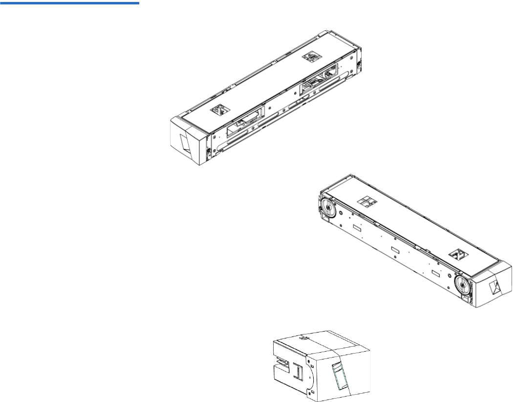
Chapter 7 Customer Replaceable Units (CRUs)
Replacing a Magazine or Magazine Blank
Quantum SuperLoader 3 User’s Guide 91
Figure 9 Left Magazine
Changing the orientation of a magazine 7
1Remove the two screws that attach the handle to the front of the
magazine.
Inside edge view of left
magazine
Outside edge view of left
magazine
Left magazine blank
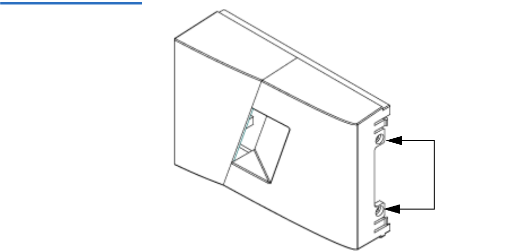
Chapter 7 Customer Replaceable Units (CRUs)
Replacing a Magazine or Magazine Blank
Quantum SuperLoader 3 User’s Guide 92
Figure 10 Removing the
Screws from the Handle
2Unsnap the handle carefully, being careful not to break the hinge.
3Rotate the magazine 180 degrees so that what was the front of the
magazine is now the back.
4Attach the appropriate left or right handle to the front of the rotated
magazine.
5Snap the handle back onto the front of the magazine.
6Install the two screws to attach the handle securely to the magazine.
Changing the orientation of a magazine blank 7
1Remove the two screws that attach the handle to the front of the
magazine blank.
2Unsnap the handle carefully, being careful not to break the hinge.
3Rotate the magazine blank 180 degrees so that what was the front of
the magazine is now the back.
4Add the appropriate right or left handle to the front of the rotated
magazine blank.
5Snap the handle back on the front of the magazine blank.
Screws

Chapter 7 Customer Replaceable Units (CRUs)
Rack Mounting the Autoloader
Quantum SuperLoader 3 User’s Guide 93
6Install the two screws to attach the handle securely to the magazine
blank.
Rack Mounting the Autoloader
The autoloader can be rack mounted directly to the stationary cabinet
rails.
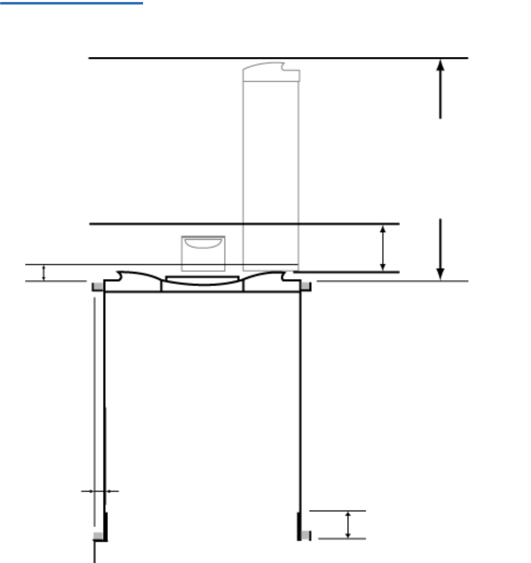
Chapter 7 Customer Replaceable Units (CRUs)
Rack Mounting the Autoloader
Quantum SuperLoader 3 User’s Guide 94
Figure 11 Clearance
Requirements for Rack
Mounting
Minimum clearance to load or
unload a magazine from the
system
Minimum clearance to load a
tape via the mailslot
Clearance to door inside a rack
27.0” [686 mm]
6.0” [152 mm]
2.0” [51 mm]
1.0” [25 mm]
3.4” [86 mm]
Minimum side
clearance (both
sides)
FRONT
REAR
Minimum clearance between
the rear of the SuperLoader
and the inside of the rack
(using standard mounting
brackets adjusted to their
closest setting)

Chapter 7 Customer Replaceable Units (CRUs)
Rack Mounting the Autoloader
Quantum SuperLoader 3 User’s Guide 95
General Preparation for
Rack Mount Installation 7Take the following general safety steps before beginning a rack mount
installation.
1Lower the cabinet feet.
2Extend the cabinet anti-tip device, if available.
3Ensure that the cabinet and all rack mounted equipment have a
reliable ground connection.
4Verify that the total current of all rack mounted components
(including the SuperLoader) will not exceed the current rating of the
power distribution unit or outlet receptacles.
5Secure the help of at least one other person. At least two people are
required to safely install the SuperLoader into a rack cabinet.
Stationary Rack Mount
Installation 7This section describes the steps for attaching the autoloader directly to
the stationary rails of a rack.
1Make sure you have the following tools and parts:
• #2 Phillips screwdriver
• Level
• The following autoloader accessory kit parts (see figure 12):
• Four autoloader brackets (two long and two short to
accommodate different rack depths)
Use the short autoloader brackets (74-60604-03) unless the
distance from the front mounting rail to the rear mounting
rail is less than 30.25 in. (76.84 cm).
• Two support brackets (74-60605-01)
• Eight 10-32 x 1/4 inch button head screws for the support
brackets (four per support bracket)
Warning: Failure to take these safety steps may result in
personal injury or equipment damage.
Caution: Do not remove the top cover of the autoloader during
the installation process. Removing the top cover could
result in damage to the autoloader.
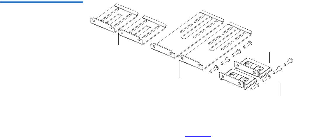
Chapter 7 Customer Replaceable Units (CRUs)
Rack Mounting the Autoloader
Quantum SuperLoader 3 User’s Guide 96
• The following parts shipped with your rack and are not supplied
by Quantum:
• Eight clip nuts
•Eight screws
Figure 12 Required Parts for
Installation
2Install two clip nuts, 1.75 in. (44.45 mm) apart, onto each of the four
rails of the rack, making sure that you install each pair of clip nuts at
exactly the same level (see figure 13).
Support brackets
Support bracket screws
Long autoloader
brackets (74-60604-01)
Short autoloader
brackets (74-60604-03)
(74-60605-01)
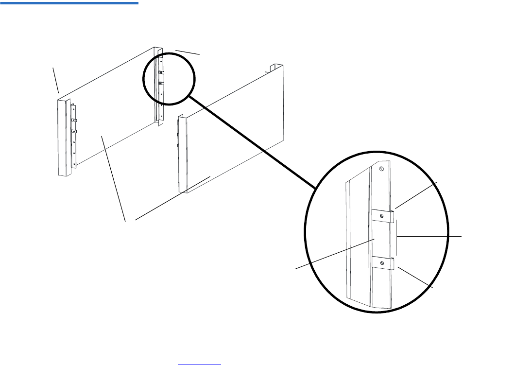
Chapter 7 Customer Replaceable Units (CRUs)
Rack Mounting the Autoloader
Quantum SuperLoader 3 User’s Guide 97
Figure 13 Installing Two Clip
Nuts
3Select the long or short autoloader brackets (depending on the depth
of the rack), and then attach them to the rear of the autoloader (see
figure 14).
Clip nut
Outer covers
of the rack
Rail Rail
Rail
1.75 in
(44.45 mm)
Clip nut
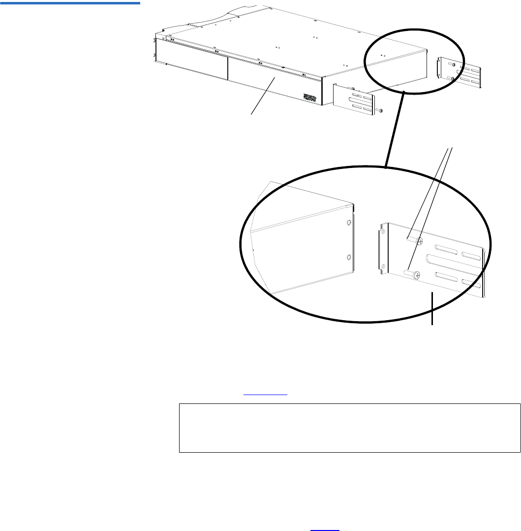
Chapter 7 Customer Replaceable Units (CRUs)
Rack Mounting the Autoloader
Quantum SuperLoader 3 User’s Guide 98
Figure 14 Attaching Autoloader
Brackets
4Using rack screws, attach a support bracket to the clip nuts on each
rear rail (see figure 15.)
Tighten the screws just enough to hold the support brackets firmly
against the rail while still allowing the support bracket to be slightly
shifted by hand. This shifting will help facilitate the engagement of
autoloader brackets as the autoloader is installed in the rack. You will
fully tighten the screws in step 8.
Note: Be sure to attach the support brackets correctly; the side of
the bracket with only two holes should be secured to the
rail.
Autoloader bracket
Screws (10-32 x 1/4 only)
Autoloader
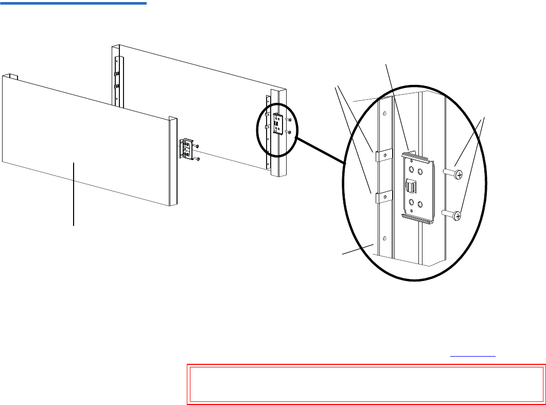
Chapter 7 Customer Replaceable Units (CRUs)
Rack Mounting the Autoloader
Quantum SuperLoader 3 User’s Guide 99
Figure 15 Attaching Support
Brackets
5With the help of a second installer, insert the autoloader into the rack
so that the autoloader brackets slide into corresponding support
brackets on the rear rails and the tabs at the front of the autoloader
align flush with the clip nuts on the front rails (see figure 16).
Caution: Do not release the front end of the autoloader until it
can be secured to the rack.
Outer cover of rack
Rear rail in rack
Support bracket
Clip nuts
Rack
screws
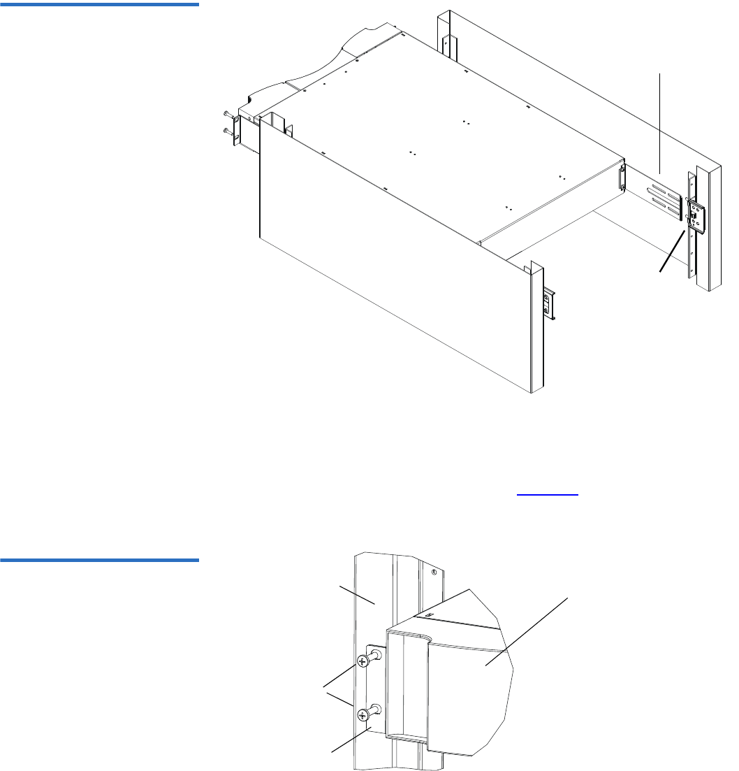
Chapter 7 Customer Replaceable Units (CRUs)
Rack Mounting the Autoloader
Quantum SuperLoader 3 User’s Guide 100
Figure 16 Sliding Autoloader
into Rack
6While the other installer holds the front end of the autoloader, secure
the autoloader in the rack by doing the following:
aSecure the front end of the autoloader to the rack using four rack
screws (two per tab) as shown in figure 17. Tighten the screws
just enough to secure the autoloader to the front rails.
Figure 17 Front Alignment
Support bracket
Autoloader bracket
Front rail
Tab (one
Autoloader (front)
Rack
screws
per side)
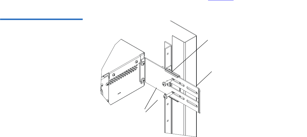
Chapter 7 Customer Replaceable Units (CRUs)
Rack Mounting the Autoloader
Quantum SuperLoader 3 User’s Guide 101
bInstall four screws (two per side) to secure the support brackets
to the autoloader brackets (see figure 18).
Figure 18 Connecting Support
Brackets
7Verify that the autoloader is level. Adjust as needed.
8When the autoloader is level, tighten all screws securing the
autoloader to the rack. This includes the following:
• Four screws securing the autoloader tabs to the front rails.
• Four screws securing the support brackets to the rear rails.
• Four screws securing the autoloader brackets to the support
brackets.
Autoloader
Support bracket
bracket
Screws

Quantum SuperLoader 3 User’s Guide 102
Chapter 8
8Logs and Troubleshooting
This chapter covers information about logs and troubleshooting of the
autoloader. The following topics are available:
•Before Contacting Customer Support
•“Autoloader Logs” on page 106
•“Tape Drive Logs” on page 120
•“POST Failure Logs” on page 121
•“Returning the Autoloader for Service” on page 122
Before Contacting Customer Support
Errors that you may experience with your autoloader can range from
severe hardware damage to simple connection problems. Before you
return your autoloader, you may be able to fix the problem yourself by
following some basic troubleshooting procedures.
Other than drive cleaning, there is no recommended routine maintenance
for the Quantum SuperLoader 3 autoloader.
The front LCD provides some troubleshooting capabilities, but is limited.
On-board Remote Management provides more detailed information

Chapter 8 Logs and Troubleshooting
Before Contacting Customer Support
Quantum SuperLoader 3 User’s Guide 103
about the present state of the autoloader and past performance, and is
more helpful for troubleshooting errors.
Table 9 describes the probable cause and suggested action for problems
that you may encounter.
Table 9 Probable Cause and
Possible Solutions
Warning: The SuperLoader 3 is not intended for customer servicing.
If you do service the unit yourself, the power cable must
be removed from the unit and the electrical outlet before
removing the cover. Failure to do so may cause severe
bodily injury or damage to the equipment.
Problem Suggested Action
The front panel does not display information. The connection to the LCD has failed.
• Use On-board Remote Management to
troubleshoot error.
The user starts a code update from the front panel
without inserting a tape.
• Power cycle the unit.
The autoloader does not respond on the front
panel SCSI bus or Ethernet. Bug checks appear
immediately after loading a new version of
firmware.
The firmware is corrupted.
• Reload the firmware.
The autoloader is operating slowly. The autoloader is incorrectly configured for the
operating system.
•Go to www.quantum.com for compatibility
requirements.
The autoloader does not turn on. The power cable or source is malfunctioning. The
autoloader is incorrectly configured.
• Check all outlets and power cables for proper
connection.
• Contact customer support.

Chapter 8 Logs and Troubleshooting
Before Contacting Customer Support
Quantum SuperLoader 3 User’s Guide 104
The front panel and light indicators do not turn
on.
• Verify that the autoloader is plugged in.
• Verify that the power switch on the back is
turned on.
• Verify that the drive carrier assembly is locked
into the autoloader chassis with the four screws
supplied.
• Contact customer support.
The front panel does not display information, but
light indicators above the front panel are turned
on.
• Connect to the autoloader, using On-board
Remote Management with an Ethernet
connection and issue a System Reset from the
Diagnostics page.
• Verify that the drive carrier assembly is locked
into the autoloader chassis with the four screws
supplied.
• On the front panel, press and hold the power
switch for 15 seconds, then turn the rear power
switch off. Wait 60 seconds and turn the rear
power switch back on.
• Contact customer support.
The autoloader does not communicate with the
host system via the SCSI bus.
• Verify that the SCSI cables are connected to the
rear of the autoloader and that the correct LVD
host controller card is installed.
• Verify that the SCSI cables are not damaged or
crimped and the total SCSI cable length is not
exceeding the maximum required length.
• Verify that a LVD SCSI terminator is attached
to both the first and last SCSI device on the
SCSI bus.
• Verify that the autoloader SCSI ID is set to a
unique SCSI ID that is not used by any other
SCSI device on the same SCSI bus.
• Issue a System Reset either by using On-board
Remote Management Diagnostic page or by
turning off power from the front panel.
• Contact customer support.

Chapter 8 Logs and Troubleshooting
Before Contacting Customer Support
Quantum SuperLoader 3 User’s Guide 105
The tape drive responds on the SCSI bus to the
host, but the autoloader does not respond.
• Verify that the autoloader LUN is set to 1. To
do this, select Status on the LCD front panel,
then select Drive, and then Status.
• Go to the Configuration menu and verify that
the mode is set to Random.
• If the SCSI ID is unique, check SCSI cables and
terminators.
• Verify that the host application and the device
drivers are installed with the most current
patches to support the autoloader.
The autoloader does not communicate with the
host system via the Ethernet.
• Verify that the Ethernet cable is connected to
the correct hub.
• Verify the Ethernet configuration settings via
the front panel LCD. If the DHCP server is
available, Ethernet status should indicate
DHCP, otherwise, you must set a unique IP
address and a subnet mask.
• Power off the autoloader by turning off the
system from the front panel LCD and turning it
back on.
• Contact customer support.
The application software reports a failure locating
a piece of media or fails to move a piece of media
as requested.
• Use the On-board Remote Management tool
and verify that the media is in the expected
location internal to the autoloader.
• Issue a System Reset either by using On-board
Remote Management Diagnostics page System
Reset, or by turning the power off from the
front panel.
• Contact customer support.
The application software reports an error while
reading or writing a piece of media.
• Try a different piece of media.
• Issue a System Reset either by using On-board
Remote Management Diagnostics page System
Reset, or cycle the power from the front panel.
• Contact customer support.

Chapter 8 Logs and Troubleshooting
Autoloader Logs
Quantum SuperLoader 3 User’s Guide 106
Autoloader Logs
Whenever any system or application actions occur, the autoloader
generates logs recording the action. You can use some of these logs to
troubleshoot errors. Errors are problems that occur while operating the
autoloader. They prevent the autoloader from completing a specific
action.
When an error occurs, one of the following can happen and the system
generates a log of the error:
• No error message appears, but the autoloader fails to complete the
action.
• An error message appears on the front panel or in the On-board
Remote Management screen. The screen displays the error message
and the Hard Log records non-recoverable errors (see “Hard Logs” on
page 108).
You can use these error logs to determine the type of error, when it
occurred, and what parts of the autoloader it affects (or which parts of the
autoloader need to be repaired or replaced).
Different types of error logs are generated for the autoloader and the tape
drive.
• Autoloader error logs provide information if the errors relate to data
cartridge movement.
Other failures occur. • Issue a System Reset either by using On-board
Remote Management Diagnostics page System
Reset, or cycle the power from the front panel.
• Contact customer support.
Note: To troubleshoot hard errors, you may need to power cycle,
repair, or replace the unit.

Chapter 8 Logs and Troubleshooting
Autoloader Logs
Quantum SuperLoader 3 User’s Guide 107
• Tape drive error logs provide information if the errors relate to the
tape drive's read/write performance.
Log Types 8While there are other types of logs, use the Hard Log to troubleshoot
errors. This log helps determine the type of error, time of occurrence, and
parts of the autoloader affected.
The autoloader generates the following logs, all with the same basic
format (see “Hard Log Example” on page 109):
Soft Logs 8
The Soft Log records the autoloader's history during different conditions.
It is similar to the Hard Log but may have been overwritten by a recovery
action.
Update Logs 8
The Update Log records firmware changes and upgrades in the
autoloader. It also records information when hardware is updated or
changed.
Shadow Logs 8
(Engineering use only)
Boot Logs 8
The Boot Log keeps track of the boot status in terms of number of hours
the unit has been powered on, the number of times the autoloader has
been rebooted, and the reason for the reboot.
OEM Logs 8
OEM Logs store information specific to an OEM.

Chapter 8 Logs and Troubleshooting
Autoloader Logs
Quantum SuperLoader 3 User’s Guide 108
ID Logs 8
ID Logs store information specific to an OEM.
Hard Logs 8
The Hard Log is used for troubleshooting purposes and is described in
Retrieving the Hard Log. Entries in the Hard Log represent errors that
were not recovered during normal retry operations.
The following table indicates the ways in which you can retrieve each log
type.
Table 10 Log Retrieval
Methods
Each log records information such as time of the event, error codes, and
context information. The key fields are the “Time Stamp” on page 110 (in
order to correlate the event with a possible application interruption), and
the “Error Type” on page 112 for which the event was logged.
Retrieving the Hard Log 8Partial information from the Hard Log can be retrieved from the front
panel. The front panel displays only the most important information.
You can retrieve complete Hard Log information through On-board
Remote Management.
Log Type http Front Panel SCSI
Soft Yes Yes No
Update Yes Yes No
Shadow Yes No No
Boot Yes No No
OEM Yes No Yes
ID Yes No Yes
Hard Yes Yes Yes

Chapter 8 Logs and Troubleshooting
Autoloader Logs
Quantum SuperLoader 3 User’s Guide 109
Whenever the autoloader generates a Hard Log, On-board Remote
Management automatically displays the log information. For front panel
retrieval, you must request the information.
By interpreting the information in this log, you can determine how to
troubleshoot errors.
To retrieve Hard log information from the front panel: 8
1From the front panel LCD, scroll to Diagnostics, and then press Enter.
The Diagnostics submenu displays.
2From the Diagnostics submenu, scroll to Error Logs, and then press
Enter. The Error Log submenu displays.
3From the Error Logs submenu, scroll to Hard, and then press Enter.
The log information displays.
To retrieve Hard log information from On-board Remote
Management: 8
1From any screen, click the Diagnostics heading. The Diagnostics
screen displays.
2Click View Logs.
3If you want to save logs to your hard drive, click Save Logs. If you
save a log to a file, you must select a destination folder within 60
seconds.
Hard Log Example 8The first line of the Hard Log shows the number of entries, queue size, and
defines the queue wrap and erase parameters.
The first line of each Hard Log event contains the information you are
looking for. The highest number entry, shown at the bottom of the queue,
contains the most recent event.
You are interested primarily in the time stamp and error fields. Context
information followed by the 12 double-words are for engineering use
only and cannot be interpreted without firmware source code.

Chapter 8 Logs and Troubleshooting
Autoloader Logs
Quantum SuperLoader 3 User’s Guide 110
**** Hard Log ****
Block 1, 004/016 entries @ 64 bytes each, wrap @ 004, erase @ 008
0000: 2001-Jun-27, 17:24:06.001, Error: 002f0222, Context: 4802/00000000
65460621:00610004:ffffffff:ffffffff
ff741e03:0075ff63:0566063f:007f0000
ffffffff:ffffffff:ffffffff:ffffffff
0001: 2001-Jun-27, 17:24:08.036, Error: c02f0223, Context: 4802/00000000
00000000:00000000:00000000:00000000
00000000:00000000:00000000:00000000
00000000:00000000:00000000:00000000
0002: 2001-Jun-27, 17:38:19.777, Error: 002f0222, Context: 4802/00000000
65460621:00610004:ffffffff:ffffffff
ff741e03:0075ff63:0566063f:007f0000
ffffffff:ffffffff:ffffffff:ffffffff
0003: 2001-Jun-27, 17:38:21.812, Error: c02f0223, Context: 4802/00000000
00000000:00000000:00000000:00000000
00000000:00000000:00000000:00000000
00000000:00000000:00000000:00000000
Time Stamp 8The time the event occurred. This field helps correlate the event with a
possible application interruption.
If the unit is unable to acquire the correct time/date from the SNTP time
server or the front panel, the time stamp contains values indicating the
power cycle number and the time an entry was written relative to that
power cycle, listed as Power On Hours (POH).
Note: The unit has no internal real-time clock and requires you to set
the time of day from the front panel or the network interface
(SNTP).

Chapter 8 Logs and Troubleshooting
Autoloader Logs
Quantum SuperLoader 3 User’s Guide 111
Error Fields 8The error fields are defined as follows:
Recovery Action 8
Recovery Action defines what the autoloader will do based on the event
that occurred.
•If the value is 0, the autoloader continues operations. These events are
typically soft recoverable events or events that are just recording an
action for when the development team is working on enhancements.
•If the value is nonzero, the autoloader must reboot in order to recover
from the event. The reboot happens automatically.
Task ID 8
Task ID defines what firmware task was being performed at the time of
the event.
Bits 31, 30
Bits
29-28
Bits
27-24
Bits
23-20
Bits
19-16
Bits
15-12
Bits
11-8
Bits
7-4
Bits
3-0
Recovery Action Task ID Error Type Context Information
Task ID Description
00 System Timer
01 Loader Manager
02 Picker
03 Magazine Left
04 Magazine Right
05 Magazine Up Left
06 Magazine Up Right

Chapter 8 Logs and Troubleshooting
Autoloader Logs
Quantum SuperLoader 3 User’s Guide 112
Error Type 8
Error Type defines the type of error and the action to which the event is
related. This field helps identify what caused the event to occur.
07 Drive Manager
08 Bar Code Reader
09 Front Panel
0A IP
0B Diagnostic
0C Error
0D Code Update
0E ADI
0F Drive Manager Timer
11 HTTP
12 SNTP
20 Idle
3E Watch Dog Timer
3F Un-handle Interrupt
Task ID Description

Chapter 8 Logs and Troubleshooting
Autoloader Logs
Quantum SuperLoader 3 User’s Guide 113
Table 11 Error Type Listing
and Suggested Actions
Error Type Description Suggested Actions
00–25 General Software flags • Check for a Hard Error log. If an error displays in the
Hard Error log, power cycle the autoloader.
•Check www.quantum.com for firmware updates.
• If all previous steps fail, contact customer support.
26 Message Send ID error • Check the SCSI bus cables and terminators.
• Check the host adapter.
• Power cycle the autoloader. Repeat checks after
power cycle.
• If all previous steps fail, contact customer support.
27 Message Bad • Check the SCSI bus cables and terminators.
• Check the host adapter.
• If all previous steps fail, contact customer support.
28 Message parameter Bad • Check the host device driver.
• Check the host application.
• Check the SCSI bus cables and terminators.
• Check the host adapter.
• Power cycle the autoloader. Repeat checks after
power cycle.
• If all previous steps fail, contact customer support.
29 Invalid Element • Check the host device driver.
• Check the host application.
• Power cycle the autoloader. Repeat checks after
power cycle.
• If all previous steps fail, contact customer support.

Chapter 8 Logs and Troubleshooting
Autoloader Logs
Quantum SuperLoader 3 User’s Guide 114
2A Invalid Element Status • Check the host device driver.
• Check the host application.
• Power cycle the autoloader. Repeat checks after
power cycle.
• If all previous steps fail, contact customer support.
2B–2F Firmware tables and stacks
invalid
• Check for a Hard Error log. If an error displays in the
Hard Error log, power cycle the autoloader.
•Check www.quantum.com for firmware updates.
30 POST Failure • Verify that the magazines are fully seated.
• Power cycle.
• If all previous steps fail, contact customer support.
31–38 System Monitoring type
events
• Check for a Hard Error log. If an error displays in the
Hard Error log, power cycle the autoloader.
•Check www.quantum.com for firmware updates.
• If all previous steps fail, contact customer support.
3A Drive Error • Check the Drive Log Sense for drive errors. If the
drive is still logging errors, contact customer support.
• If the drive is logging try a different piece of media.
• If the drive fails with two different pieces of media,
contact customer support.
3B Drive Hardware Err • Clean the drive.
• Try another piece of media.
• If the drive fails with two different pieces of media,
contact customer support.
3C Drive Needs Cleaning • Perform drive cleaning using a valid cleaning
cartridge.
Error Type Description Suggested Actions

Chapter 8 Logs and Troubleshooting
Autoloader Logs
Quantum SuperLoader 3 User’s Guide 115
3D Drive Error • Check the Drive Log Sense for drive errors. If the
drive is still logging errors, contact customer support.
• If the drive is logging try a different piece of media.
• If the drive fails with two different pieces of media,
contact customer support.
3E Load Error • Verify that the cartridge does not have labels or other
matter anywhere on the cartridge except where labels
are expected to be placed.
• Try to load a different piece of media.
• If multiple pieces of media fail, contact customer
support.
3F Unload Error • Verify that the cartridge does not have labels or other
matter anywhere on the cartridge except where labels
are expected to be placed.
• Try to load a different piece of media.
• If multiple pieces of media fail, contact customer
support.
49 Offline • No action required.
4A Door Locked • No action required.
4B Open Front • Install the magazine or magazine blank.
• Replace the magazine or magazine blank (try a
second one if possible).
• If all previous steps fail, contact customer support.
4C Over Temp • Verify that the temperature of the autoloader inlet air
is within specifications.
• Clear debris from any opening of the autoloader,
both in front and in the back.
• Verify that both fans are working. If fans are bad,
contact customer support.
Error Type Description Suggested Actions

Chapter 8 Logs and Troubleshooting
Autoloader Logs
Quantum SuperLoader 3 User’s Guide 116
60–69 Internal communications
events
• Power cycle.
• If the previous step fails, contact customer support.
A0–A4 Picker Servo Errors • If repeated events appear in the Hard Errors log,
power cycle the autoloader. Repeat test after power
cycle.
• If all previous steps fail, contact customer support.
A5 Source Element Empty • Verify that the expected source really does have a
cartridge.
•If the source is a magazine, replace the cartridge in
that slot with a different cartridge and try again. If
error continues, replace the magazine.
• If source is the tape drive, verify the tape drive has a
cartridge and it was ejected.
• Power cycle the autoloader.
• If the error continues, contact customer support.
A6 Source Magazine Missing • Verify that the magazine is installed correctly into the
autoloader.
• Remove and reinsert the magazine again.
• Try a second magazine, if possible.
• Power cycle the autoloader.
• If the error continues, contact customer support.
A7 Mailslot full • Verify that the magazine is installed correctly in the
autoloader.
• Remove and reinsert the magazine again.
• Try a second magazine, if possible.
• Power cycle the autoloader.
• If all previous steps fail, contact customer support.
Error Type Description Suggested Actions

Chapter 8 Logs and Troubleshooting
Autoloader Logs
Quantum SuperLoader 3 User’s Guide 117
A8 Destination Element Full • Verify the expected destination really does not have a
cartridge.
• If destination is a magazine, install and remove a
cartridge from the selected slot and try again. If error
continues, replace the magazine.
• If destination is the tape drive, verify the tape drive
does not have a cartridge.
• Power cycle the autoloader.
• If error continues, contact customer support.
• If the cartridge is in the mailslot opening, remove it.
• Verify that the mailslot is fully closed.
• Verify that there is no debris in the mailslot opening.
A9 Picker Full • Look in the front of the autoloader and confirm that
the picker is full.
• Contact customer support.
AA Picker Cartridge Sensor Error • Look in the front of the autoloader and confirm the
picker is full.
• Contact customer support.
AB Drive Path Sensor Error • Power cycle the autoloader.
• Contact customer support.
AC Mail Slot Door Sensor Error • Insert a cartridge into the autoloader via the mailslot.
• Power cycle the autoloader.
• If all previous steps fail, contact customer support.
AD Mail Slot Solenoid Error • Insert a cartridge into the autoloader via the mailslot.
• Power cycle the autoloader.
• If all previous steps fail, contact customer support.
AE Unknown Servo Error • Contact customer support.
AF Error Log Information Event • No action required.
Error Type Description Suggested Actions

Chapter 8 Logs and Troubleshooting
Autoloader Logs
Quantum SuperLoader 3 User’s Guide 118
B0–BF Error Events related to the
picker not rotating or
translating properly
• Power cycle the autoloader.
• Contact customer support.
C0 Unknown Motor Error • Power cycle the autoloader.
• Contact customer support.
D0 Magazine Solenoid Bad • Check the Task ID in the Hard Error log to determine
if the problem is the right or the left magazine.
• Remove and reinsert the magazine. Verify that the
magazine slides freely, and clicks and locks into
place.
• Power cycle the autoloader.
• Try a different magazine.
• If all previous steps fail, contact customer support.
D1 Magazine Present Sensor Bad • Check the Task ID in the Hard Error log to determine
if the problem is the right or the left magazine.
• Remove and reinsert the magazine.
• Power cycle the autoloader.
• Make sure that the sensor is not blocked by debris.
• If all previous steps fail, contact customer support.
D2–D4 Position Sensor Bad • Check the Task ID in the Hard Error log to determine
if the problem is the right or the left magazine.
• Remove and reinsert the magazine.
• Try a different magazine, if possible.
• Power cycle the autoloader.
• If all previous steps fail, contact customer support.
Error Type Description Suggested Actions

Chapter 8 Logs and Troubleshooting
Autoloader Logs
Quantum SuperLoader 3 User’s Guide 119
Context Information 8
Context Information followed by the 12 double-words are for
engineering use only and cannot be interpreted without firmware
source code.
D5–DE Cartridge flags located on the
magazine may be bad or the
sensor to detect the flags may
have a problem.
•Check the Task ID in the Hard Error log to determine
if the problem is the right or the left magazine.
• Remove and reinsert the magazine.
• Try a different magazine, if possible.
• Make sure that the sensor is not blocked by debris.
• Power cycle the autoloader.
• If all previous steps fail, contact customer support
DF Jammed Cartridge • Check the Task ID in the Hard Error log to determine
if the problem is the right or the left magazine.
• Power cycle the autoloader.
• Disconnect all data cables from the autoloader.
• Power cycle the autoloader.
• Use the following OCP commands:
Commands
Eject
Tape - Mailslot
From Drive
• If all previous steps fail, contact customer support
Error Type Description Suggested Actions

Chapter 8 Logs and Troubleshooting
Tape Drive Logs
Quantum SuperLoader 3 User’s Guide 120
Tape Drive Logs
The tape drive generates six types of logs (see “Tape Drive Error Logs” on
page 146). For troubleshooting errors, you will only use SCSI Check
Condition Error logs, Bugcheck Error logs, and Event Error logs.:
•“SCSI Check Condition Error Logs” on page 147
•“Bugcheck Error Logs (SDLT 600 only)” on page 150
•“Event Error Logs (SDLT 600 only)” on page 152
Log Fields 8The logs contain three main fields:
Table 12 Log Field
Descriptions Field Description
Event Log Number A sequence number that indicates the order in
which the event was logged.
Event Number or
Name
This field appears in every event log, but
varies depending on the event type. This field
indicates the type of log.
POH/PC The tracking information for how many
power-on-hours (POH) the drive has had
since it was shipped. This is how many hours
the drive has had power applied regardless of
the number of times it is turned on and off.
POH is updated once every 60 minutes the
drive has had power applied with no
interruptions.
Power cycles (PC) is how many times the
drive has experienced a POC. Each time a
drive logs a Hard Event, it will increment this
count as well.
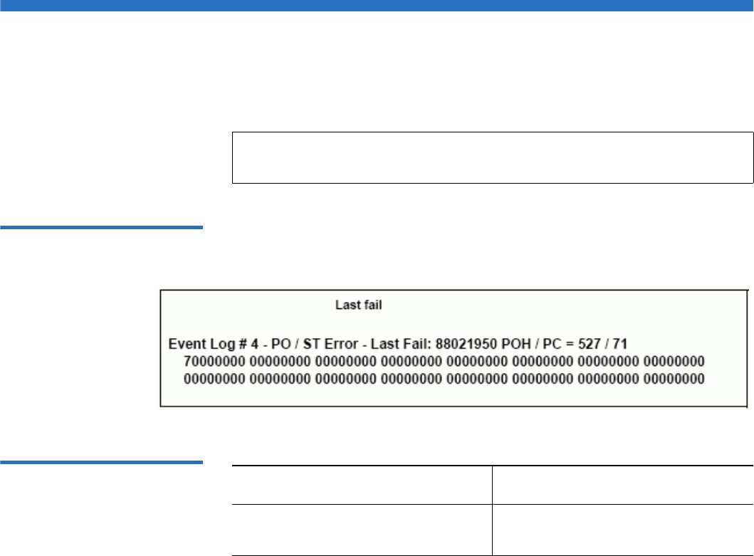
Chapter 8 Logs and Troubleshooting
POST Failure Logs
Quantum SuperLoader 3 User’s Guide 121
POST Failure Logs
These events indicate that the autoloader or tape drive detected a failure
when power was applied. POST may have failed during a reset and retry.
Figure 19 POST Failures
Event Log Sample
Table 13 POST Failure
Specific Fields
Note: This event type only indicates each time the test ran and
experienced the error condition.
Field Description
Last Fail The type of failure that was
experienced.

Chapter 8 Logs and Troubleshooting
Returning the Autoloader for Service
Quantum SuperLoader 3 User’s Guide 122
Returning the Autoloader for Service
If you need to return the autoloader to the factory for service, first verify
which customer replaceable unit (CRU) that you need to return and
return only that CRU, not the entire autoloader.
Once you determine the CRU to replace, contact customer support to
obtain return material authorization (RMA) and shipping information.
When you have the RMA number, use the following procedure.
Preparing the Autoloader
for Shipment 8If you must return the complete autoloader for service, use these steps to
prepare the autoloader for shipment.
1Remove all cartridges from the unit.
2Power off the autoloader via the front panel.
3Remove the power, Ethernet, and SCSI cables, and any terminators
from the autoloader.
Removing the Autoloader
from a Rack 8To remove the autoloader from a rack:
1Loosen the four screws that connect the two support brackets to the
two autoloader brackets.
2Loosen the four screws on the front of the autoloader that attach the
two front tabs (support brackets) to the front rails. Do not remove the
screws completely at this time.
3Remove the four screws at the back of the autoloader that connect the
support brackets (two screws per bracket) to the autoloader brackets.
4While supporting the front of the autoloader, remove the four front
screws.
Note: Do not ship these items if you are returning the autoloader
to the factory.
Warning: Injury may occur if the unit is not supported when
you remove the front screws. The screws are holding
up the front of the unit.

Chapter 8 Logs and Troubleshooting
Returning the Autoloader for Service
Quantum SuperLoader 3 User’s Guide 123
5Using two people, or an appropriately rated mechanical lift, remove
the autoloader from the rack by sliding the autoloader out and
supporting it from the bottom. The person handling the back of the
unit must depress the locking tab on the support bracket while
sliding the unit forward.
6Loosen the four screws and remove the autoloader brackets from the
back of the autoloader.
7Place the autoloader into the original packaging box. If you no longer
have the original packaging, contact your service representative to
purchase the packaging kit.
Packing the Autoloader 8Use the original packing material to pack the autoloader: the shipping
container, two foam insert packing pieces, the accessory kit box (or the
filler tube if your autoloader did not come with an accessory kit box), and
the antistatic bag. You will also need packing tape.
1Place the antistatic bag over the autoloader.
2Place one of the foam endcaps onto one side of the autoloader. Place
the second foam insert onto the other side of the autoloader and
make sure the pieces fit snugly onto the autoloader.
3Place the autoloader down into the shipping box and push the back
of the autoloader towards the back end of the box.
4Insert the empty accessory kit box (or filler tube) into the shipping
box at the front end of the autoloader in the space between the
autoloader foam inserts and the shipping container.
5Place any necessary paperwork on top of the autoloader inside the
box.
6Close and seal the box.
7Place the shipping label on the box.
8Ship the box.
Note: One end of the foam insert has a curved piece. This end of
the foam insert is designed to fit the front of the
autoloader.

Quantum SuperLoader 3 User’s Guide 124
Appendix A
ASpecifications
This appendix describes the Autoloader Specifications relating to the
SuperLoader 3 equipped with one of the following drives:
•LTO-2 Drive Specifications
•LTO-3 Drive Specifications
•LTO-4 Drive Specifications
•SDLT 600 Drive Specifications
•DLT-V4 Drive Specifications
•SDLT 600 Drive Specifications
•DLT-S4 Drive Specifications

Autoloader Specifications
Quantum SuperLoader 3 User’s Guide 125
Autoloader Specifications
Rack Mount
Height 8.9 cm (3.5 in.)
Width 45 cm (17.7 in.)
Length 75.46 cm (29.71 in.)
Package Weight
(without media)
22.7 kg (50 lb.)
Footprint 0.32 square meters (3.4 square feet)

Autoloader Performance Specifications
Quantum SuperLoader 3 User’s Guide 126
Autoloader Performance Specifications
Maximum data transfer rate LTO-2 Drive
Native: 93.6 GB/hr.
Compressed: 187.2 GB/hr. (assuming 2:1 compression ratio)
LTO-3 Drive
Native: 245 GB/hr.
Compressed: 490 GB/hr. (assuming 2:1 compression ratio)
LTO-4 Drive
Native: 432 GB/hr.
Compressed: 864 GB/hr. (assuming 2:1 compression ratio)
VS160 Drive
Native: 28.8 GB/hr.
Compressed: 57.6 GB/hr. (assuming 2:1 compression ratio)
DLT-V4 Drive
Native: 36 GB/hr.
Compressed: 72 GB/hr. (assuming 2:1 compression ratio)
SDLT 600 Drive
Native: 129.6 GB/hr.
Compressed: 259.2 GB/hr. (assuming 2:1 compression ratio)
DLT-S4 Drive
Native: 216 GB/hr.
Compressed: 432 GB/hr. (assuming 2:1 compression ratio)
Drive Type
(only one type per unit, not
interchangeable)
1 Quantum LTO-2 half-height drive, or
1 LTO-3 drive, or
1 LTO-4 drive, or
1 Quantum VS160 drive, or
1 Quantum DLT-V4 drive, or
1 Quantum SDLT 600 drive, or
1 Quantum DLT-S4 drive

Autoloader Performance Specifications
Quantum SuperLoader 3 User’s Guide 127
MCBF 400,000 cycles
Typical cycle time All Drive Types
< 40 seconds. One cycle consists of moving a cartridge from the
tape drive to a magazine slot, selecting another magazine slot,
and then moving the cartridge back to the tape drive. It does
not include the time that the tape drive takes to unload or
load/calibrate.
Average load time (after placing
cartridge in drive)
LTO-2 Drive (LTO Ultrium 2 cartridge)
12 seconds (to BOT for previously written tape)
40 seconds (to BOT with new tape)
LTO-3 Drive (LTO Ultrium 3 cartridge)
58 seconds (to BOT for previously written tape)
< 30 seconds (to BOT with new tape)
LTO-4 Drive (LTO Ultrium 4 cartridge)
62 seconds (to BOT for previously written tape)
< 19 seconds (to BOT with new tape)
VS160 Drive (VS1 cartridge)
120 seconds (to BOT for previously written tape)
150 seconds (to BOT with unformatted tape)
DLT-V4 Drive (DLTtape VS1 cartridge)
90 seconds (to BOT for previously written tape)
SDLT 600 Drive (SDLT II cartridge)
12 seconds (to BOT for previously written tape)
17 seconds (to BOT with new tape)
DLT-S4 Drive (DLTtape S4 cartridge)
20 seconds (typical)
40 seconds (unformatted media)

Autoloader Performance Specifications
Quantum SuperLoader 3 User’s Guide 128
Average unload time (from BOT) LTO-2 Drive = 19 seconds (from BOT)
LTO-3 Drive = < 30 seconds (from BOT)
LTO-4 Drive = < 19 seconds (from BOT)
VS160 Drive = 17 seconds (from BOT)
DLT-V4 Drive = 22 seconds (no brush, from BOT)
= 61 seconds (brush, from BOT)
SDLT 600 Drive = 12 seconds (from BOT)
DLT-S4 Drive = 19 seconds (from BOT)

Autoloader Environmental Specifications
Quantum SuperLoader 3 User’s Guide 129
Autoloader Environmental Specifications
Temperature Range (Dry Bulb)
Operating +10º to +35ºC
Nonoperating - 40ºC to +65ºC
Temperature Variation
Operating 10ºC per hour
Nonoperating 20ºC per hour
Humidity
Operating 20% to 80% noncondensing
Nonoperating 10% to 90% noncondensing
Gradient 10% per hour without condensation
Wet Bulb
Operating 26ºC max
Nonoperating 29ºC max
Altitude
Operating -153 m to 3048 m
Nonoperating -153 m to 12192 m

Autoloader Power Specifications
Quantum SuperLoader 3 User’s Guide 130
Autoloader Power Specifications
Autoloader Vibration Specifications
Line voltage All Drive Types
60 Hz system: 90–265 VAC
50 Hz system: 90–265 VAC
Maximum power All Drive Types
160W
Line frequency All Drive Types
47–63 Hz
AC Input current All Drive Types
60 Hz system: 4.0 A (RMS) for 115 VAC
50 Hz system: 2.0 A (RMS) for 230 VAC
Operating
Swept Sine Vibration 5–500 Hz, 0.25 G, 0.254 mm (0.01 in.) to smooth crossover,
1 8ve/min, (X, Y, Z) axes
Random Vibration 0.25 Grms, 5–500 Hz (X, Y, Z) axes
Non-Operating
Swept Sine Vibration 5–500 Hz, 0.75 G, 0.52 mm (0.02 in.) to smooth crossover,
1 8ve/min, (X, Y, Z) axes
Random Vibration 1.06 Grms, 5–500 Hz (X, Y, Z) axes

Autoloader Shock Specifications
Quantum SuperLoader 3 User’s Guide 131
Autoloader Shock Specifications
Tape Drive Specifications
The autoloader is equipped with one of the following drive types:
•LTO-2 Drive Specifications
•LTO-3 Drive Specifications
•LTO-4 Drive Specifications
•SDLT 600 Drive Specifications
•DLT-V4 Drive Specifications
•SDLT 600 Drive Specifications
•DLT-S4 Drive Specifications
Operating 3 G, 5 ms half-sine, 3 pulses (+/-) per axis, X, Y, Z
Non-Operating 20 G, 8 ms half-sine, 3 shocks (+/-) per axis, X, Y, Z

LTO-2 Drive Specifications
Quantum SuperLoader 3 User’s Guide 132
LTO-2 Drive Specifications
Media Capacity 1
Media Specifications 1
Description Quantum LTO-2
Read/write transfer rate: maximum
sustained (LTO Ultrium 2 media)
Noncompressed: 94 GB/hr.
Compressed (2:1 typical): 187 GB/hr.
Burst transfer rate 160 MB/s
Average access time 68 seconds (from BOT)
Loading time to BOT (for previously written
tape)
75 seconds (maximum)
Unloading time from BOT 30 seconds (maximum)
Media Type Capacity
LTO Ultrium 2 storage capacity Native: 3.2 TB with 16 cartridges
Compressed (2:1 typical): 6.4 TB with 16 cartridges
Characteristic LTO Ultrium 2
LTO Ultrium 2 formatted capacity 200 GB (noncompressed)
400 GB (2:1 typical compression)
Tape length 609 m (1998 ft.)
Cartridge dimensions 10.2 x 10.54 x 2.15 cm
(4 x 4.15 x .85 in)
Read compatibility LTO Ultrium 1, LTO Ultrium 2

LTO-2 Drive Specifications
Quantum SuperLoader 3 User’s Guide 133
Write compatibility LTO Ultrium 2 or
LTO Ultrium 1, LTO Ultrium 2
Shelf life > 30 years with < 10% loss in demagnetization @ 20°C
40% RH (noncondensing)
Cartridge life 1,000,000 passes (any point on the tape passing the
recording head in either direction)
LTO Universal Cleaning cartridge 20 uses
Characteristic LTO Ultrium 2

LTO-3 Drive Specifications
Quantum SuperLoader 3 User’s Guide 134
LTO-3 Drive Specifications
Media Capacity 1
Media Specifications 1
Description Quantum LTO-3
Read/write transfer rate: maximum
sustained (LTO Ultrium 3 media)
Noncompressed mode: 68 MB/s
Compressed (2:1 typical): 136 MB/s
Burst transfer rate 160 MB/s (maximum, native)
Average access time 58 seconds (from BOT)
Loading time to BOT (for previously written
tape)
75 seconds (maximum)
Unloading time from BOT 30 seconds (maximum)
Interface type Ultra 160 SCSI-3 LVD, or
Ultra 320 SCSI-3 LVD, or
Fibre Channel, or
SAS
Media Type Capacity
LTO Ultrium 3 storage capacity 6.4 TB with 16 cartridges
12.8 TB (2:1 typical compression) with 16 cartridges
Characteristic LTO Ultrium 3
LTO Ultrium 3 formatted capacity 400 GB (noncompressed)
800 GB (2:1 typical compression)

LTO-3 Drive Specifications
Quantum SuperLoader 3 User’s Guide 135
Basic description Pre-formatted (servo written) metal particle
Tape length 680 m (2230.9 ft.)
Cartridge dimensions 10.2 x 10.54 x 2.15 cm
(4 x 4.15 x .85 in)
Read compatibility LTO Ultrium 1, LTO Ultrium 2, LTO Ultrium 3
Write compatibility LTO Ultrium 2, LTO Ultrium 3
Shelf life > 30 years with < 10% loss in demagnetization @ 20°C
40% RH (noncondensing)
Cartridge life 1,000,000 passes (any point on the tape passing the
recording head in either direction)
LTO Universal Cleaning cartridge 20 uses
Characteristic LTO Ultrium 3

LTO-4 Drive Specifications
Quantum SuperLoader 3 User’s Guide 136
LTO-4 Drive Specifications
Media Capacity 1
Media Specifications 1
Description HP LTO-4
Read/write transfer rate: maximum
sustained (LTO Ultrium 4 media)
Noncompressed mode: 120 MB/s
Compressed (2:1 typical): 240 MB/s
Burst transfer rate 320 MB/s (maximum, native)
Average access time 62 seconds (from BOT)
Loading time to BOT (for previously written
tape)
< 19 seconds
Unloading time from BOT < 19 seconds
Interface type Ultra 320 SCSI-3 LVD, or
SAS
Media Type Capacity
LTO Ultrium 4 storage capacity 12.8 TB with 16 cartridges
25.6 TB (2:1 typical compression) with 16 cartridges
Characteristic LTO Ultrium 4
LTO Ultrium 4 formatted capacity 800 GB (noncompressed)
1600 GB (2:1 typical compression)
Basic description Pre-formatted (servo written) metal particle
Tape length 820 m (2690.2 ft.)

LTO-4 Drive Specifications
Quantum SuperLoader 3 User’s Guide 137
Cartridge dimensions 10.2 x 10.54 x 2.15 cm
(4 x 4.15 x .85 in)
Read compatibility LTO Ultrium 2, LTO Ultrium 3, LTO Ultrium 4
Write compatibility LTO Ultrium 3, LTO Ultrium 4
Shelf life > 30 years with < 10% loss in demagnetization @ 20°C
40% RH (noncondensing)
Cartridge life 1,000,000 passes (any point on the tape passing the
recording head in either direction)
LTO Universal Cleaning cartridge 20 uses
Characteristic LTO Ultrium 4

VS160 Drive Specifications
Quantum SuperLoader 3 User’s Guide 138
VS160 Drive Specifications
Media Capacity 1
Media Specifications 1
Description Quantum DLT VS160
Read/write transfer rate: maximum sustained
(VS1 media)
Noncompressed mode: 28.8 GB/hr
Compressed (2:1 typical): 57.6 GB/hr
Burst transfer rate 160 MB/s
Average access time 90 seconds (from BOT)
Loading time to BOT (for previously written
tape)
120 seconds (maximum)
Unloading time from BOT 25 seconds (maximum)
Interface type Low-voltage Differential (LVD) 16-bit Ultra, 160
SCSI-2
Media Type Capacity
VS1 storage capacity 5.1 TB (noncompressed) with 16 cartridges
10.2 TB (2:1 typical compression) with 16 cartridges
Characteristic Quantum DLT VS1
VS1 formatted capacity 80 GB (noncompressed)
160 GB (2:1 typical compression)
Basic description 0.498 inch (advanced metal particle)

VS160 Drive Specifications
Quantum SuperLoader 3 User’s Guide 139
Tape length 557.2 m (1847 ft.)
Cartridge dimensions 105.6 x 105.3 x 25.4 mm
(4.16 x 4.15 x 1.0 in)
Read compatibility DLT1, DLT VS80
Shelf life > 30 years with < 10% loss in demagnetization @
20°C
40% RH (noncondensing)
Cartridge life 10,000 load/unload threads
Cleaning cartridge life 20 uses
Characteristic Quantum DLT VS1

DLT-V4 Drive Specifications
Quantum SuperLoader 3 User’s Guide 140
DLT-V4 Drive Specifications
Media Capacity 1
Media Specifications 1
Description Quantum DLT-V4
Read/write transfer rate: maximum
sustained (SDLT II media)
Noncompressed: 36 GB/hr.
Compressed (2:1 typical): 72 GB/hr.
Burst transfer rate 160 MB/s
Average access time 84 seconds (from BOT)
Loading time to BOT (for previously written
tape)
70 seconds (maximum)
Unloading time from BOT 22 seconds (no brush)
61 seconds (brush)
Interface type Ultra 160 SCSI-3 LVD
Media Type Capacity
DLTtape VS1 storage capacity 5.1 TB (noncompressed) with 16 cartridges
10.2 TB (2:1 typical compression) with 16
cartridges
Characteristic VS1
DLTtape VS1 formatted capacity 160 GB (noncompressed)
320 GB (2:1 typical compression)
Basic description Metal particle

DLT-V4 Drive Specifications
Quantum SuperLoader 3 User’s Guide 141
Tape length 562.9 m (1,847 ft.)
Cartridge dimensions 10.41 x 10.41 x 2.54 cm
(4.1 x 4.1 x 1.0 in)
Read compatibility DLT-V4, DLT VS160, DLT VS80/DLT1
Write compatibility DLT-V4
Shelf life > 30 years with < 10% loss in demagnetization
@ 20°C
40% RH (noncondensing)
Cartridge life up to 200 uses
DLT VS1 Cleaning cartridge life 20 uses
Characteristic VS1

SDLT 600 Drive Specifications
Quantum SuperLoader 3 User’s Guide 142
SDLT 600 Drive Specifications
Media Capacity 1
Media Specifications 1
Description Quantum SDLT 600
Read/write transfer rate: maximum sustained
(SDLT II media)
Noncompressed mode: 129.6 GB/hr
Compressed (2:1 typical): 259.2 GB/hr
Burst transfer rate 160 MB/s
Average access time 79 seconds (from BOT)
Loading time to BOT (for previously written
tape)
40 seconds (maximum)
Unloading time from BOT 20 seconds (maximum)
Interface type Low-voltage Differential (LVD) 16-bit Ultra, 160
SCSI-3
Media Type Capacity
SDLT II storage capacity 4.7 TB (noncompressed) with 16 cartridges
9.4 TB (2:1 typical compression) with 16 cartridges
Characteristic SDLT II
SDLT II formatted capacity 300 GB (noncompressed)
600 GB (2:1 typical compression)
Basic description Advanced metal particle
Tape length 630 m (2,066 ft.)

SDLT 600 Drive Specifications
Quantum SuperLoader 3 User’s Guide 143
Cartridge dimensions 105.6 x 105.3 x 25.4 mm
(4.16 x 4.15 x 1.0 in)
Read compatibility SDLT I, SDLT II
Shelf life > 30 years with < 10% loss in demagnetization @
20°C
40% RH (noncondensing)
Cartridge life 1,000,000 passes (any point on the tape passing the
recording head in either direction)
SDLT Cleaning cartridge life 15 uses
Characteristic SDLT II

DLT-S4 Drive Specifications
Quantum SuperLoader 3 User’s Guide 144
DLT-S4 Drive Specifications
Media Capacity 1
Media Specifications 1
Description Quantum DLT-S4
Read/write transfer rate: maximum sustained
(DLTtape S4 media)
Noncompressed mode: 216 GB/hr
Compressed (2:1 typical): 432 GB/hr
Burst transfer rate SCSI - 320 MB/s
Fibre Channel - 400 MB/s
Average access time 70 seconds (from BOT)
Loading time to BOT (for previously written
tape)
20 seconds (typical)
40 seconds (unformatted media)
Unloading time from BOT 19 seconds (maximum)
Interface type Ultra320, or
4 Gb Fibre Channel
Media Type Capacity
DLTtape S4 storage capacity 12.8 TB (noncompressed) with 16 cartridges
25.6 TB (2:1 typical compression) with 16 cartridges
Characteristic DLTtape S4
DLTtape S4 formatted capacity 800 GB (noncompressed)
1600 GB (2:1 typical compression)
Basic description Advanced metal particle

DLT-S4 Drive Specifications
Quantum SuperLoader 3 User’s Guide 145
Tape length 640 m (2,100 ft.)
Cartridge dimensions 105.6 x 105.3 x 25.4 mm
(4.16 x 4.15 x 1.0 in)
Read compatibility SDLT I, SDLT II
Shelf life > 30 years with < 10% loss in demagnetization @
20°C
40% RH (noncondensing)
Cartridge life 1,000,000 passes (any point on the tape passing the
recording head in either direction)
SDLT Cleaning cartridge life 15 uses
Characteristic DLTtape S4

Quantum SuperLoader 3 User’s Guide 146
Appendix B
BDrive Error Logs
This chapter provides information about the error logs dealing with the
tape drive. The following topics are available:
•Tape Drive Error Logs
•“SCSI Check Condition Error Logs’ on page 147
•“Bugcheck Error Logs (SDLT 600 only)’ on page 150
•“Event Error Logs (SDLT 600 only)’ on page 152
Tape Drive Error Logs
The tape drive generates six types of logs. For troubleshooting errors, you
will only use SCSI Check Condition Error logs, Bugcheck Error logs, and
Event Error logs.
Error Log Display 2Partial information about tape drive error logs can be retrieved from
SCSI. All tape drive error logs contain three main fields: Event Log
Number, Event Number or Name, and POH/PC.

Tape Drive Error Logs
Quantum SuperLoader 3 User’s Guide 147
Table 14 Error Log Display
Field Descriptions
In addition to these main fields, each type of log contains specialized
fields including SCSI Check Condition Error Logs, “Bugcheck Error Logs
(SDLT 600 only)’ on page 150, and “Event Error Logs (SDLT 600 only)’ on
page 152.
SCSI Check Condition
Error Logs 2SCSI Check Condition Error logs record SCSI events that have been sent
to the host in response to a command not completing successfully. These
logs may be related to the events logged prior to this entry indicating that
the event created a check condition that the host should know about.
Table 15 SCSI Check
Condition Error Log Field
Descriptions
Field Description
Event Log Number A sequence number that indicates the order in which the event was
logged.
Event Number or Name This field appears in every event log, but varies depending on the
event type. This field indicates the type of log.
POH/PC The tracking information for how many power-on-hours (POH) the
drive has had since it was shipped. This is how many hours the drive
has had power applied regardless of the number of times it is turned
on and off. POH is updated once every 60 minutes that the drive has
had power applied to it without interruptions.
Power cycles (PC) is how many times the drive has experienced a
power-on cycle. Each time a drive logs a Hard Event, it will increment
this count as well.
Field Description
Media ID (MID) A Media ID which is an internal identification number, written to the media the
first time the media is used, to aid in tracking the media to the different events. This
ID does not correlate to any media ID used by application software.

Tape Drive Error Logs
Quantum SuperLoader 3 User’s Guide 148
Table 16 Sense Key Field
Definitions
Sense Key The SCSI equivalent of Sense Key as defined by the SCSI standard.
ASC/ASCQ The SCSI equivalent of Additional Sense Code (ASC) and Additional Sense Code
Qualifier (ASCQ) as defined by the SCSI standard.
Sense Key Definition
0h No Sense. This is an indicator that the drive did not have an error but that the host
system may have sent an incorrect command or that a field in the changing parameters
information was not correct. This is also an indicator that a request to move the tape past
an EOD or a read of a filemark may have been attempted.
1h Recovered Error. The drive had a recoverable error. This is one in which the drive
detected something that may not be correct, but that the problem would not prevent the
drive from functioning correctly. It may be just an indicator of an event that the drive
was able to correct. For example, a Cleaning Requested status shows that the drive
wants a cleaning tape used, but will still function correctly without it. This sense key will
only be recorded in the logs if it is a Cleaning Requested condition.
2h Not Ready. The drive is not ready for tape functionality. This is not reported in the drive
log pages.
3h Medium Error. The drive was not able to read or write successfully to the tape. Look at the
Event Logs and correlate the events with media and system logs to determine if this is
due to media or the drive. This sense key is recorded in the drive logs.
4h Hardware Error. The drive has detected an error condition related to the hardware. You
will need to refer to the Sense Key and ASCQ, along with other event logs to best
understand the error. Based on the log information, replace the appropriate component.
This sense key is logged each time it is reported.
5h Illegal Request. The requested command had an incorrect parameter defined and you
will need to review the actual command and parameter to determine what was wrong.
This is not logged in the drive logs.
Field Description

Tape Drive Error Logs
Quantum SuperLoader 3 User’s Guide 149
Table 17 ASC/ASCQ Field
Descriptions
6h Unit Attention. A condition exists that impacts the drive's functionality. Examples include
a SCSI Bus reset, or a transition from Ready to Not Ready. A reset is required because
Mode Page setting may change after a reset and the host will need to know that. This
sense key is not logged in the drive logs.
7h Data Protected. The media currently in the drive is write-protected. This can be a
hardware write protect or software. This sense key is not logged in the drive logs.
8h Blank Check. While reading, writing, or doing a search on the media that the drive
encountered a EOD mark or a long gap was detected. A long gap may be the result of a
drive stopping the write command without doing the proper command termination.
This sense key is not reported in the drive logs.
Bh Aborted Command. Command aborted. Generated when the drive aborts a command.
Dh Volume Overflow. The tape drive has reached the physical EOT and can no longer write
data to the tape. This sense key is not reported in the drive logs.
Eh Miscompare. During the drive self tests, the drive detected a data miscompare while
executing the internal test. This error would be an indicator that the drive should be
returned for repair.
ASC/ASCQ Description Suggested Action
0C/00 Write Error. Drive was not able to
successfully write the customer data
to the tape.
• Problem may be the tape cartridge or the
drive. Check logs to correlate A401/A501
events with media type and ID to the system
logs.
• If the problem continues, contact customer
support.
11/00 Unrecoverable Read Error. After
exhausting the read recovery
algorithms, the drive was not able to
read the data correctly.
• Problem may be the tape cartridge or the
drive. Check logs to correlate A400/A500
events with media type and ID to the system
logs.
• If the problem continues, contact customer
support.
Sense Key Definition

Bugcheck Error Logs (SDLT 600 only)
Quantum SuperLoader 3 User’s Guide 150
Bugcheck Error Logs (SDLT 600 only)
Bugcheck Error logs typically indicate that the firmware has reached a
point in the decision process that requires a drive reset. There are 11
bugchecks, indicated by the Bugcheck Error field found in the event log's
first line. The following conditions may cause a bugcheck:
• Hardware errors
• Media errors
• Power supply problems
• External conditions (shock, vibe, hot, cold, and so on)
• Firmware problems
14/00 Entity Not Found. A logical block that
was written on the tape was not
found while trying to read the data.
• Problem may be the tape cartridge or the
drive. Check drive logs to correlate events that
may have led up to this condition.
• If the problem continues, contact customer
support.
47/00 SCSI Parity Error. SCSI bus
communications problem.
• Check SCSI cables, terminators, and all
devices attached to the SCSI bus.
80/01 Cleaning Required. The drive has
detected a condition in which a
cleaning tape must be used. (SDLT)
• Use a cleaning tape and/or different media.
Check drive logs to review related events. If
this persists with multiple media after
cleaning, the drive may need to be replaced. If
all related to one piece of media, replace that
tape cartridge.
• If the problem continues, contact customer
support.
Note: Typically, firmware problems are not the cause and
you should check for other sources. If it is determined
to be a firmware issue, contact customer support.
ASC/ASCQ Description Suggested Action

Bugcheck Error Logs (SDLT 600 only)
Quantum SuperLoader 3 User’s Guide 151
Table 18 Bugcheck Log Field
Descriptions
Field Description
Event Number: The Event Number is one of the common first line fields explained in the Event Types
sections. Below is a listing of the Bugchecks for each event number.
B810 Library Port Communications problems—Library or drive problem. If the problem
continues multiple times after you reset the drive, contact customer support.
E204 Unexpected Time 2 Interrupt—Drive problem. If the problem continues multiple times
after you reset the drive, contact customer support.
EE01 Spurious Non-Askable Interrupt—Drive problem. If the problem continues multiple
times after you reset the drive, contact customer support.
EE02 Spurious Time Interrupt—Drive problem. If the problem continues multiple times after
you reset the drive, contact customer support.
EE03 Spurious Level 5 Interrupt—Drive problem. If the problem continues multiple times
after you reset the drive, contact customer support.
EE04 Spurious Drive Comm Interrupt—Drive or Loader problem. If the problem continues
multiple times after you reset the drive, contact customer support.
EE06 Spurious Diagnostic Comm Interrupt—Drive problem. If the problem continues
multiple times after you reset the drive, contact customer support.
EE08 Watch Dog Timer Expired—SCSI bus, host controller, or drive problem. If the problem
continues multiple times after you reset the drive, contact customer support.
EE09 Spurious Power Fail—Power supply or power cables problem. If the problem continues
multiple times after you reset the drive, contact customer support.
EE0D Spurious Level 6 Interrupt—Drive problem. If the problem continues multiple times
after you reset the drive, contact customer support.
F202 Loader Time-Out—Loader problem. If the problem continues multiple times after you
reset the drive, contact customer support.

Event Error Logs (SDLT 600 only)
Quantum SuperLoader 3 User’s Guide 152
Event Error Logs (SDLT 600 only)
These logs record basic drive events including drive errors, calibration,
and history-related actions. There are 14 event error logs, indicated by the
Event number filed, and the Event number is located on the first line. All
Event Error logs contain the same specialized fields.
Table 19 Error Event Logs
Field Descriptions
In addition to the specialized fields, each Event Error log has specific
information about the cause and the suggested actions to follow for
troubleshooting errors. This information can be found in the block
descriptors of each log. To find information on specific Event Error log
entries, see:
•A500: Hard Read Error on page 152
•A501: SDLT Hard Write Error on page 155
•A502: SDLT Loader Communication Error on page 157
•A503: SDLT Drive Servo Error on page 158
•A507/A508: Directory Read Failure/Directory Write Failure on
page 163
A500: Hard Read Error 2Hard Read Error is a recorded event indication the tape drive detected a
condition in which the drive was not successfully able to read the data
from a particular location on the media.
Field Description
V Number The version of firmware the drive was using when the event was logged.
Date A reference date for when the firmware was created.
Time Stamp The total time in which the tape drive has had power applied to the tape drive since
the last power cycle. This is hours, minutes, seconds, and milliseconds. There is no
date associated with the power-up time.

Event Error Logs (SDLT 600 only)
Quantum SuperLoader 3 User’s Guide 153
Table 20 Hard Read Error/
Hard Write Error Block
Descriptor
Table 21 Hard Read /Hard
Write Error Field Descriptions
Long Word Byte 03 Byte 02 Byte 01 Byte 00
1Media ID
2 Physical Block Number (PBN)
3 Tape Address
4-12
13 Media Type Tape Format
14 Tape Number
15 Retry Count Logical Blk Num
(LBN)
16 Head Wear Hours BRC Head Wear Hours
Field Description
Media ID Random number used to identify tapes
Physical Block Number
(PBN)
Physical block location where the error occurred. There is one physical block
for each read/write head on each track. For example, if there are four
separate heads and 10 tracks, there would be 40 physical blocks on a single
point of that media.
Tape Address Location on tape in inches
Track Number Track number where error occurred
Retry Count Retry count used when reading

Event Error Logs (SDLT 600 only)
Quantum SuperLoader 3 User’s Guide 154
Cause 2
This error could be due to one or more of the following:
• A bad spot on the media
• A failure of the drive to determine the data read from the tape was
good due to bad CRC
• Other indicators used by the drive to insure data integrity
• The data originally written was not written correctly
Suggested Actions 2
Following is a list of suggested actions:
• Verify if multiple events on the same media occur, or multiple events
on different media occur. With this information you can determine if
the failures is media caused or drive caused.
• Make sure the event is not due to media being written badly by some
other drive. To confirm the media was not written incorrectly, look
for A401 events with the same media ID on this drive and other
drives this media may have been written to.
• If the problem continues, contact customer support.
Logical Block Number
(LBN)
A block of data on media that includes all physical block associated with all
heads for that single point of media. For example, in the forward direction if
there are four heads and 10 tracks, five forward and five backwards, there
would be two logical blocks going backwards. Yet these two logical blocks
would equate to 10 physical blocks.
Head Wear Hours Not applicable
BBC Head Wear Hours Not applicable
Field Description

Event Error Logs (SDLT 600 only)
Quantum SuperLoader 3 User’s Guide 155
A501: SDLT Hard Write
Error 2Write Error is an event is which the tape drive detected a condition that
the drive was not successfully able to write data to the media.
Table 22 Hard Read Error/
Hard Write Error Block
Descriptor
Table 23 Hard Read Error/
Hard Write Error Field
Descriptions
Long Word Byte 03 Byte 02 Byte 01 Byte 00
1Media ID
2 Physical Block Number (PBN)
3 Tape Address
4-12
13 Media Type Tape Format
14 Tape Number
15 Retry Count Logical Blk Num
(LBN)
16 Head Wear Hours BRC Head Wear Hours
Field Description
Media ID Random number used to identify tapes
Physical Block Number
(PBN)
Physical block location where the error occurred. There is one physical block
for each read/write head on each track. For example, if there are 4 separate
heads and 10 tracks, there would be 40 physical blocks on a single point of
that media.
Tape Address Location on tape in inches
Track Number Track number where error occurred

Event Error Logs (SDLT 600 only)
Quantum SuperLoader 3 User’s Guide 156
Cause 2
This error could be due to one or more of the following:
• A bad spot on the media
• A failure of the drive to determine the data read from the tape was
good due to bad CRC
Suggested Actions 2
Following is a list of suggested actions:
• Check the Media IDs. Multiple Media IDs may indicate the drive is
the problem. Similar media IDs may indicate the media is the
problem.
• Use a cleaning tape and try the same media again. Then try different
media before indicating the drive as the failure.
• Run a Tape Drive Write/Read test with two pieces of media. If test
fails, contact customer support.
Retry Count Retry count used when reading
Logical Block Number
(LBN)
A block of data on media that includes all physical block associated with all
heads for that single point of media. For example, in the forward direction if
there are 4 heads and 10 tracks 5 forward and 5 backwards, there would be
two logical blocks going backwards. Yet these two logical blocks would
equate to 10 physical blocks.
Head Wear Hours Number of Head Wear Hours for the SDLT Head reported by Servo
BBC Head Wear Hours Number of Head Wear Hours for the BRC Head reported by Servo
Note: If the drive logs this error, the cleaning light may be turned
on recommending a cleaning as well.
Field Description

Event Error Logs (SDLT 600 only)
Quantum SuperLoader 3 User’s Guide 157
A502: SDLT Loader
Communication Error 2
Table 24 Loader
Communication Error Block
Description
Table 25 Loader
Communication Error Field
Description
Cause 2
This error could be due to an internal communication error.
Suggested Actions 2
Following is a list of suggested actions:
• Power cycle the unit.
• If the problem repeats, perform an SuperLoader Random Access test.
• If problem repeats, contact customer support.
Long
Word
Byte 03 Byte 02 Byte 01 Byte 00
1Loader Communication Status
Description Value
Loader Communication Status: Status of communication problem
Overrun Error 0x10
Parity Error 0x20
Framing Error 0x40

Event Error Logs (SDLT 600 only)
Quantum SuperLoader 3 User’s Guide 158
A503: SDLT Drive Servo
Error 2The Drive Servo Error occurs when the SDLT tape drive experiences
Servo errors. There errors will result in Tape Drive Read/Write Errors.
Table 26 Drive Servo Error
Block Descriptor
Table 27 Drive Servo Error
Field Descriptions
Long Word Byte 03 Byte 02 Byte 01 Byte 00
1Log Type
2
3Drive Error Code Drive Status (MSW)
4Drive Status (LSW)
5Track Number
6Physical Block Number (PBN)
7-11
12 Power on Hours (LSW) Power on Hours (MSW)
13 Head Wear Hours
14 POST Flags (MSW)
15 POST Flags (LSW)
16-36
Field Description
Description Value
Calibration Failure 0x15
Drive Command
Time Out
0x09

Event Error Logs (SDLT 600 only)
Quantum SuperLoader 3 User’s Guide 159
Controller to
Drive Interface
0x0A
Drive Command
Time Out
0x21
Drive Event 0x20
Drive Error Code: Error code from Servo processor
Major Error Code Description Possible Action
0000h-001Fh Power on Self Test
Error
Check Power
Check Post Flags
0020h-003Fh Initialization Errors Check Power
If Repeating ensure no media loaded
No Media and repeat drive
replacement
0040h-004Fh Cartridge Insertion
Errors
Check Cartridge
0050-005F Cartridge Unload
Errors
Check Cartridge/Leaders
0060h-006F Cartridge Unload
Errors
Check Cartridge/Leaders
0070-007F Cartridge
Extraction Errors
Check Cartridge/Leaders
0080h-009Fh Servo Errors Possible drive, try multiple media
00A0h-00Afh Miscellaneous Tape
Motion Errors
Possible drive, try multiple media
00B0h-00BFh Hardware Errors Possible Drive
00C0h-00DFh Internal Software
Errors
Possible drive, try multiple media
00E0h-00EFh Interrupt Trap
Errors
Possible Drive
Field Description

Event Error Logs (SDLT 600 only)
Quantum SuperLoader 3 User’s Guide 160
00F0h-00FFh Miscellaneous
Errors
Possible Drive
Drive Status (on Error)
MSW Bits Description
03 15 undefined
02 Drive did not buckle the tape when loading
01 Drive is unloading a tape
00 Drive is loading a tape
LSW Bits Description
15 Drive is running a cleaning tape
14 Drive is ejecting a cartridge
13 Drive has No Tape Tension
12 Drive is in the Process of Calibration after loading a tape
cartridge
11 Drive is in the Process of Rewinding the tape to BOT
10 Drive is at a End of Track
09 Drive is on the Correct Track and physical location of the
media
08 Drive is Moving the Tape and Seeking to a Track location
07 Drive is Stopped on Tape
06 Drive is at EOT
05 Drive is at BOT
04 Drive is in process of loading the tape step 2
03 Drive is in process of loading the tape step 1
02 A cartridge has been inserted
01 No cartridge has been inserted
Field Description

Event Error Logs (SDLT 600 only)
Quantum SuperLoader 3 User’s Guide 161
00 Drive is in the Process of Initializing (typical after power on
or a total drive reset)
POST Flags MSW Bits Description
15 Unused
14 Unused
13 Unused
12 Unused
11 Unused
10 Unused
09 Unused
08 Unused
07 Unused
06 Unused
05 Unused
04 Unused
03 Unused
02 Unused
01 Unused
00 EEROM Bad
LSW Bits Description
15 Unused
14 BOT LED bad
13 Unused
12 A to D test failed
11 Unused
Field Description

Event Error Logs (SDLT 600 only)
Quantum SuperLoader 3 User’s Guide 162
Cause 2
This error could be due to grave failure to track the optical servo or
electrical servo.
Suggested Actions 2
Run a Tape Drive Write/Read test with two pieces of media. If test fails,
contact customer support.
10 Unused
09 EEROM check sum
failed
08 12 volts bad
07 Unused
06 Unused
05 PLL clock test failed
04 EEROM check sum
failed
03 Code check sum
failed
02 RAM test failed
01 Address Line test
failed
00 RAM test failed
Field Description

Event Error Logs (SDLT 600 only)
Quantum SuperLoader 3 User’s Guide 163
A507/A508: Directory
Read Failure/Directory
Write Failure 2
These events indicate a possible problem in reading or writing to the tape
directly.
Table 28 Directory Read
Failure/Write Failure Block
Descriptor
Long Word Byte 03 Byte 02 Byte 01 Byte 00
1Called Mode
2Save Format New Format
3Flags
4Read Fail
Status
Status Status 2 EEPROM
Status
5
6Media ID
7CR Message Pointer
8Track Size
9EOT Status
10-12

Event Error Logs (SDLT 600 only)
Quantum SuperLoader 3 User’s Guide 164
Table 29 Directory Read/Write
Failure Field Descriptions
Field Description
Called Mode Directory mode called from
Mode Value
READ on LOAD 1
WRITE on UNLOAD 2
WRITE from BOT 3
READ BOTH
REVERSE
4
READ BOTH
FORWARD
5
Save Format Tape format before reading directory
Format Value
Unknown 0x0000
Initial 0x0001
New Format Tape format of the directory.

Event Error Logs (SDLT 600 only)
Quantum SuperLoader 3 User’s Guide 165
Flags Directory flags
Bits Description
14-31 Filler
13 Calibration On Load success
12 Lram directory stale
11 Tape direction rev
10 Directory stale
09 Retry needed
08 Directory clobbered
07 Non-zero first track
06 Unknown format
05 Event log
04 Format mismatch
03 Directory Write failed
02 LBN 0 found
01 Inhibit directory write
00 Read On Load complete
Field Description

Event Error Logs (SDLT 600 only)
Quantum SuperLoader 3 User’s Guide 166
Read Fail Status Status for Directory Read failures
Description Value
Unknown 0x0
Retry failed 0x1
No Blocks 0x2
Goofy Blocks 0x3
No Block 0 0x4
Bad ECC 0x5
Directory Cell
Recovery
0x6
Directory Cell stale 0x7
Directory Cell fail 0x8
Serpentine 0x9
Verify fail 0xA
BOT fail 0xB
BOT No Blocks 0xC
BOT Bad ECC 0xD
Indeterminate Blocks 0xE
Could not correct 0xF
System Error 0x10
Calibration failed 0x11
Drive Error 0x12
Field Description

Event Error Logs (SDLT 600 only)
Quantum SuperLoader 3 User’s Guide 167
Status Media directory status
Description Value
Directory unknown 0
No directory 1
Partial directory 2
Directory complete 3
Directory stale 4
EEPROM Status EEPROM directory status
Description Value
Directory recovered 1
Initial 0x0001
No LBN 0 10
Media ID mismatch 11
On Tape directory
not empty
12
Sync Lock mismatch 13
Directory unreliable 20
Media ID Media ID from tape
Field Description

Event Error Logs (SDLT 600 only)
Quantum SuperLoader 3 User’s Guide 168
Cause 2
This error could be due to one of the following:
• Drive may need to rebuild to directory
• Drive is having difficulty writing to directory
Suggested Actions 2
Following is a list of suggested actions:
EOT Status Directory status four
Description Value
Directory recovered 1
Directory attempt 2
Bad directory cell
structure
10
Bad directory cell
entry
11
Invalid track 12
Sync Lock mismatch 20
Track zero 21
Directory No Pair 30
Directory Zeroed 31
Directory Bad
Revision
32
Directory Bad Media
ID
33
Directory RSTO 34
Field Description
Event Error Logs (SDLT 600 only)
Quantum SuperLoader 3 User’s Guide 169
• Check for other Write Errors.
• If the problem continues, contact customer support.

Quantum SuperLoader 3 User’s Guide 170
Appendix C
CRegulatory Statements
FCC Statement
This equipment has been tested and found to comply with the limits for a
Class A digital device, pursuant to Part 15 of the FCC Rules. These limits
are designed to provide reasonable protection against harmful
interference when the equipment is operated in a commercial
environment. This equipment generates, uses, and can radiate radio
frequency energy and, if not installed and used in accordance with the
instruction manual, may cause harmful interference to radio
communications.
Any changes or modifications made to this equipment may void the
user's authority to operate this equipment.
Operation of this equipment in a residential area may cause interference
in which case the user at his own expense will be required to take
whatever measures may be required to correct the interference.
This device complies with Part 15 of the FCC Rules. Operation is subject
to the following conditions:
• This device may not cause harmful interference, and
• This device must accept any interference received, including
interference that may cause undesired operation.
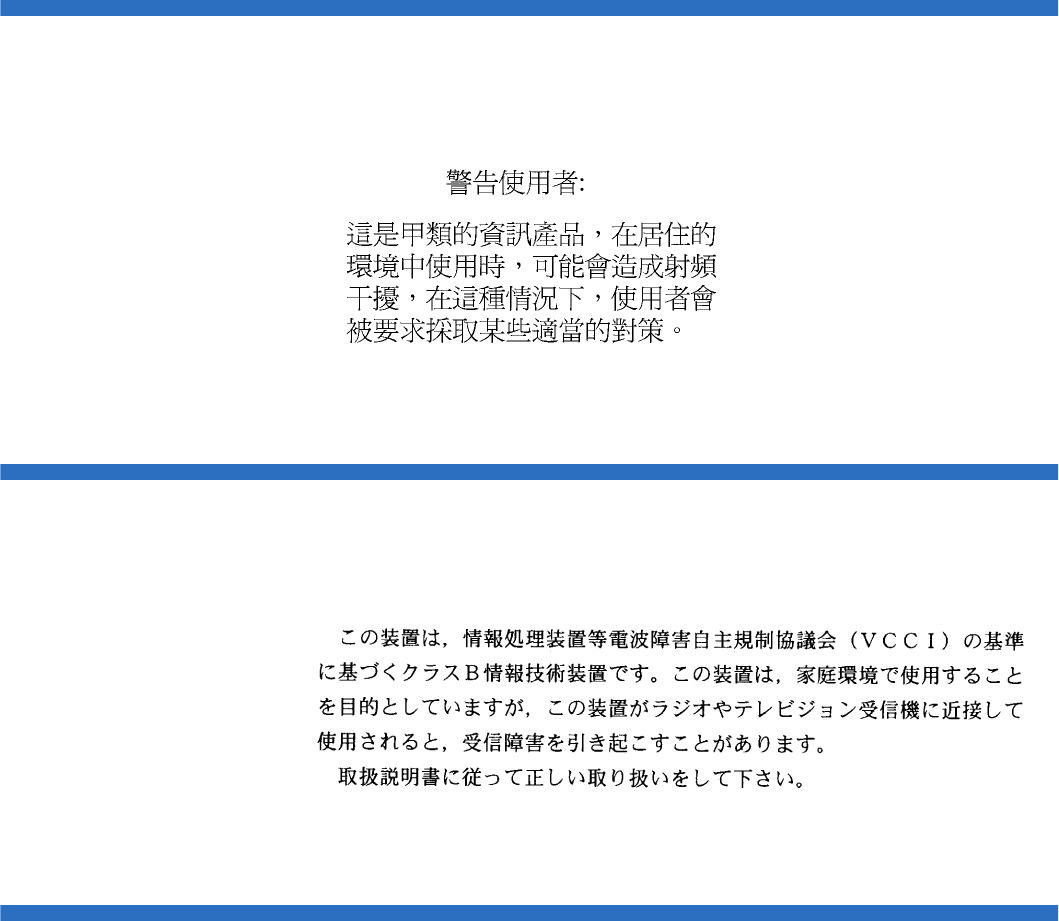
Taiwan Statement
Quantum SuperLoader 3 User’s Guide 171
Taiwan Statement
Japan Notice
Canadian Notice (Avis Canadien)
This Class A digital apparatus complies with Canadian ICES-003.
Cet appareil numérique de la classe A est conforme à la norme Canadian
Notice (Avis Canadien)

European Union Notice
Quantum SuperLoader 3 User’s Guide 172
This Class A digital apparatus meets all requirements of the Canadian
Interference-Causing Equipment Regulations.
Cet appareil numérique de la classe A respecte toutes les exigences du
Règlement sur le matériel brouilleur du Canada.
European Union Notice
Products with the CE Marking comply with both the EMC Directive (89/
336/EEC) and the Low Voltage Directive (73/23/EEC) and its
amendment (93/68/EECD) issued by the Commission of the European
Community.
Compliance with these directives implies conformity to the following
European Norms (in brackets are the equivalent international standards):
• EN55022 (CISPR 22) - Electromagnetic Interference
• EN50082-1 (IEC801-2, IEC801-3, IEC801-4) - Electromagnetic
Immunity
• EN60950 (IEC950) - Product Safety
Product Safety Electrostatic Discharge
To prevent damaging the system, be aware of the precautions you need
to follow when setting up the system or handling parts. A discharge of
static electricity from a finger or other conductor may damage system
boards or other static-sensitive devices. This type of damage may reduce
the life expectancy of the device.
To prevent electrostatic damage, observe the following precautions:
• Avoid hand contact by transporting and storing products in static-
safe containers.
• Keep electrostatic-sensitive parts in their containers until they arrive
at static-free workstations.

Grounding Methods
Quantum SuperLoader 3 User’s Guide 173
• Place parts on a grounded surface before removing them from their
containers.
• Avoid touching pins, leads, or circuitry.
• Always be properly grounded when touching a static-sensitive
component or assembly.
Grounding Methods
There are several methods for grounding. Use one or more of the
following methods when handling or installing electrostatic-sensitive
parts:
Use a wrist strap connected by a ground cable to a grounded workstation
or computer chassis. Wrist straps are flexible straps with a minimum of
1 mega-ohm 10 percent resistance in the ground cords. To provide proper
ground, wear the strap snug against the skin.
Use heel straps, toe straps, or boot straps at standing workstations. Wear
the straps on both feet when standing on conductive floors or dissipating
floor mats.
Use conductive field service tools.
Environmental Compliance
Quantum is committed to providing quality products in an
environmentally sound manner and to comply with all applicable
environmental laws, rules and regulations.
This product was designed, manufactured and made available with
consideration to worldwide laws, rules and regulations applicable to the
product and the electronics industry including the European Union
Directives 2002/95/EC & 2002/96/EC (RoHS and WEEE).

Disposal of Electrical and Electronic Equipment
Quantum SuperLoader 3 User’s Guide 174
For further information on Quantum’s Environmental Compliance and
Global Citizenship, please consult the following Web site at
http://qcare.quantum.com.
Disposal of Electrical and Electronic Equipment
This symbol on the product or on its packaging
indicates that this product should not be disposed of
with your other waste. Instead, it should be handed
over to a designated collection point for the recycling of
electrical and electronic equipment. The separate
collection and recycling of your waste equipment at the
time of disposal will help to conserve natural resources
and ensure that it is recycled in a manner that protects
human health and the environment. For more information about where
you can drop off your waste equipment for recycling, please visit the
Quantum Web site at http://qcare.quantum.com or contact your local
government authority, your household waste disposal service or the
business from which you purchased the product.

SuperLoader 3 Autoloader User’s Guide 175
Glossary
Aaccess Read, write, or update information on a storage
medium, such as tape.
access time The interval between the time a request for data is
made by the system and the time the data is available
from the drive.
allocation The process of assigning particular areas of the media
to particular data or instructions.
archiving The removal of data from the computer system on to
secondary storage media that is safely stored away.
autoloader A robot that includes one tape drive and one or more
magazines of tape cartridges. Autoloaders are used for
unattended data backup.
Bbackup A copy of a file, directory, or volume on a separate
storage device from the original, for the purpose of
retrieval in case the original is accidentally erased,
damaged, or destroyed.
backward compatibility The ability of a current drive product to
read tapes written on earlier model drives.
base plate An aluminum die casting that acts as the support
platform for the other modules and for the drive

Glossary
SuperLoader 3 Autoloader User’s Guide 176
enclosure. The base plate is standard 5.25 inch (133.35 mm) full-
high form factor and includes the precision mounting holds used
to install Super DLTtape drives into a server or tape library. The
TCM acts as the prime base plate for the Super DLTtape system.
bus A communication pathway between components in a computer
system.
CC Celsius. A measurement of temperature where 0 degrees is the
freezing and 100 degrees is the boiling point of water.
cartridge receiver At tape insertion, the cartridge receiver assembly is
responsible for guiding the tape into its operating position,
opening its door, unlocking the cartridge brakes, and securing
the tape for operation. At tape ejection, the cartridge receiver
assembly reverses the process and automatically ejects the tape a
fixed distance from the front of the drive.
compressed capacity Capacity after data has been processed to reduce
storage space while maintaining data integrity using either
software or hardware.
cartridge tape module (CPTM) The Super DLTtape CTM contains the
AMP media feature of Quantum’s LGMR technology. The main
function of the CTM is to provide the magnetic recording media
used by the drive to store customer information. The CTM also
provides the protective cartridge that allows the media to be
removed and stored safely.
Ddata compression A process that reduces the amount of storage space
required to hold a particular block of data. Data transfer speed
and total tape capacity are affected by the data compression
achieved. In accordance with industry practice, a typical
compression ratio is 2:1 of data storage. Actual compression
ratios achieved are dependent on the redundancy of data files
being recorded.
data control module (DCM) The DCM contains several of the functions
and features of Quantum’s LGMR technology, which is at the
heart of the Super DLTtape technology. Of the five technologies
that constitute the LGMR technology, two are found in the DCM.
These are the POS and the MRC heads. The main functions of the
DCM are to provide the path and guides for all tape motion
inside the drive and to write data to and read data from the tape.

Glossary
SuperLoader 3 Autoloader User’s Guide 177
device According to SCSI specification, up to eight SCSI devices can be
connected to a single SCSI bus. Each SCSI device contains a SCSI
ID number that can be set to 0 through 7.
device driver A low-level (usually kernel-mode) operating system
component that enables a PC to communicate with peripheral
devices such as fixed disk drives, CD-ROMs, and tape drives.
Each kind of device requires a different driver. Device driver
programs are loaded into memory at boot time.
DHCP Dynamic Host Configuration Protocol. Software that
automatically assigns IP addresses to client stations logging onto
a TCP/IP network.
differential A term referring to the electrical characteristics of the signal
used on the SCSI bus interface. Differential signals minimize the
effect of common mode signal noise and allow the SCSI bus to
operate reliably over greater distances at a higher speed.
domain A group of computers, programs, and devices on a network
administered as a unit with common procedures and rules for
use by a specific group of users. A user logs on to the domain to
gain access to the resources.
driver A software program allowing the operating system to control a
device such as a library, printer, or video card. Many devices do
not respond properly if the correct driver is not installed in the
computer.
EECC Error Correction Code, also known as Error Checking and
Correction. The incorporation of extra parity bits in transmitted
data in order to detect errors that can be corrected by the
controller.
EDC Error Detection Code. DLT tape drives include a 16-bit EDC with
every 4 KB of user data. The EDC helps the drive detect and
recover any errors that may occur.
EEPROM Electronically-Erasable Programmable Read Only Memory. An
integrated circuit memory chip that can store programs and data
in a non-volatile state. These devices, which are used to store
firmware in DLT tape drives, can be erased and reprogrammed
with new data.
EMI Electromagnetic Interference. Electrical interference caused by
electromagnetic radiation.

Glossary
SuperLoader 3 Autoloader User’s Guide 178
encoding The protocol by which particular data patterns are changed
prior to being written on the tape surface as a pattern of On and
Off or 1 and 0 signals.
erase The removal of data from a piece of media.
error A message that occurs when there is a loss of ability to interpret
recorded data. Usually due to magnetic issues or defects in or on
the media.
Error Correction Code See ECC.
Error Detection Code See EDC.
Ethernet a local-area network (LAN) protocol using high-speed
communications at 10 megabits per second.
external drive A drive mounted in an enclosure, separate from the
computer system enclosure, with its own power supply and fan,
and connected to the system by a cable.
FF Fahrenheit. A temperature measurement system where 32
degrees is the freezing point and 212 degrees is the boiling point
of water.
FCC Federal Communications Commission. A United States agency
responsible for enforcing communications related regulations
stating how much radiation computers and other electronic
equipment are allowed to emit.
Fibre Channel A Gigabit-speed network technology used for storage
networking. Fibre Channel is standardized in the T11 Technical
Committee of the International Committee for Information
Technology Standards (INCITS). It has become the standard
connection type for storage area networks in enterprise storage.
Fibre Channel signaling is typically run on fiber optic cables.
Fibre Channel protocol (FCP) is the interface protocol of SCSI on
the Fibre Channel.
files A distinct group of data blocks.
file-by-file backup A recording method that records data a single file at a
time as opposed to mirroring a tape or block of data.
firmware Permanent or semi-permanent instructions and data
programmed directly into the circuitry of programmable read-
only memory or electronically-erasable programmable read-only
memory chips. Used for controlling the operation of the

Glossary
SuperLoader 3 Autoloader User’s Guide 179
computer or tape drive. Distinct from software, which is stored in
random access memory and can be altered with ease.
format A magnetic track pattern that specifies the locations of the tracks
and sectors. This information must exist on a tape before it can
store any user data. Formatting erases any previously stored
data.
formatted capacity The amount of room left to store data on a tape after
writing the sector headers, boundary definitions, and timing
information during a format operation.
Form Factor 1 The industry standard that defines the physical, external
dimensions of a particular device.
Form Factor 2 The general geometric dimensions of a drive or width of a
piece of tape media.
FTP File Transfer Protocol. A protocol used to transfer files over a
TCP/IP network.
full height Dimensions of a drive that meet standard height
requirements, usually 3.25 inches (82.55 mm) for a tape or disk
drive product.
GGB Gigabyte. A unit of measurement equal to 1 million kilobytes.
GHz Gigahertz. A measurement of frequency that equals one
thousand million Hz, or one thousand MHz. Speeds for
computer microprocessors, buses, and interfaces are often
measured in GHz.
Hhalf height Standard drive size equivalent to half the vertical space of a
5.25 inch (133.35 mm) drive.
hard drive A drive that reads and writes data on a hard disk. The terms
hard drive and hard disk are often used interchangeably.
hard error A data error that persists when the tape is reread, usually
caused by defects in the physical surface.
head The tiny electromagnetic coil and metal pole used to create and
read back the magnetic patters on the tape. Also known as the
read/write head.
head life The length of time a tape drive head will function without
replacement or repair, usually measured in hours of use.

Glossary
SuperLoader 3 Autoloader User’s Guide 180
Hierarchical Storage Management (HSM) A method of storing massive
amounts of data in tape libraries that allows for easy and rapid
recall of the material. Due to the lowering cost of disk drives,
HSM has yet to reach its full potential.
HTTP Hypertext Transfer Protocol. A protocol for exchanging files
between computers connected to the Internet.
Hz Hertz. A unit of frequency measurement that equals 1 cycle per
second. Computers and electronic devices are often measured in
kilohertz (kHz), megahertz (MHz), gigahertz (GHz), or terahertz
(THz).
IISV Independent Software Vendor.
image backup A backup option that takes a “snapshot” of an entire
system by writing a volume image to tape sector-by-sector, rather
than file-by-file. This method of backup is very fast and allows
companies to backup critical information in a limited backup
window.
interface A hardware or software protocol, contained in the electronics
of the tape controller and tape drive that managed the exchange
of data between the drive and computer. The most common
interfaces for small computer systems are AT (IDE) and SCSI.
internal drive A drive mounted inside one of a computer’s drive bays.
Internet A worldwide network of computer servers originally developed
by the federal government as a communication system in the
event of nuclear war or other wide-scale disaster.
intranet A private version of the Internet that provides a cost-effective
way to publish critical information and provide an interactive
communication path for heterogeneous systems.
IP Internet Protocol. A communications protocol which contains a
network address and routes a message to a different network.
Jjumper A tiny connector box that slips over two pins that protrude from
a circuit board. The jumper can be moved to change electrical
connectors. When in place, the jumper connects the pins
electrically. Some board manufacturers use dual in-line package
(DIP) switches instead of jumpers.

Glossary
SuperLoader 3 Autoloader User’s Guide 181
KKB Kilobyte. A unit of measure consisting of 1,024 bytes.
kHz Kilohertz. A measurement of frequency that equals 1000 Hz.
LLAN Local Area Network. A computer network covering a relatively
small area. A LAN usually is confined to a building or a few
nearby buildings. A LAN can be connected to another LAN over
any distance through telephone lines and radio waves to form a
wide area network (WAN).
LCD Liquid Crystal Display. The technology used by portable
computer and flat-panel displays. The Operator Control Panel on
the front of the SuperLoader is an LCD screen.
Lempel-Ziv Algorithm A data compression technique used in all DLT
tape drives. Named after Abraham Lempel and Jacob Ziv.
library system A system that uses a robotic mechanism to automatically
load and unload tape cartridges into one or more tape drives.
Distinguishable from stackers and autoloaders in their ability to
provide random access to tape cartridges. The DLTstor is a tape
library system offered by Quantum Corporation.
linear recording Recording technology in which data is written in tracks
that run the length of the tape media. Contrast with helical scan
technology which records data diagonally across the tape.
MMB Megabyte. A unit of measurement equal to 1 million bytes.
MCBF Mean Cycles Between Failures. This is average cycle count
between possible failures. A cycle is the movement of a cartridge
from the tape drive to a magazine slot and the selection of
another cartridge and moving that cartridge back to the drive.
MHz MegaHertz. A measurement of frequency in millions of cycles
per second.
MTBF Mean Time Between Failures. Reliability rating indicating the
expected failure rate of a product in power on hours (POH). Since
manufacturers differ in the ways they determine the MTBF,
comparisons of products should always take into account the
MTBF calculation method.
MTTR Mean Time to Repair. The average time it takes to repair a drive
that has failed for some reason. This only takes into consideration
the changing of the major subassemblies such as the printed

Glossary
SuperLoader 3 Autoloader User’s Guide 182
circuit board or sealed housing. Component-level repair is not
included in this number as this type of repair cannot be
performed in the field.
media The material or device used to store information in a storage
subsystem, such as a tape or disk drive. DLTtape media is a high-
grade metal particle (MP) formulation that takes advantage of the
latest advances in binder chemistry. By combining both solid and
liquid lubricants in the tape binder system, tape and head wear
are reduced while repelling airborne particles that could affect
read/write head performance. In addition, by using a uniform
particle shape, a dense binding system, a smooth coating surface,
and a specially selected base file, Quantum DLTtape half-inch
cartridge tapes take advantage of shorter wavelength recording
schemes to ensure read compatibility with future generations of
DLT drives.
Metal Particle (MP) tape A magnetic recording media in which a flexible
base is coated with a mixture of magnetic particles and a bonding
agent. See also media.
microprocessor The integrated circuit chip that performs the bulk of
data processing and controls the operation of all of the parts of
the system.
microsecond (μs) One millionth of a second (.000001 sec.).
millisecond (ms) One thousandth of a second (.001 sec.).
minicomputer A somewhat out-of-date term used to describe a class of
multi-user computer that was one notch below a mainframe
system. Minicomputer popularity fell with the rise in popularity
of the networked PC. Today’s server systems perform many of
the functions that were once the domain of minicomputers.
Mission Critical Applications that are vital to a company or
organization’s well-being.
Nnative mode Refers to the uncompressed storage capacity of a tape or
disk subsystem. for instance, a DLT 7000 tape drive can store 35
GB in native mode and 70 GB with 2:1 compression.
near-on-line storage An application that uses a tape drive or tape
automation system in much the same way as a hard disk drive.
Provides easy access to large amounts of critical information.

Glossary
SuperLoader 3 Autoloader User’s Guide 183
Ooverhead Command overhead refers to the processing time required by
the controller, host adapter, or drive prior to the execution of a
command. Lower command overhead yields higher drive
performance.
overwrite To write data on top of existing data thus erasing the original
data.
OEM Original Equipment Manufacturer.
Pparallel channel architecture Allows DLT tape drives to read/write
multiple channels simultaneously providing an industry-leading
data transfer rate in the DLT 7000 drive. with this architecture,
data blocks are not required to be located on any particular track
or in consecutive order. This channel-independent block
structure provides a powerful write-error handling system that
allows bad blocks to be rewritten on the next available command.
Partial Response, Maximum Likelihood PRML. A technology that allows
a disk or tape drive’s read channel to pack more data in the same
amount of space on magnetic media.
peak transfer rate The maximum speed with which information moves
inside a tape drive or between drive and host. Usually measured
in megabytes per second.
performance A measure of the speed of the drive during normal
operation. Factors affecting performance are seek times, transfer
rate, and command overhead.
peripheral A device added to a system as a complement to the basic
central processing unit (CPU), such as a disk drive, tape drive, or
printer.
POH Power-on Hours. The unit of measurement for mean time
between failure (MTBF), expressed as the number of hours that
the drive is powered on. See MTBF.
POST Power-on Self Test. Diagnostics programs, loaded automatically
by the BIOS, that perform basic tests on the major system
components, such as memory, cartridge and magazine
information. If no problems are detected during POST, the
system continues the start-up process.
PRML See Partial Response, Maximum Likelihood.

Glossary
SuperLoader 3 Autoloader User’s Guide 184
QQIC Quarter Inch Cartridge. A tape storage subsystem that uses
0.25 inch (6.35 mm) wide media.
RRAM Random Access Memory. an integrated circuit memory chip that
allows information to be stored and retrieved by a
microprocessor or controller. The information can be stored or
accessed in any order, and all storage locations are equally
accessible.
RAIT Redundant Array of Independent Tape Drives
random access The ability to directly locate any piece of data without
having to read everything in memory or on disk.
read after write A mode of operation that has the computer read back
each data block immediately after it is written on the tape,
checking that the data read back is the same as recorded.
read/write head The mechanism by which data is recorded onto magnetic
media in a tape drive system. See read after write.
Reed-Solomon error correction An error correction technique based on
research done by Irving reed and Gustave Solomon at MIT’s
lincoln Laboratory in the 1960s. First used to check the accuracy
of data received from the Voyager spacecraft.
restore To replace data on the hard drive from another media source.
ROM Read Only Memory. Integrated circuit chip containing programs
and data that can be accessed and read but cannot be modified.
SSCSI Small Computer System Interface. An American National
Standards Institute (ANSI) interface between the computer and
peripheral controllers. Apple MacIntosh systems and many
UNIX operating system workstations use the SCSI interface.
scalability Refers to the capability provided by the DLT tape drive
family to read tapes from previous generations of drives. Allows
users to upgrade to a faster, higher capacity DLT drive, yet still
be able to read tape recorded on an older system. The term also
refers to the ability of DLT tape library systems to be upgraded
with a higher performance DLT drive and thus provide more
capacity and performance in the same footprint. See backward
compatibility.
seek The movement of a read/write head to a specific data track.
Glossary
SuperLoader 3 Autoloader User’s Guide 185
self cleaning head Found in all DLT tape drives. Tiny ridges on either
side of the DLT drive read/write head continuously wipe the
tape clean as it passes over the head. This is why there is no
periodic cleaning prescribed for DLT tape drives.
server A powerful computer system with a large hard disk drive that
serves the information access and communication needs of
multiple users. Often servers are dedicated to a particular
function such as Internet access, printing, file management,
backup, and network communications.
servo data Magnetic markings written on the media that guide the read/
write heads to the proper position.
shelf life The length of time that a tape can be stored without losing its
magnetic strength. For DLTtape media, this period is 30 years or
more.
shock rating A rating, expressed in Gs which stands for multiples of
gravity, of how much shock a tape drive can sustain without
damage. Operating and non-operating shock levels are usually
specified separately.
SMTP Simple Mail Transfer Protocol. An e-mail protocol on the Internet
that defines the message format and the message transfer agent.
SNMP simple Network Management Protocol. A protocol that monitors
and controls a network.
SNTP Simple Network Time Protocol. SNTP is based on NTP, the
Network Time Protocol, an industry standard way for computers
to synchronize their time to an external reference standard. NTP
and SNTP are fully interoperable. Each consists of a client, for
example the SuperLoader, which obtains the current time (in
UTC) from either an SNTP server or an NTP one. SNTP and NTP
are in wide use on the Internet. NTP is specified by RFC1305.
SNTP is specified by RFC2030.
soft error A faulty data reading that does not recur if the same data is
reread from the disk or corrected by ECC. Usually caused by
power fluctuations or noise spikes.
stacker A tape automation system that sequentially loads and unloads
tape cartridges. does not provide random access to cartridges of
the data stored on them.
stepper A type of motor that moves in discrete amounts with each
electrical pulse.

Glossary
SuperLoader 3 Autoloader User’s Guide 186
supply reel The reel of tape contained within the DLTtape cartridge.
DLTtape IV, for example, contains 1,800 feet (548.64 m) of tape.
surface The side of the tape that is coated with the magnetic material for
recording data.
sustained transfer rate The data transfer rate of a tape drive in native
mode. for example, the DLT 7000 has a sustained transfer rate of
5 MB in native mode, and up to 10 MB at 2:1 compression.
system manufacturers Makers of computer systems and tape library
systems.
Symmetric Phase Recording (SPR) A recording technique introduced
with the DLT 7000 that writes data at alternating angles in a
herringbone pattern thereby eliminating the need for guard
bands between data tracks, and providing higher data density.
TTPI Tracks per Inch. A DLT 7000 tape drive, for example, writes data
a density of 416 tpi, or 208 tracks across the width of the half-inch
DLTtape media.
take-up reel The reel inside every DLT tape drive onto which DLTtape
media is wound. The in-the-drive take-up reel enables DLT tape
systems to operate using a single-reel cartridge and thereby pack
more tape and data into every cartridge.
tape path The path through which tape moves from the cartridge, past
the read/write head, and onto the take-up reel. The patented
DLT drive head guide assembly provides a gentle and solid path
that ensures tracking accuracy and long tape life.
tar A UNIX operating system command that stands for “create tape
archives” and/or extract files.
TCP/IP Transmission Control Protocol/Internet Protocol. A
communications protocol which ensures that the total amount of
bytes sent is received correctly, and also provides the routing
information.
thin film A type of coating allowing very thin layers of magnetic material
used on tape drive read/write heads. Media with thin film
surfaces can store greater amounts of data.
track A linear or angled pattern of data written on a tape surface. DLT
tape drives write information on multiple tracks simultaneously.
track-to-track seek time The time required for the read/write heads to
move to an adjacent track.

Glossary
SuperLoader 3 Autoloader User’s Guide 187
transfer rate The rate at which the drive sends and receives data from the
controller. Usually measured in megabytes per second. A
DLT 7000 drive, for example, has a native transfer rate of 5 MB/s.
Uunformatted capacity The total number of usable bytes on the media,
including the space that will be required later to record location,
boundary definitions, and timing information. See also formatted
capacity.
Vvolume The quantity of information written on a piece of media.
Typically measured in megabytes or gigabytes.
WWrite Once, Read Many (WORM) An optical disk technology that allows
the drive to store and read back data but prevents the drive from
erasing information once it has been written.
write-protected Files or media that cannot be changed. user write-
protection when you want to protect data from being changed or
destroyed. To write-protect most tape cartridges, slide the write-
protect tab to the “locked” position.
ZZIF Zero Insertion Force. A type of socket or connector allowing a
computer chip or bar code reader to be inserted or removed with
no stress applied to either the chip or bar code reader and its
respective socket.

Quantum SuperLoader 3 User’s Guide 188
Index
A
A500 Hard Read Error 152
A501 SDLT Hard Write Error 155
A502 SDLT Loader Communication
Error 157
A503 SDLT Drive Servo Error 158
A507/A508 Directory Read Failure/
Directory Write Failure 163
Auto Clean
On-board Remote Management
54
autoloader
environmental specifications 129
packing for shipment 123
performance specifications 126
power specifications 130
preparing for shipment 122
removing from rack 122
returning for service 122
shock specifications 131
status, front panel 42
unpacking 13
vibration specifications 130
autoloader logs 107
B
back panel
overview 17
bar code reader 26
Bugcheck Error logs 150
C
Canadian Notice (Avis Canadien)
171
cartridges
ejecting single 33
inserting single 31
moving single 33
using 30
Change mode
setting, front panel 76
choosing a location 10
cleaning tape
On-board Remote Management
53
Client Authorization Control 58
Client Overlap Control 59
compression 46
On-board Remote Management
53
Configuration Page
system operations 50
contact Quantum xvi
criteria
location 10
customer support
before contacting 102
D
data compression 46
device drivers
installing 24
diagnostics
entering password 86
front panel 86

Index
189 Quantum SuperLoader 3 User’s Guide
On-board Remote Management
62, 63, 87
performing 85
POST 82
tests 84
E
ejecting
magazines 36
single cartridge 33
electrostatic discharge (ESD) 172
error or history logs
On-board Remote Management
62
ESD 172
Ethernet
setting, front panel 72
European Union Notice 172
Event Error logs
A500 Hard Read Error 152
A501 SDLT Hard Write Error 155
A502 SDLT Loader
Communication Error 157
A503 SDLT Drive Servo Error
158
A507/A508 Directory Read
Failure/Directory Write
Failure 163
general information 152
F
FCC Statement 170
features
understanding 15
Fibre Channel
loop configuration 3, 5
firmware version
viewing, front panel 42
front panel
Change mode 76
controls 16
default passwords 67
diagnostic tests 86
diagnostics 84
element status 43
entering passwords 29
Ethernet 72
Ethernet information 45
IP address 72
IP gateway 74
logout 30
magazines 79
passwords 79
Random mode 76
SCSI ID 70
security options 78
Seq Cycle mode 76
Sequential mode 76
Sequential mode operations 77
SNTP server 74
stop diagnostic test 85
Subnet Mask 73
tape drive status 44
tape drive version 44
time 74
time server 74
viewing status 41
function keys
operators panel 27
G
grounding methods 173
H
Hard Error log
On-board Remote Management
108
I
identification
On-board Remote Management
63
inserting
single cartridge 31
installation
magazines 37
inventory
On-board Remote Management
64
running 46
IP address
setting, front panel 72
IP gateway
setting, front panel 74
J
Japan Notice 171

Index
Quantum SuperLoader 3 User’s Guide 190
L
Library Operations Page
On-board Remote Management
64
location
choosing 10
criteria 10
logout
front panel 30
logs
autoloader 107
Bugcheck Error logs 150
error or history, viewing 62
POST Failure 121
SCSI Check Condition Error logs
147
Soft logs 107
Tape Drive Error logs 146
lost passwords 80
LVD
Ultra320 interface 5
M
magazine blanks
using 35
magazines
ejecting 36
installation 37
On-board Remote Management
54
operating manually 38
setting, front panel 79
using 35
mode
On-board Remote Management
52
moving
single cartridge 33
N
network options
On-board Remote Management
56
O
On-board Remote Management
Auto Clean 54
cleaning tape 53
compression 53
diagnostics 62, 63, 87
error or history logs 62
identification 63
inventory 64
Library Operations Page 64
magazines 54
mode 52
network options 56
opening 48
overview 47
Random mode 52
SCSI ID 50
security options 57
Sequential Cycle mode 53
Sequential mode 52
Sequential Operations mode 65
Set to Home 64
status information 49
system reset 63
system time 55
time display 49
Updates Page 61
operators panel
entering passwords 29
function keys 27
functionality 27
overview
On-board Remote Management
47
SuperLoader 3 DLT-S4 5
SuperLoader 3 DLT-V4 4
SuperLoader 3 LTO-2 3
SuperLoader 3 LTO-3 3
SuperLoader 3 LTO-4 4
SuperLoader 3 SDLT 600 5
SuperLoader 3 VS160 4
P
passwords
default, front panel 67
default, On-board Remote
Management 49
entering on front panel 29
lost 80
setting, front panel 79
POST (Power-on Self Test) 82
POST Failure logs 121
power cables
connecting 18
Power-on Self Test (POST)
interpreting results 83
performing 83
preparation
host 23

Index
191 Quantum SuperLoader 3 User’s Guide
R
rackmounting 93
Random mode
On-board Remote Management
52
setting, front panel 76
regulatory
Canadian Notice (Avis
Canadien) 171
European Union Notice 172
FCC Statement 170
grounding methods 173
Japan Notice 171
Taiwan Statement 171
requirements
UL 11
S
safety
grounding methods 173
SCSI
connecting 18
SCSI bus requirements
general information 12
LTO-2 12
SDLT 600 12
VS160 12
SCSI Check Condition Error logs
147
SCSI ID
setting, front panel 70
setting, On-board Remote
Management 50
security options
On-board Remote Management
57
setting, front panel 78
Seq Cycle mode
setting, front panel 76
Sequential Cycle mode
On-board Remote Management
53
Sequential mode
On-board Remote Management
52
setting, front panel 76
Sequential mode operations
front panel 77
Sequential Operations mode
On-board Remote Management
65
Set to Home
On-board Remote Management
64
SNTP server
setting, front panel 74
Soft logs 107
specifications
autoloader environmental 129
autoloader performance 126
autoloader power 130
autoloader shock 131
autoloader vibration 130
DLT-S4 tape drive 144
DLT-V4 tape drive 140
LTO Ultrium 2 media 132, 134,
136
LTO-2 tape drive 132, 134, 136
SDLT 600 tape drive 142
SDLT II media 142, 144
VS1 media 138, 140
VS160 tape drive 138
status information
On-board Remote Management
49
viewing 41
Subnet Mask
setting, front panel 73
SuperLoader
rackmounting 93
System Operations
options 50
system reset
On-board Remote Management
63
system time
On-board Remote Management
55
T
Taiwan Statement 171
tape drive
DLT-S4 specifications 144
DLT-V4 specifications 140
LTO Ultrium 2 media
specifications 132, 134, 136
LTO-2 specifications 132, 134,
136
SDLT 600 specifications 142
SDLT II media specifications 142,
144
VS1 media specifications 138,
140
VS160 specifications 138
Tape Drive Error logs 146
time
setting, front panel 74
time display
On-board Remote Management
49

Index
Quantum SuperLoader 3 User’s Guide 192
time server
setting, front panel 74
troubleshooting
autoloader 106
Hard Log 108
POST 82
U
UL requirements 11
Updates Page
On-board Remote Management
61
V
viewing
element status, front panel 43
Ethernet information, front panel
45
firmware version 42
tape drive status, front panel 44
tape drive version, front panel 44
W
warranty
(see also www.quantum.com)
