Quantum5x Systems QT5000 QT-5000 Module User Manual
Quantum5x Systems Inc. QT-5000 Module
User Manual

QT-5000 Module
&
Remote Control Audio System
Rev: 6
Description
This document describes the use of the QT-5000 transmitter module and Remote Control Audio System
(RCAS).
History
Rev 1 Original
Rev 2 Updates
Rev 3 Added information about QT-5000 LED colours and blink patterns.
Rev 4 Update Software section
Rev 4.1 Added Technical detail for 802.15.4
Rev 5 Updated to Windows 7. Added any related changes.
Rev 6 Added Mounting Instructions

QT-5000 & Remote Control Audio System
Revision: 6
QT
-
5000 and RCAS User Manual v6.docx
Page
2
of
30
Q5X Systems, Inc. 2012
Table of Contents
Description .................................................................................................................................................... 1
History ........................................................................................................................................................... 1
Information to User ...................................................................................................................................... 3
Certification................................................................................................................................................... 3
Module Intergation into End Products ......................................................................................................... 3
Introduction .................................................................................................................................................. 4
Module mounting instruction ...................................................................................................................... 6
The QT-5000 Transmitter .............................................................................................................................. 9
Out-of-the-Box Setup ................................................................................................................................ 9
Using the Reset Key after Charge.............................................................................................................. 9
Charge LED Colour..................................................................................................................................... 9
Status LED ............................................................................................................................................... 10
Status LED Colour ................................................................................................................................ 10
Status LED Blink Patterns .................................................................................................................... 10
MicControl Software ................................................................................................................................... 11
Gateway Manager ................................................................................................................................... 11
Adding Gateways ................................................................................................................................ 11
Connecting to the Gateways ............................................................................................................... 13
Configuring the Gateway .................................................................................................................... 14
Session Setup .......................................................................................................................................... 16
Adding a Transmitter to the Session ................................................................................................... 16
Saving a Session .................................................................................................................................. 16
Opening a Session ............................................................................................................................... 16
Transmitter Panel .................................................................................................................................... 17
Tab 1 – Status and Control Tab ........................................................................................................... 18
Tab 2 – Configuration Tab ................................................................................................................... 20
Tab 3 – Miscellaneous Tab .................................................................................................................. 21
Customizing Group Names.................................................................................................................. 23
Troubleshooting ...................................................................................................................................... 24
Specifications ......................................................................................................................................... 26
Technical Data UHF Radio ................................................................................................................... 26
Technical Data 802.15.4 radio ............................................................................................................ 26
Technical Data QT-5000 Module .......................................................................................................... 26
Appendix - Installing the USB Driver ....................................................................................................... 27
QT-5000 & Remote Control Audio System
Revision: 6
QT
-
5000 and RCAS User Manual v6.docx
Page
3
of
30
Q5X Systems, Inc. 2012
FCC Notices:
Information to users:
This device complies with Part 15 of the FCC Rules. Operation is subject to the following two conditions:
(1.) This device may not cause harmful interference and (2.) This device must accept any interference
received, including interference that may cause undesired operation.
N
OTE
: This equipment has been tested and found to comply with the limits for a Class B digital device,
pursuant to part 15 of the FCC Rules. These limits are designed to provide reasonable protection against
harmful interference in a residential installation. This equipment generates, uses and can radiate radio
frequency energy and, if not installed and used in accordance with the instructions, may cause harmful
interference to radio communications. However, there is no guarantee that interference will not occur
in a particular installation. If this equipment does cause harmful interference to radio or television
reception, which can be determined by turning the equipment off and on, the user is encouraged to try
to correct the interference by one or more of the following measures:
— Reorient or relocate the receiving antenna.
— Increase the separation between the equipment and receiver.
— Connect the equipment into an outlet on a circuit different from that to which the receiver is
connected.
— Consult the dealer or an experienced radio/TV technician for help.
Warning: Changes or modifications not expressly approved by Quantum5X Systems Inc, could
void the user’s authority to operate the equipment.
Warning: This device has been designed to operate with the permanently attached wire
antennas to the PCB for the UHF and the 802.15.4 Radios, both having a maximum gain of 3
dBi. Replacing or modifying these antennas is strictly prohibited.
IMPORTANT
: Final product(s) after integration with this module shall be tested to comply with all
applicable FCC requirements and Unintentional radiators (FCC section 15.107 & 15.109) before declaring
compliance to Part 15 of the FCC Rules.
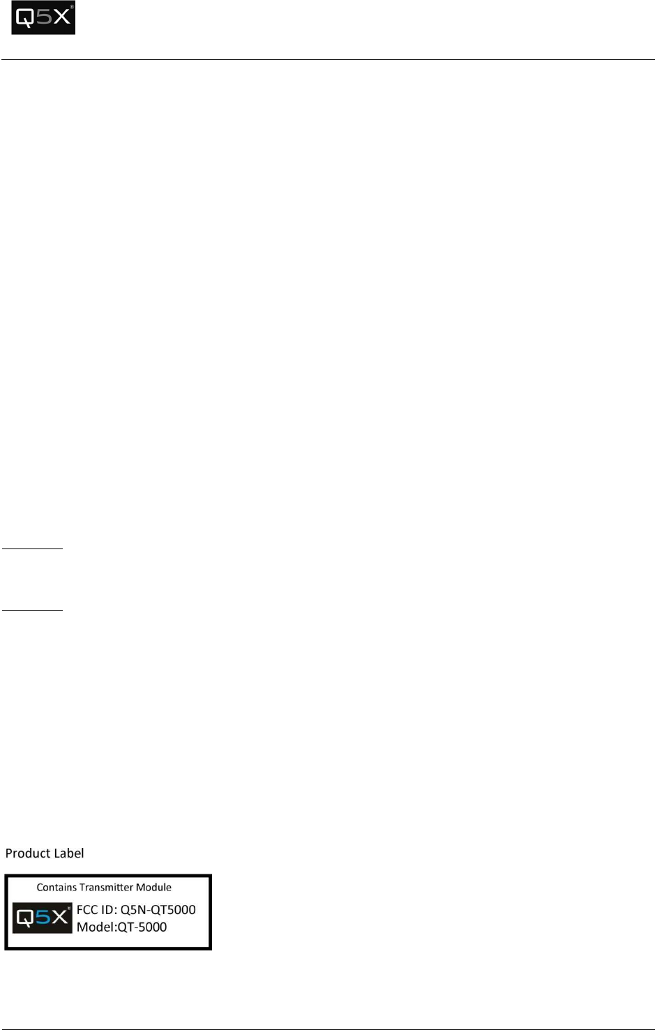
Labeling of the End Products:
Following permanent label shall be applied on all final procducts after module integration.
QT-5000 & Remote Control Audio System
Revision: 6
QT
-
5000 and RCAS User Manual v6.docx
Page
4
of
30
Q5X Systems, Inc. 2012
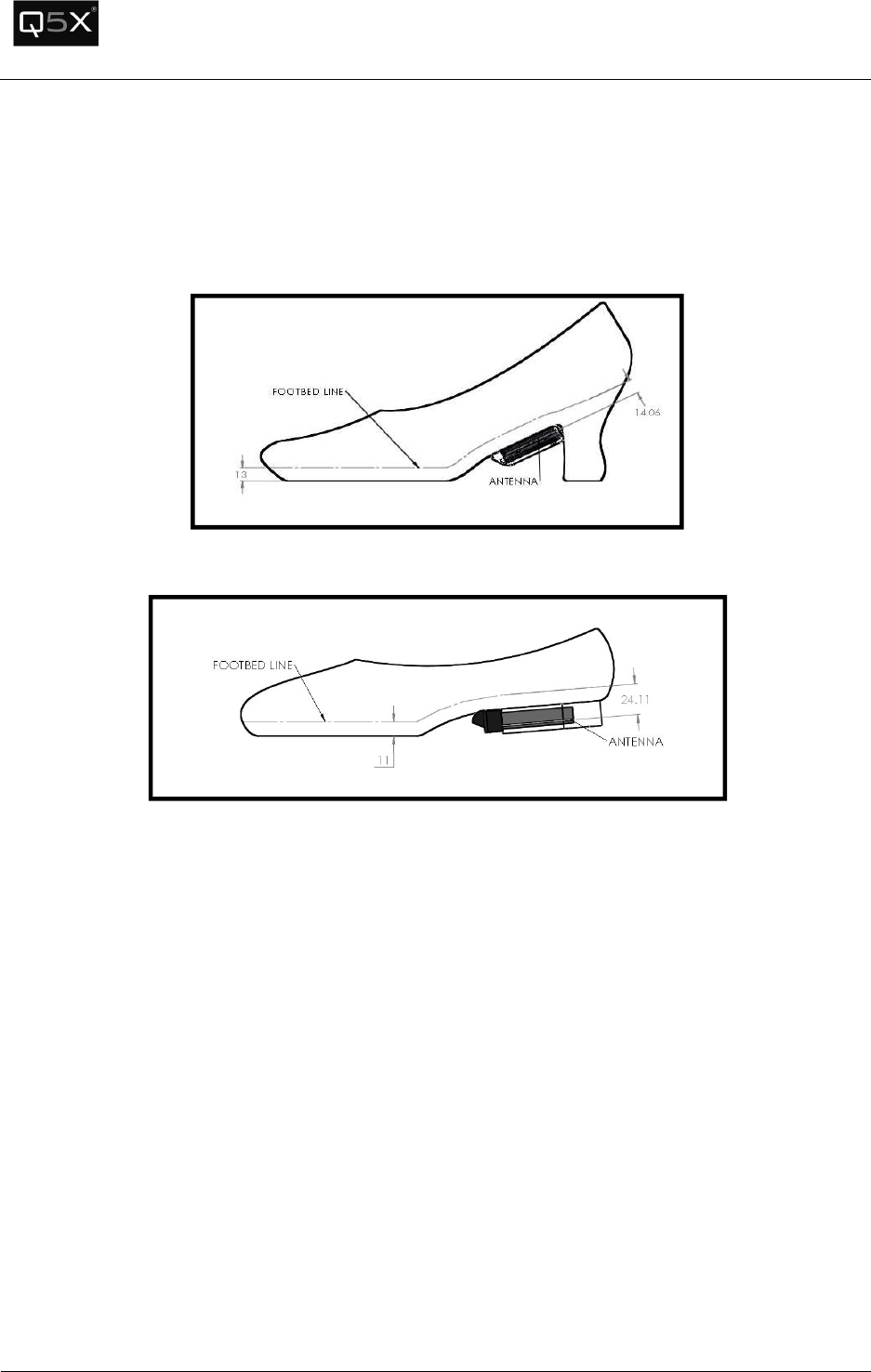
RF Exposure Compliance:
This module is a low-power device and complies with applicable RF exposure requirements as a mobile
device. For portable application, it is limited only to the specified host (tap shoe) configurations as
shown below as acceptable and approved with this filing.
Figure 1 -High Heel Antenna Spacing
Figure 2 - Low Heel Antenna Spacing
RF Exposure Warning:
The applicant hereby affirms that installation of this module will only be performed on shoe models that
have a minimum 10 mm separation distance from the outside surface/antenna of the module to the
closest surface of the foot.
The module integrator must:
1) Ensure that the QT-5000 module antenna is mounted in such a way that the minimum spacing
of 10 mm is maintained between the antenna and the wearer at all times.
2) Ensure that the minimum spacing between the wearer and the module antenna must be in free
space or non-metallic material.
QT-5000 & Remote Control Audio System
Revision: 6
QT
-
5000 and RCAS User Manual v6.docx
Page
5
of
30
Q5X Systems, Inc. 2012
The module integrator may not:
1) Alter, modify or remove the module case.
2) Make changes to the Circuit Card Assembly of the module.
3) Remove, change or alter the integrated UHF antenna or the 802.15.4 antenna.
Failure to comply with these restrictions will result in violation of the FCC certification.
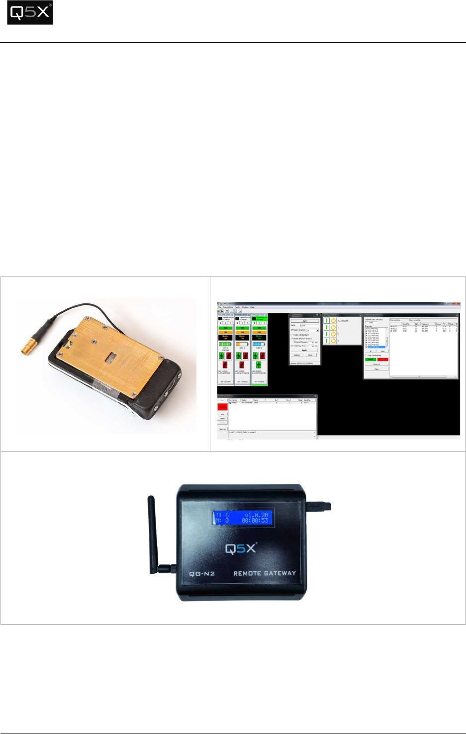
Introduction
The RCAS consists of the three main components:
QT-5000 Module
MicControl Software
Ethernet Gateway
QT-5000 & Remote Control Audio System
Revision: 6
QT
-
5000 and RCAS User Manual v6.docx
Page
6
of
30
Q5X Systems, Inc. 2012
Module Integration into Host End Products
The QT-5000 Module Transmitter has been designed by Quantum5X Systems Inc. to be used exclusively
by Quantum5X as a building block for their wireless audio transmitter products. The module, as
designed, is a standalone unit that is ready for integration into final form factor with the limitation for
portable use as specified in RF Exposure compliance. For proper usage of the module, the module
integrator must ensure that the input power and input audio signal do not exceed the specified limits as
outlined in the specification section. Failure to do so will result in damage to the module.
QT-5000ModuleMounting
Mounting of the QT-5000 module must provide a solid, reliable, mechanical connection between the
module and the tap shoe. If the QT-5000 module is not securely fastened to the tap shoe, it may
become separated from the shoe during dancing and could cause harm to the wearer, the audience
member or the module. Below are two sets of instruction for mounting to two different styles of
shoes: high heel and a low heel style of shoe. In each case, it is important to maintain the minimum
10 mm antenna spacing of the module from the wearer.
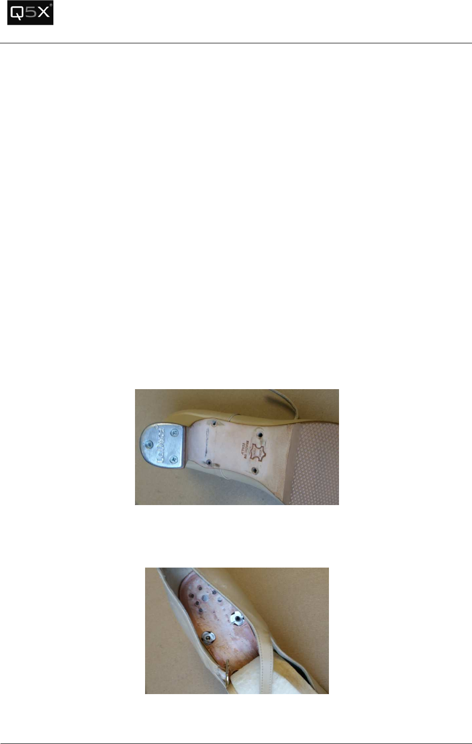
High Heel Tap Shoe
The tap shoe first needs to be modified to allow the QT-5000 module to be fastened to the shoe.
Figure 3 -
Mounting Holes Drilled into
Four holes are drilled into the sole of the shoe, and up through the foot bed.
Figure 4 -
T-Nuts installed into sole
QT-5000 & Remote Control Audio System
Revision: 6
QT
-
5000 and RCAS User Manual v6.docx
Page
7
of
30
Q5X Systems, Inc. 2012
The T-nuts provide a threaded insert for the transmitter pod to screw into. The insole is pulled back
from the foot bed and the T-nuts are flush mounted into the foot bed from the top side of the shoe.
Figure 5 - Transmitter Pod attached to Shoe
The transmitter pod is held in place by four #4 bolts that are screwed into the T-nuts, which are
mounted into the sole of the shoe. It is very important to ensure the correct length of the screws used
so that the screw does not protrude above the foot bed of the shoe.
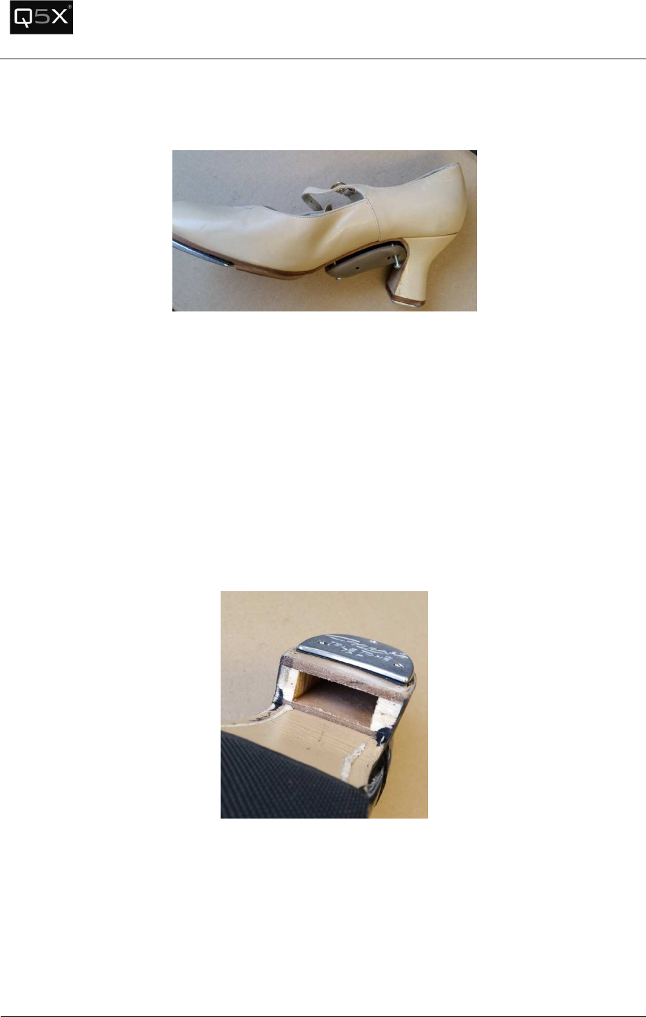
Low Heel Tap Shoe
In order to mount the transmitter module to the low heel tap shoe, the heel must first be modified. It is
recommended that the heel of the tap shoe be modified by a professional shoe maker to ensure the
modification is done in the correct manner.
Figure 6 - Heel Cavity
The heel of the tap shoe needs to be modified to allow for the transmitters module to slide into the
opening. The opening needs to be 58.4 mm X 36.75 mm X 15.3 mm.
QT-5000 & Remote Control Audio System
Revision: 6
QT
-
5000 and RCAS User Manual v6.docx
Page
8
of
30
Q5X Systems, Inc. 2012
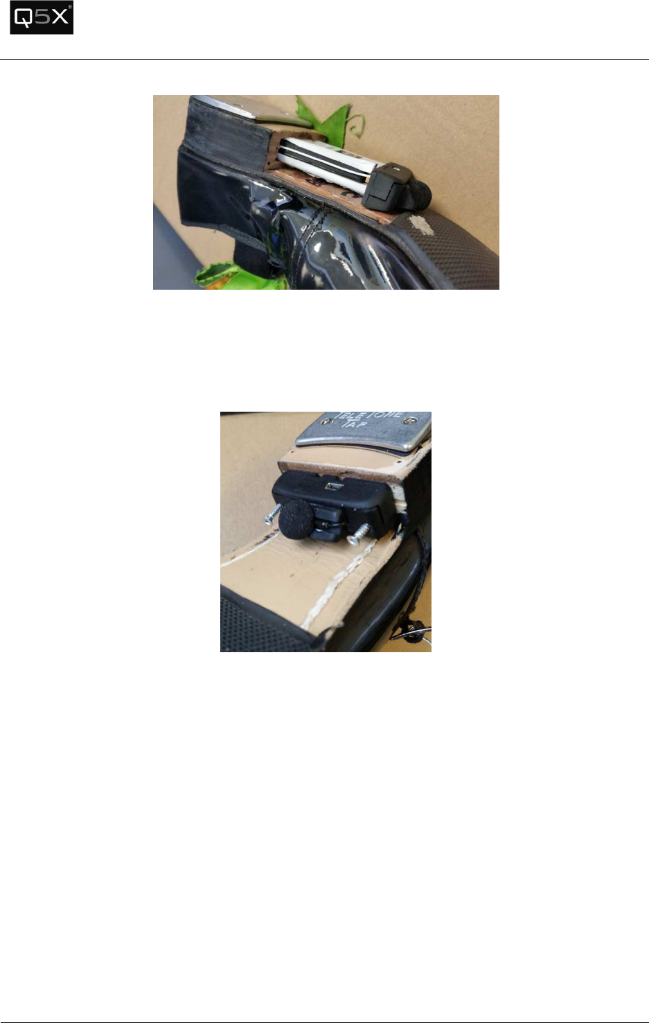
Figure 7 - Module inserted into Heel
The opening needs to large enough to allow the transmitter to slide into the opening without
friction. If the opening is too tight pressure can be transferred onto the transmitter during dancing
and could damage the module.
Figure 8 – Transmitter mounting
The QT-5000 module is then securely mounted to the transmitter with two 1” long #4 screws.
QT-5000 & Remote Control Audio System
Revision: 6
QT
-
5000 and RCAS User Manual v6.docx
Page
9
of
30
Q5X Systems, Inc. 2012
TheQT-5000Transmitter
Out-of-the-Box Setup
Ensure the QT-5000 is sufficiently charged by immediately inserting the charger.
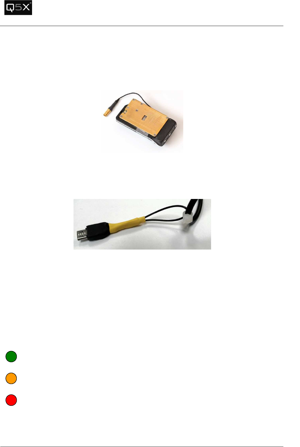
Using the Reset Key after Charge
Earlier hardware revisions of the QT-5000 had an issue where the unit would occasionally need to be
reset after being connected to a charger.
It is recommended that each time the charger is disconnected from the QT-5000, the Reset Key (which is
attached to the cable of the charger) should be inserted into the charge port, held for 1 second, and
then removed.
After the Reset Key is removed, the Status LED will blink green 3 times.
Charge LED Colour
When connected to a charger, the colour of the Charge LED will indicate the progress of the charging
cycle. The LED is located on the front of the transmitter.
Note: After the LED changes from Amber to Green, it is recommended it be charged for 15
more minutes while the trickle charge completes.
GREEN
–
The battery
is charged and ready for use.
AMBER
–
The battery level
low, but can be used for short term use, such as setup or quick
audio tests.
RED
–
The battery level is unusable and must be charged
.
QT-5000 & Remote Control Audio System
Revision: 6
QT
-
5000 and RCAS User Manual v6.docx
Page
10
of
30
Q5X Systems, Inc. 2012
Status LED
The Status LED indicates both the battery’s charge level and whether the transmitter is in ON mode
(transmitting audio) or in Standby mode (not transmitting audio).
Status LED Colour
The colour of the Status LED indicates the battery’s charge level.
Note: The meaning of the Status LED’s colour is slightly different than the Charge LED’s colour. See the
following:
.
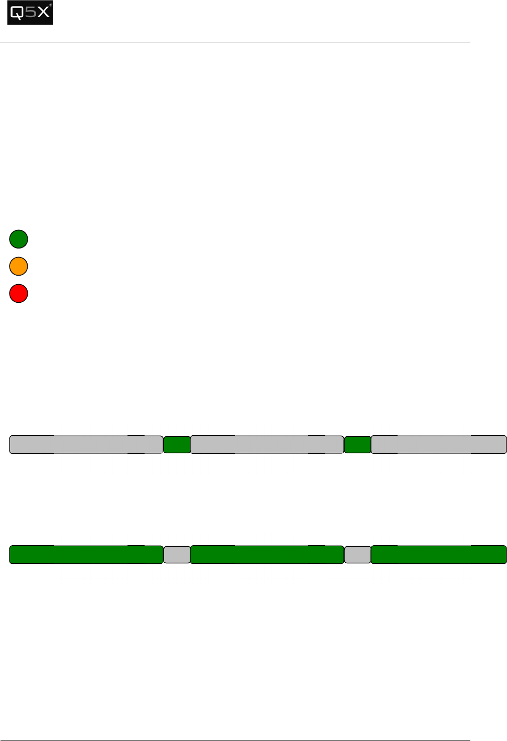
Status LED Blink Patterns
The blink pattern of the Status LED indicates the mode of the QT-5000.
STANDBY Mode (no audio) – The LED is off for 2.5 seconds and on for ¼ of a second, and repeats.
ON Mode (transmitting audio) – The LED is on for 2.5 seconds and off for ¼ of a second, and repeats.
GREEN
–
The battery level is over 50%
.
AMBER
–
The battery level is less than 50%.
RED
–
The battery level is unusable and must be charged
.
2.5 sec
¼ sec
O
ff
On
2.5 sec
¼ sec
O
ff
On
2.5 sec
O
ff
2.5 sec
¼ sec
On
Off
2.5 sec
¼ sec
On
Off
2.5 sec
On
QT-5000 & Remote Control Audio System
Revision: 6
QT
-
5000 and RCAS User Manual v6.docx
Page
11
of
30
Q5X Systems, Inc. 2012
MicControlSoftware
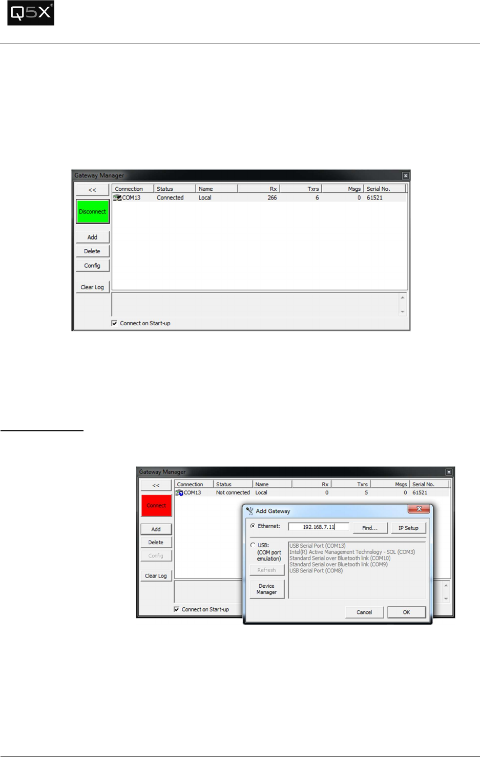
Gateway Manager
All Gateway management (adding, deleting, configuring) is performed from the Gateway Manager
window.
Adding Gateways
Note: To add or delete gateways, the software must be disconnected from all gateways.
1. Click Add, to add a gateway.
Network Gateway
If adding a Network
Gateway, select
“Ethernet” and enter the
gateway’s IP address.
Click “OK”.
QT-5000 & Remote Control Audio System
Revision: 6
QT
-
5000 and RCAS User Manual v6.docx
Page
12
of
30
Q5X Systems, Inc. 2012
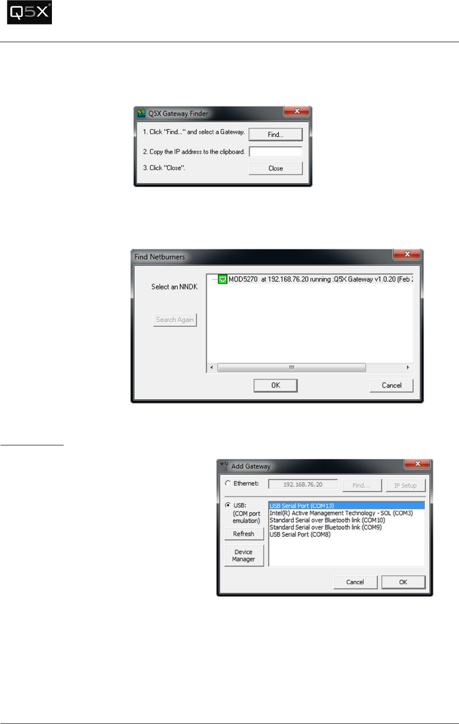
Finding a Gateway
To find a gateway on the net, click the
“Find” button and follow the
instructions.
Setting the IP Address of
a Gateway
If the IP address of the gateway(s) on the network needs to be
configured, click the “Find” button. The following tool will appear to
determine the IP address.
USB Gateways
1.
If adding a USB Gateway, select “USB”
and select the COM port of the gateway.
2. Click “OK”.
Note: The name of the gateway’s COM port
will be “USB Serial Port”.
If the USB Gateway does not appear in the
list, see the Troubleshooting section on how
to diagnose the issue.
IMPORTANT: The COM port must be in the
range of COM1 to COM16. If the COM port
is above COM16, see the troubleshooting
section to change it to a lower COM port.
QT-5000 & Remote Control Audio System
Revision: 6
QT
-
5000 and RCAS User Manual v6.docx
Page
13
of
30
Q5X Systems, Inc. 2012
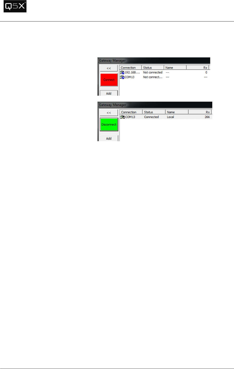
Connecting to the Gateways
To start the communications to the
Gateways, from the Gateway Manager
window, click the “Connect” button.

QT-5000 & Remote Control Audio System
Revision: 6
QT
-
5000 and RCAS User Manual v6.docx
Page
14
of
30
Q5X Systems, Inc. 2012
Configuring the Gateway
To
configure
the
Gateway,
from the in
the
Gateway
Manager,
select the
Gateway to
be
configured,
then click
on the
“Config”
button.
Note: The
Gateway
must be
connected
before
trying to
Configure
the
Gateway.
QT-5000 & Remote Control Audio System
Revision: 6
QT
-
5000 and RCAS User Manual v6.docx
Page
15
of
30
Q5X Systems, Inc. 2012
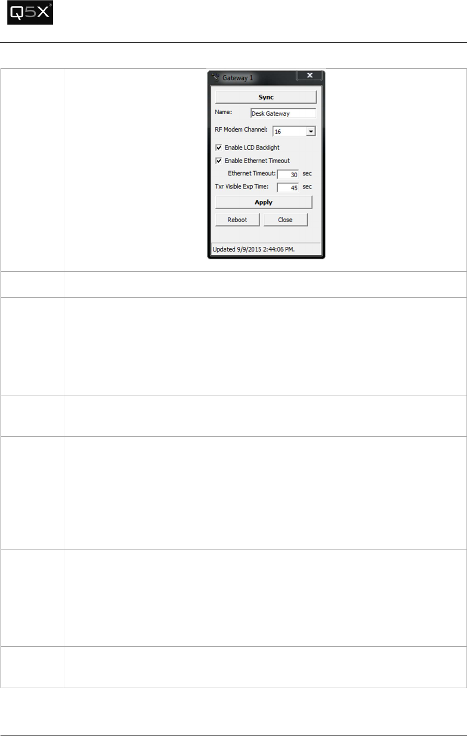
The
following
window
will appear.
Name
This is the friendly name of the Gateway.
RF Modem
Channel
The RF Modem Channel is the 2.4 GHz telemetry channel that the Gateway uses to
communicate to the Transmitters.
Note: The 2.4 GHz spectrum used occupies the same bandwidth as Wi-Fi, Bluetooth and
other unlicensed ISM devices. In most environments, channel 16 is the clearest
channel.
Enable LCD
Backlight
This parameter will enable/disable the b
acklight of the
Gateway.
Enable
Ethernet
Timeout
(Network
Gateway
only)
In the rare case that the software or gateway loses connection, the Gateway will
automatically disconnect after a period of “silence” from the software. The software is
designed to send communication at regular intervals to let the Gateway know that it is
still active.
Check this checkbox to enable this feature.
Ethernet
Timeout
(Network
Gateway
only)
This is the period of time (in seconds) of silence
from the software
that the Gateway
waits before disconnecting.
Tx
r
Visible
Exp Time
Each Gateway keeps a
list
of all the transmitters that it receives heartbeats from. The
Transmitter Visible Expiry Time parameter is the amount of time (in seconds) that
elapses before the Gateway removes the transmitter from the Visible List.
QT-5000 & Remote Control Audio System
Revision: 6
QT
-
5000 and RCAS User Manual v6.docx
Page
16
of
30
Q5X Systems, Inc. 2012
Session Setup
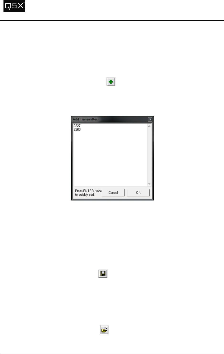
Adding a Transmitter to the Session
1. To add transmitters to the session:
• From the “Transmitter” menu, select “Add…”.
• Or, click the Add Transmitter button from the toolbar.
• Or, type Ctrl+T.
2. Type the serial numbers of the transmitters to be added. Several transmitters can be added at
once as seen below.
3. Click OK to add the transmitters to the session.
Saving a Session
After adding the desired transmitters, the list can be saved as a session and opened at a later time.
To save the session:
• From the File menu, click “Save Session…”
• Or, click the Save Session button
• Or, type Ctrl+S
Opening a Session
To open a previously saved session:
• From the File menu, click “Open Session…”
• Or, click the Open Session button
• Or, type Ctrl+O
QT-5000 & Remote Control Audio System
Revision: 6
QT
-
5000 and RCAS User Manual v6.docx
Page
17
of
30
Q5X Systems, Inc. 2012
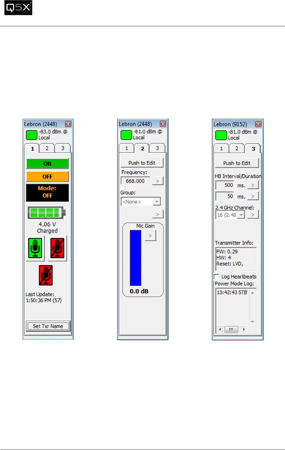
Transmitter Panel
Each transmitter has a panel with 3 tabs:
• Status & Control
• Configuration
• Miscellaneous.
Tab
1
-
Status & Control
Tab
2
-
Configuration
Tab
3
-
Miscellaneous

QT-5000 & Remote Control Audio System
Revision: 6
QT
-
5000 and RCAS User Manual v6.docx
Page
18
of
30
Q5X Systems, Inc. 2012
Tab 1 – Status and Control Tab
Heartbeat Indicator
Each transmitter sends out a heartbeat approximately every
2.
5
seconds that contains all status and configuration information.
At the top of the transmitter panel is the heartbeat indicator.
Each time a heartbeat is received by the Gateway, the indicator
will turn to a bright green.
As time passes, the indicator will fade to black. When another
heartbeat is received, it will return to bright green.
At the bottom of the transmitter panel, a timestamp displays the
time of the last received heartbeat.
Power Status and Control
The following panel contains
the power control buttons
and status.
Power On
Power Off
Underneath the power buttons is the current power state.
Indicates that the command to change the
power state has been sent and that the software is waiting for a
response.
Battery
Indicator
The battery indicator displays the current
state of the battery.
4.100 V = 100%
3.300 V = 0%
When the transmitter is plugged into a charger, the status will
display “Charging…” underneath the battery voltage.
QT-5000 & Remote Control Audio System
Revision: 6
QT
-
5000 and RCAS User Manual v6.docx
Page
19
of
30
Q5X Systems, Inc. 2012
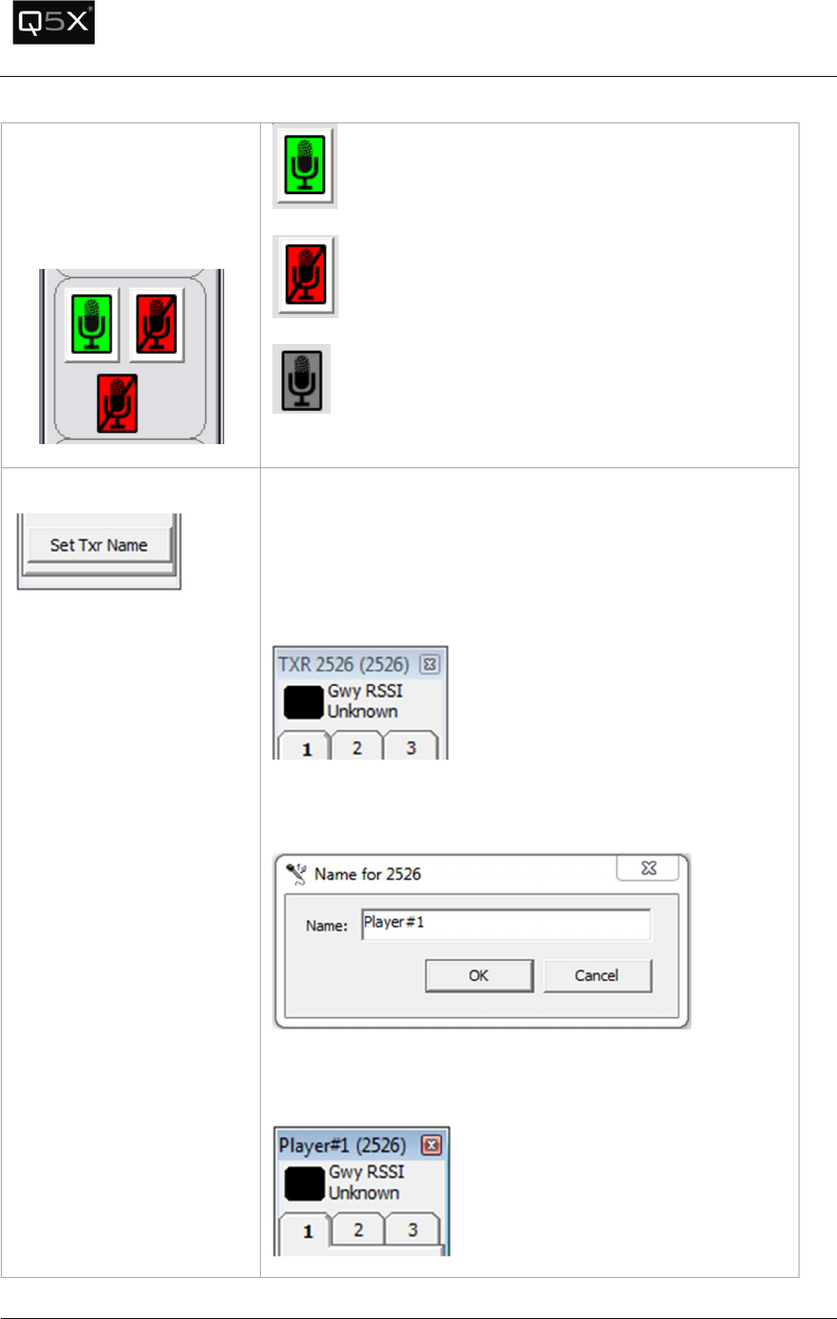
Mute Control
The following panel contains
the mute control buttons and
status.
Mute On
Mute Off
Indicates that the command to change the mute state
has been sent and that the software is waiting for a response.
Set Transmitter Name
To simplify the identification of a transmitter, an alias or name
can be attached to the transmitter in the session.
When the name is not set, the title bar of the transmitter panel
will display “TXR” and the serial number, for example “TXR
2267”.
To set the Transmitter’s name, press the “Set Txr Name” button
and enter the “friendly” name of the transmitter.
The new name will now be displayed with the serial number in
brackets.
QT-5000 & Remote Control Audio System
Revision: 6
QT
-
5000 and RCAS User Manual v6.docx
Page
20
of
30
Q5X Systems, Inc. 2012
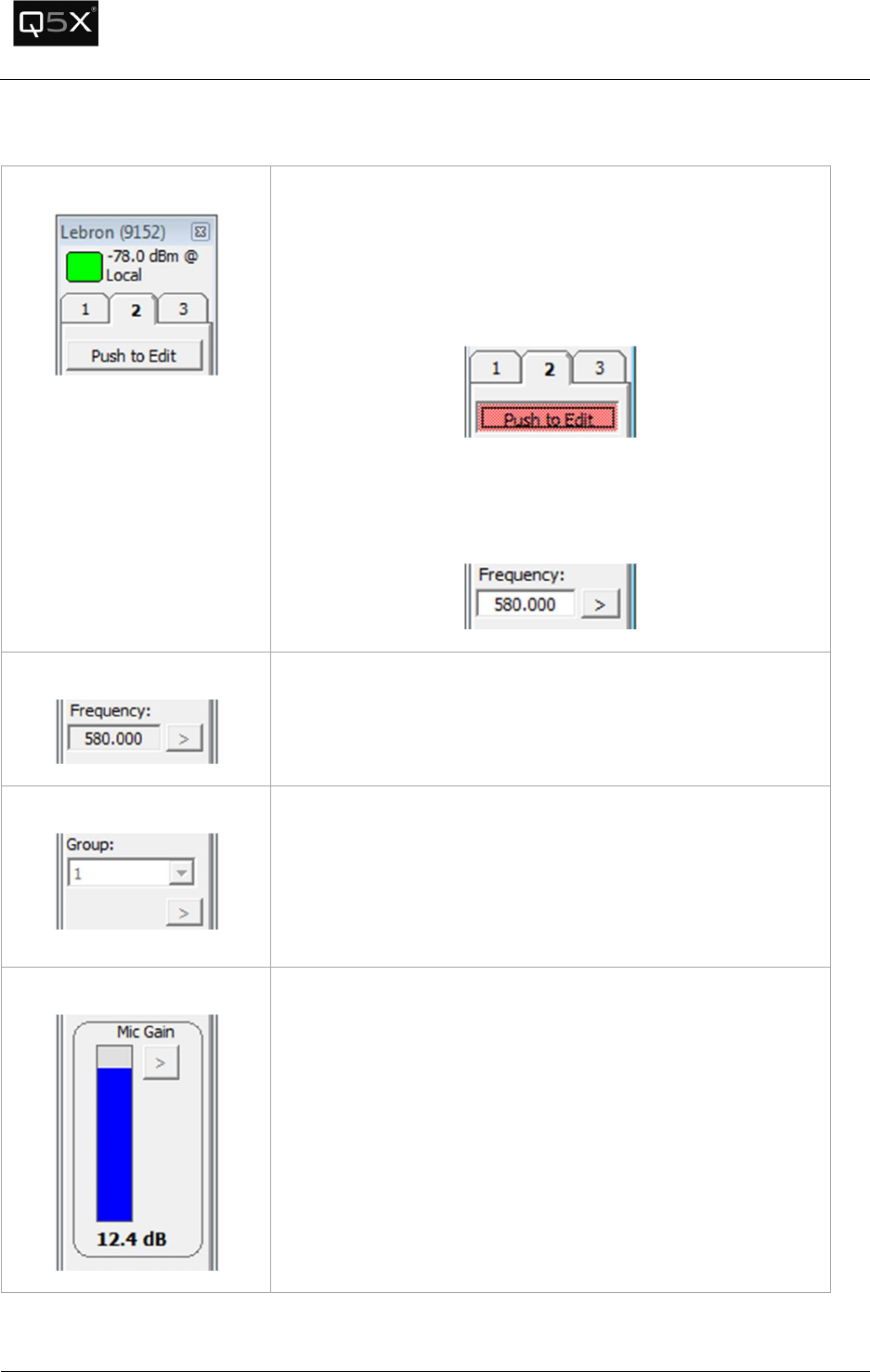
Tab 2 – Configuration Tab
Configuration Tab
Tab 2 contains most of the configurable settings of the
transmitter.
To edit any of settings, one must first put the panel into Edit
mode by pressing the Edit button. Once it is in Edit mode, the
button will turn pink.
Each parameter has a “set” button to the right (indicated by a
‘>’). After the desired value is entered, press the “set” button
to send the value to the transmitter.
Frequency
This parameter is the frequency that the audio transmits on.
Range: 600.000 to 700.000 MHz
Step: 25 kHz.
Group
The transmitters can be powered on and off in groups, making it
simpler to control batches of transmitters. A transmitter can be
set to one of 31 groups.
To set the group names, see the section “Customizing Group
Names”.
Mic Gain
If a microphone is clipping, the Mic Gain can attenuate the gain
of the microphone from 0 to -6.5 dB.
QT-5000 & Remote Control Audio System
Revision: 6
QT
-
5000 and RCAS User Manual v6.docx
Page
21
of
30
Q5X Systems, Inc. 2012
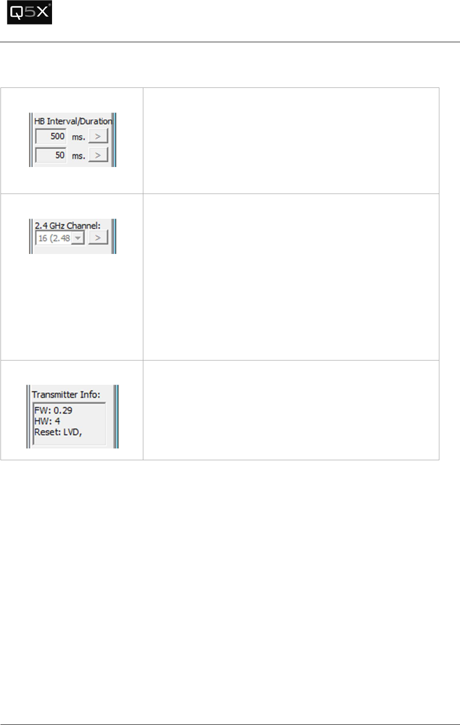
Tab 3 – Miscellaneous Tab
Heartbeat
Interval/Duration
The Heartbeat Interval sets how long a transmitter waits until a
heartbeat is sent out.
The Heartbeat Duration sets how long a transmitter waits for a
reply to a heartbeat from the Gateway/Software.
It is recommended that the values be left as the defaults.
RF Modem Channel
The RF Modem Channel is the 2.4 GHz telemetry channel that
the Transmitter(s) use to communicate to the Gateway(s).
Note: The 2.4 GHz spectrum used occupies the same band as Wi-
Fi, Bluetooth and other unlicensed ISM devices. In most
environments, channel 16 is the clearest channel.
Warning: Exercise caution when changing this parameter –
after the channel is changed, the software will not be able to
communicate with the Transmitter until the Gateway channel
is changed to match.
Version Information
The hardware and firmware version information of the
transmitter is displayed in the transmitter info text box.
QT-5000 & Remote Control Audio System
Revision: 6
QT
-
5000 and RCAS User Manual v6.docx
Page
22
of
30
Q5X Systems, Inc. 2012
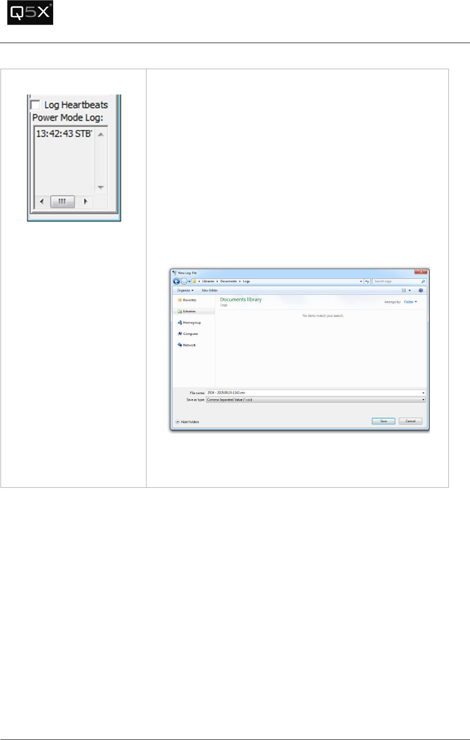
Heartbeat Logging
When a heartbeat is received from the transmitter, it contains
configuration and status information. This information can be
logged for diagnostic and informational purposes.
When enabled, the following information is logged to a comma
separated value (CSV) file:
• Timestamp
• Battery Voltage
• Power Mode (On/Standby)
• Transmitter RSSI
• Gateway RSSI
To enable logging, click the “Log Heartbeats” checkbox. The
serial number, date and time is the default filename. Click Save.
Each time a heartbeat is received, the heartbeat information will
be stored in the file. To stop logging, uncheck the “Log
Heartbeats” checkbox.
QT-5000 & Remote Control Audio System
Revision: 6
QT
-
5000 and RCAS User Manual v6.docx
Page
23
of
30
Q5X Systems, Inc. 2012
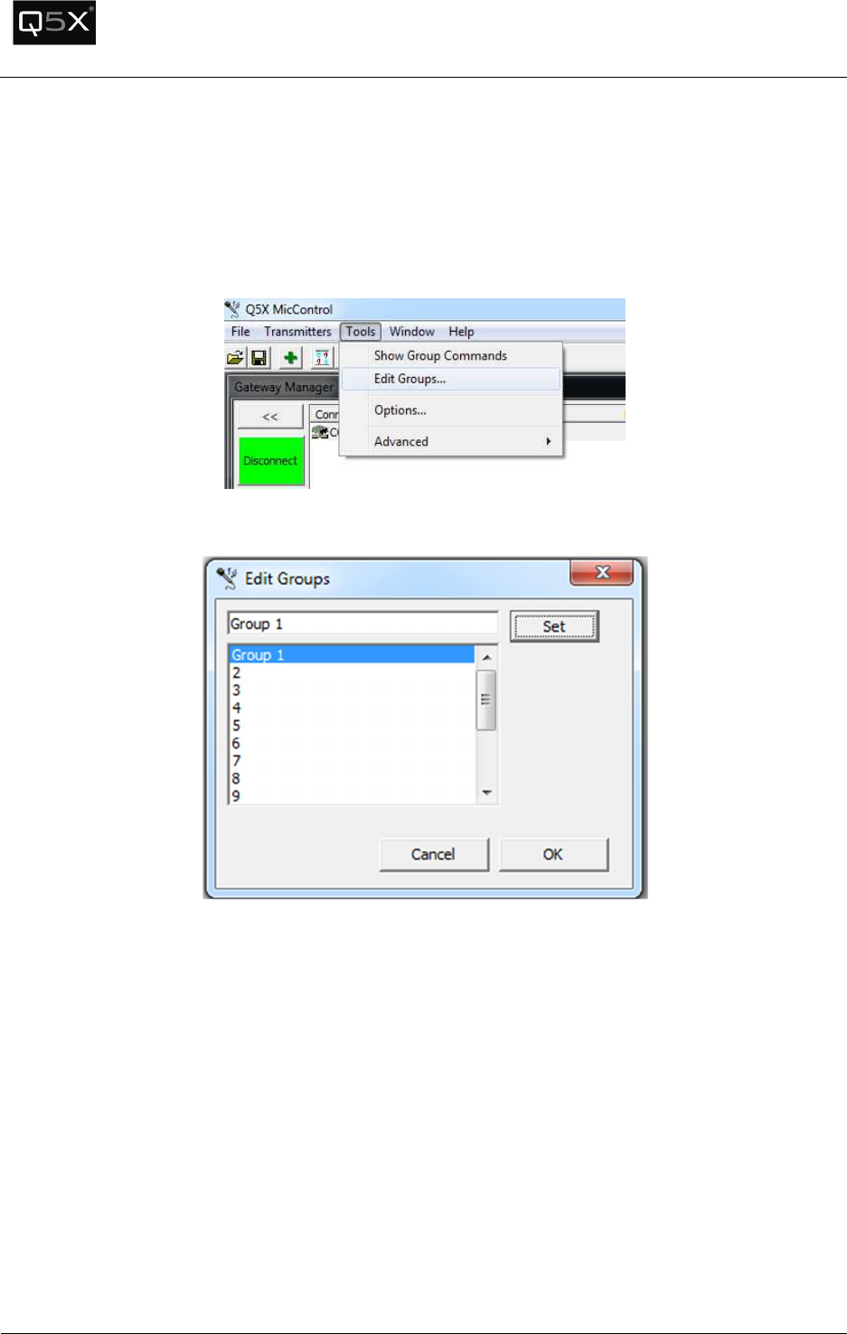
Customizing Group Names
The Transmitters can be configured into groups so they can be powered on and off in batches.
To customize the Group Names:
1. Open the Group Editor by clicking the Tools menu and selecting “Edit Groups…”.
2. Select the group to change. Edit the name and press “Set”.
3. Click OK when all edits are complete.
QT-5000 & Remote Control Audio System
Revision: 6
QT
-
5000 and RCAS User Manual v6.docx
Page
24
of
30
Q5X Systems, Inc. 2012
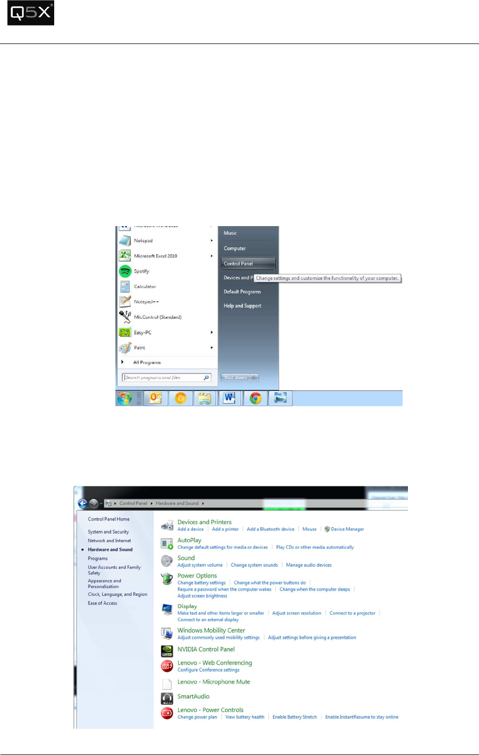
Troubleshooting
The USB port does not appear in the Gateway Manager.
Verify that the drivers are installed properly.
To confirm that the drivers are installed properly, open the Device Manager and locate the installed
Gateways (USB Serial Ports).
1. Click the Start menu -> Control Panel
2. Click on “Hardware and Sound”. Click on “Device Manager” below the “Devices and
Printers”heading. Note: Depending on the operating system and other Start menu settings,
there may be alternate methods of opening the Device Manager.
QT-5000 & Remote Control Audio System
Revision: 6
QT
-
5000 and RCAS User Manual v6.docx
Page
25
of
30
Q5X Systems, Inc. 2012
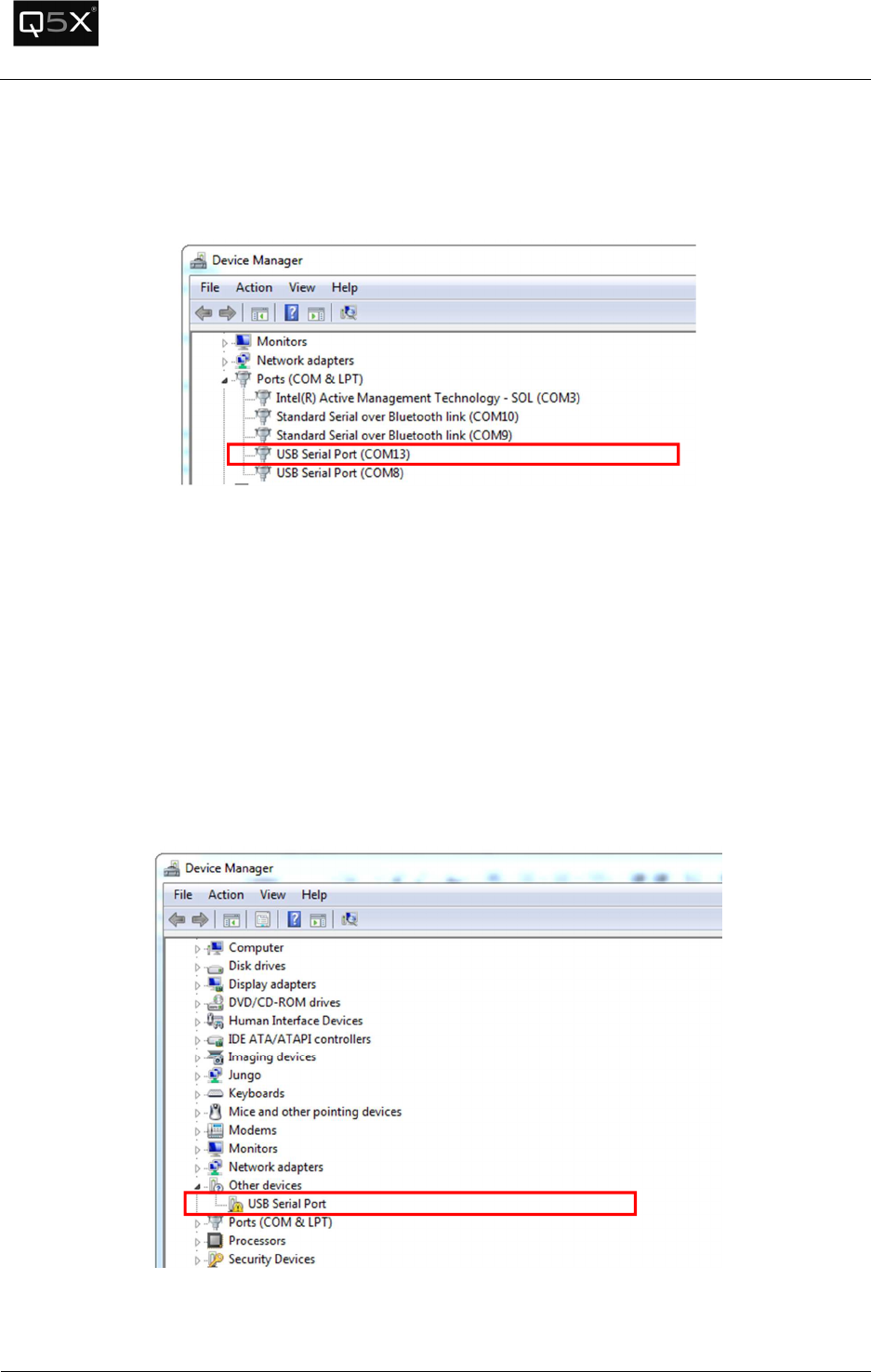
3. Scroll down “Ports (COM & LPT)” section. The Gateways should appear as “USB Serial Port
(COMxx). To confirm if the USB Serial Port driver is installed properly, disconnect and reconnect
the Gateway. The Gateway should disappear and reappear in the list.
4. If the USB Serial Port does not appear under “Ports (COM & LPT)”, look under “Other Devices” for
“USB Serial Port”. If it appears with an exclamation mark, see the Appendix – Installing USB
Drivers.
QT-5000 & Remote Control Audio System
Revision: 6
QT
-
5000 and RCAS User Manual v6.docx
Page
26
of
30
Q5X Systems, Inc. 2012
The COM port designation is higher than COM16
The MicControl software will only recognize a valid COM port number up to COM16. If the Gateway is
configured as a port higher than COM16, follow these instructions to change the COM port number.
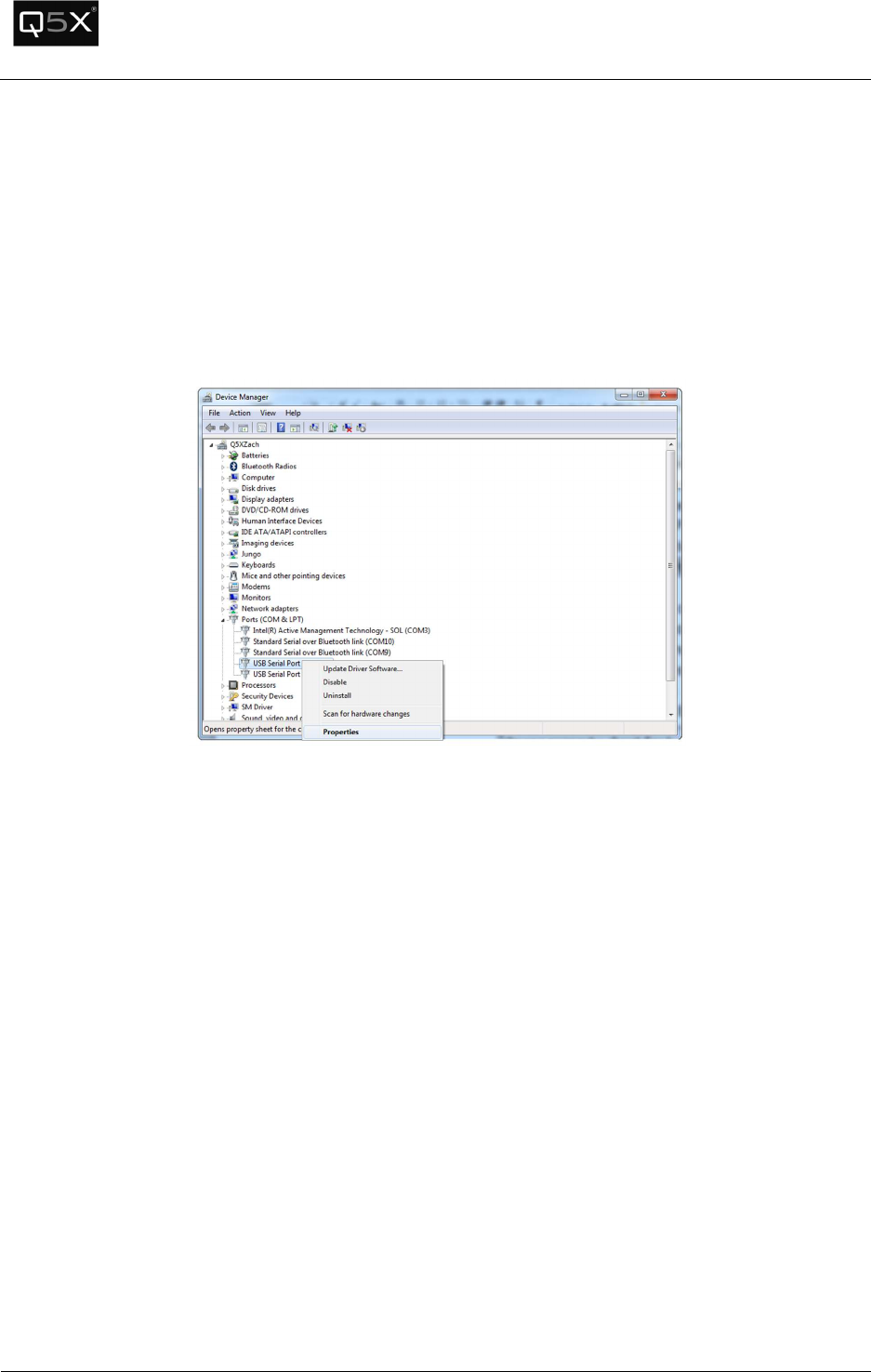
1. Locate the USB Serial Port in the Device Manager (see the instructions above on how to locate
the USB Serial Port number).
2. Right-click on the USB Serial Port to be changed and select “Properties”.
3. Select the “Port Settings” tab and click the “Advanced” button.
4. In the “COM Port Number” field, select a port from COM2 to COM16.
Note: Select a COM port that is not marked as “(in use)”. If none are available, choose one that
is the least likely to be active. Click “OK” to the warning that will appear.
5. Click “OK”.
6. Disconnect and reconnect the Gateway. Verify that the COM port was changed.
The transmitters are charged and the status light is blinking, but the
status heartbeats are not appearing in the software.
Ensure that the 2.4 GHz telemetry channel of the transmitter and the gateway match.

QT-5000 & Remote Control Audio System
Revision: 6
QT
-
5000 and RCAS User Manual v6.docx
Page
27
of
30
Q5X Systems, Inc. 2012
Specifications
Technical Data UHF Radio
RF Carrier Frequency Range: 614 MHz – 698 MHz
Working Range – 500m (line of sight, outdoors for a single system)
Note: Actual working range depends on RF signal absorption, reflection and interference
RF Power Output: 81.1 mW (max)
Antenna impedance: 50 Ω Impedance
Technical Data 802.15.4 Radio
RF Power Output: 0.7 mW (max)
RF Carrier Frequency Range: 2.405 GHz – 2.480 GHz
Technical Data QT-5000 Module
Power Requirements: 3.7V (4.2V Max)
Current Drain: 140 mA
Max Input Audio Signal: 1 VRMS
Audio Gain Adjustment Range: 0 dB – 14 dB
Overall Dimensions: 37mmX12.9mmx57mm (Battery on top of module)
Net Weight: 43 g
QT-5000 Module Antennas
UHF Radio Antenna: Uses a permanently attached wire antenna which is factory installed with
max gain of 3 dBi.
Manufacturer: Q5X
Type: ¼ Wave UHF Wire antenna soldered to the PCB
Frequency Range:
614MHz – 698MHz
Max Gain (dBi): 3 dBi
802.15.4 Radio Antenna: Uses a permanently attached wire antenna which is factory installed
with max gain of 3 dBi
Manufacturer:
Q5X
Type:
¼ Wave 802.15.4 Wire antenna soldered to the PCB
Frequency Range:
2.405GHz – 2.480GHz
Max Gain (dBi):
3 dBi
QT-5000 & Remote Control Audio System
Revision: 6
QT
-
5000 and RCAS User Manual v6.docx
Page
28
of
30
Q5X Systems, Inc. 2012
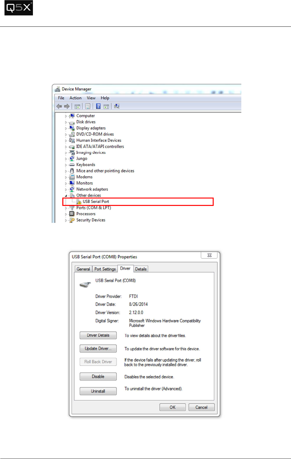
Appendix - Installing the USB Driver
Find the Gateway in the device manager as shown in verify that the drivers are installed properly. Right
click on the USB Serial Port and select properties.
Select the driver tab.
0
Click on the Update Driver button.
QT-5000 & Remote Control Audio System
Revision: 6
QT
-
5000 and RCAS User Manual v6.docx
Page
29
of
30
Q5X Systems, Inc. 2012
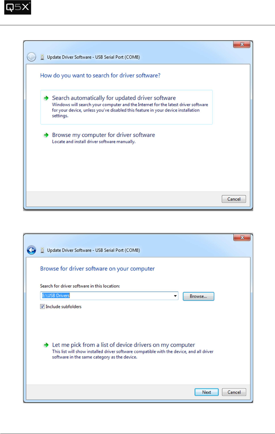
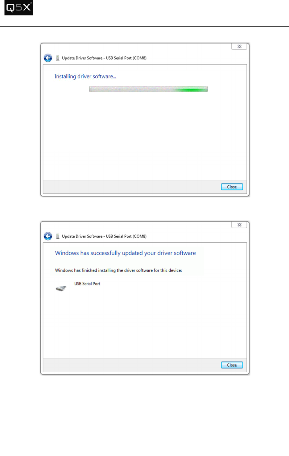
Select Browse my computer for driver software
Browse for the location of the USB drivers. Press next to install the drivers.
QT-5000 & Remote Control Audio System
Revision: 6
QT
-
5000 and RCAS User Manual v6.docx
Page
30
of
30
Q5X Systems, Inc. 2012
Press close to complete the installation.