Quatech Usb To Rs 232 422 485 Isolated Converter Ssu2 400I Users Manual
SSU2-400I to the manual 573d55a5-b83c-4422-abc1-49c0b09286f5
2015-02-05
: Quatech Quatech-Usb-To-Rs-232-422-485-Isolated-Converter-Ssu2-400I-Users-Manual-492918 quatech-usb-to-rs-232-422-485-isolated-converter-ssu2-400i-users-manual-492918 quatech pdf
Open the PDF directly: View PDF ![]() .
.
Page Count: 24
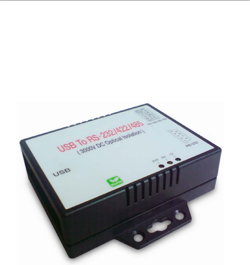
USB to RS-232/422/485
Isolated Converter
Quatech Model SSU2-400I
Operation Manual
1
First Edition, Jun 2008

2
Table of Contents
1. Introduction ……………………………………………… 2
2. Package checklist …………………………………………… 3
3. Product Specification …………………………………… 4
4. Product Panel Views Description …………………… 7
Product Views …………………………………… 7
USB Type B Connector ……………………………………… 7
Serial I/O Port of RS-232/422/485 ………………………..… 8
Terminator …………………………………………………… 8
LED Indicators ……………………………………………… 9
5. Driver installation …………………………… 10
Driver Installation …………………………………………… 10
6. Hardware Installation & Setup ……………………… 15
Hardware installation ………………………………………… 15
Hardware setup ………………………………………………… 17
Appendix A - Pin Outs and Cable Wiring ………… 21
USB Layout Diagram ………………………………………… 21
RS-232 Pin Assignment ……………………………………… 21
RS-232 Wiring Diagram ……………………………………… 22
RS-422 Pin Assignment ……………………………………… 22
RS-422 Wiring Diagram ……………………………………… 22
RS-485 Wiring Diagram ……………………………………… 22

3
1
1
Introduction
Thank you for your purchase of the USB to serial adapter. Featuring USB
(Universal Serial Bus) interface technology, it is converted the USB to RS-232 or
industrial RS422/485, so it can be easily adopted for industrial machines with
RS232 or RS422/485 interfaces. The USB to Serial converter is fully compatible
with the USB V1.02.0 . This converter is USB bus powered and does not need
any power adapter. You can connect a PC USB port or USB hub to this converter
via USB cable and High-Speed RS-232/422/485 serial port (Auto-Detection) which
features easy connectivity for traditional serial devices in your working
environments.
The RS232 standard supports handshaking signals (such as RTS, CTS) and
full-duplex communication. For the RS485 control, it is completely transparent to
user and their software written for Half-Duplex COM works without any extra
modification effort.
The USB to Serial Isolated Converter meets the industrial level as it provides 3000
VDC of isolation to protect the host computer or other connected equipments from
ground loops and destructive voltage spikes on the RS-232/422/485 data lines. It
also offers internal surge-protection on data lines. Internal high-speed transient
suppressors on each data line to protect it from dangerous voltages levels or
spikes.

4
2
2
Package checklist
This product is shipped with the following items:
1 unit of USB to RS-232/422/485 Isolated converter
1 unit of A type to B type USB cable
User Operation Manual
Software CD
NOTE: Notify your sales representative if any of the above items is missing or
damaged

5
3
3
Product Specification
Serial Port
RS-232
● No. of Ports : RS-232 * 1 Port
● Port Type : DB9 male
● RS-232 Signals : DCD , RX , TX , GND , RTS , CTS , DTR , DSR
● Receive buffer : 576 Byte
● Transmit buffer : 640 Byte
● Baud Rate Speed : 300 bps921.6k bps
● Parity :None , Odd , Even , Space , Mark
● Data Bit : 5 , 6 , 7 , 8
● Stop Bit: Auto-Detection : 1 , 1.5 , 2,
● Flow Control : X-On / X-Off or Hardware
● Optical isolation protection : 3000V DC
● Connected Serial port type identification : Auto-Detection
● 15KV ESD for all signal
6
RS-422/485
● No. of Ports : 422/485 * 1 Port (Terminal Block)
● RS-422 Signals : RxD+ , RxD- , TxD+ , TxD- in Full-duplex (Surge Protection)
● RS-485 Signals : Data+ , Data- in Half-duplex (Surge Protection)
● Receive buffer : 576 Byte
● Transmit buffer : 640 Byte
● Baud Rate Speed : 300 bps230.4k bps
● Built-in RS-422/RS-485 Terminal Resister (Surge Protection)
● Optical isolation protection : 3000V DC
● Connected Serial port type identification : Auto-Detection
● Built in Terminal 100 Ohm Terminal resistor SW selection ON/OFF
● 15KV ESD for all signal
USB Port
No. of Ports : USB * 1 Port
● Fully compatible with the USB V1.0, V1.2, V2.0
● USB type B connector
● Baud Rates : Full speed 12 Mbps.
Driver OS Support
● Windows – 98E / 2000 / XP / Server 2003 /Vista , Mac osx / os9 , Linux 2.4 / 2.6
Power :USB bus power as voltage DC +5V
Led Lamp :
SYS (Red), Rx (Orange), Tx (Green)
Environment :
● Operating Temperature: 070
● Storage Temperature : -2085
7
Humidity: 5-95% RH
Dimensions : 88 * 91 * 27 mm ( W * D * H )
WEIGHT : 94 gm
Regulatory Approvals :
● EMC : FCC Class A, CE Class A
● WARRANTY : 1 Year
8
4
4
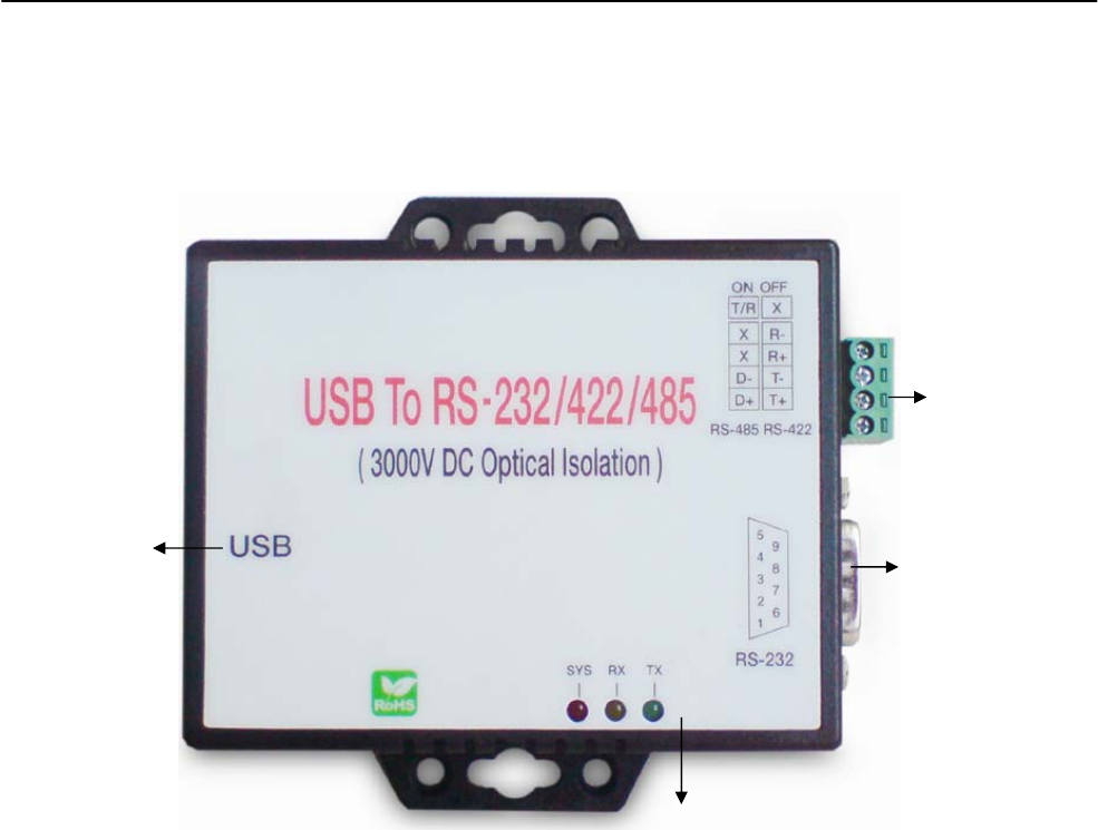
Product Panel Views Description
Product Views
USB Type B Connector
Power Outlet - The USB to Serial converter is powered by USB (Universal
Serial Bus) port a single 5V DC (Inner positive/outer negative) power supply
and 500mA of current. If the power is properly supplied, the SYS indicator of
red color LED will be on.
Serial I/O Port
RS-232
LED Indicators
USB Type B
Connector
Serial I/O Port
RS422/485

9
This converter’s USB port is a USB type B connector and it is fully compatible
with the USB V1.1 ~ 2.0.
Serial I/O Port
Serial I/O Port of RS-232/422/485
To connected the serial data cable between the converter and the serial
device. Follow the parameter setup procedures to configure the converter
(see the following chapters).
Terminator (DIP Switches)
The purpose of the Terminator (DIP Switches) is for compensating signal
attenuation in a long distance connection at RS-485/422. To activate signal
compensation function, please set the dip switch 1 & 2 to “ON” position. To
disable signal compensation function, please set the dip switch to “OFF”
position.
Serial I/O Port
RS-485/RS-422
Terminator
Serial I/O Port
RS232
USB Type B Port
10
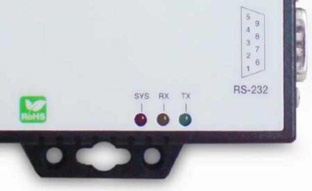
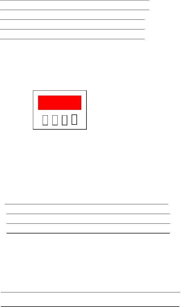
LED Indicators
SYS (Red)
It is a power indicator (When the power is on, the SYS LED will be on.)
RX (Orange)
Data received indicator (When data are received from the USB, the RX LED
will be on.)
TX (Green)
Data sent indicator (When data are sent out to the USB, the TX LED will be
on.)
11
5
5
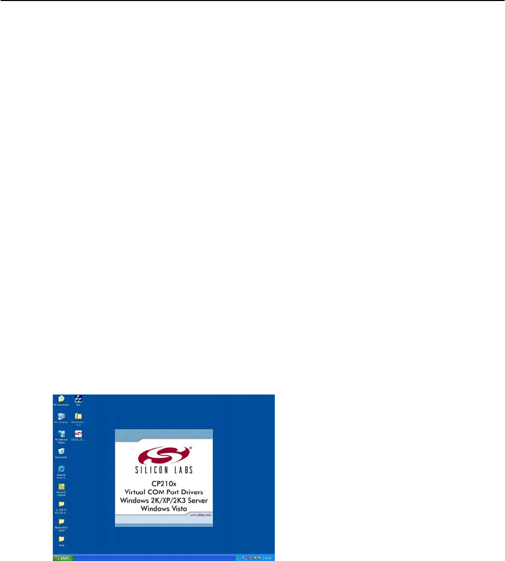
Driver Installation
When setting up this converter for the first time, you have to install the driver
CP201x first in your computer device before connecting it. There are several
OS as Windows 98 / XP / 2000 / Vista …, Linux …, Mac … The utility CD is
enclosed in the device box.
The driver of all these USB to RS-232/422/485 converters must be installed first
before you use it.
Driver Installation
When connecting this converter for the first time, you have to install the driver
into your computer first.
A. Install CP210x_VCP_Win2K_XP_S2K3 software
Through CD-ROM and find adaptable OS to your computer equipment.
B. Choose “Next” Icon
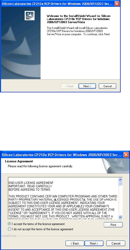
12
If your computer equipment is running Windows OS that the pop-up
screen of installing massage will be showed as “CP210x VCP Drivers for
Windows 2000/XP/2003 Server/Vista on your computer” and then to Click
“Next” icon for going to next step.
C. Choose “Accept” item of license agreement
After reading the license agreement then if you agree the terms to choose
the item “I accept the term of the license agreement”.
13
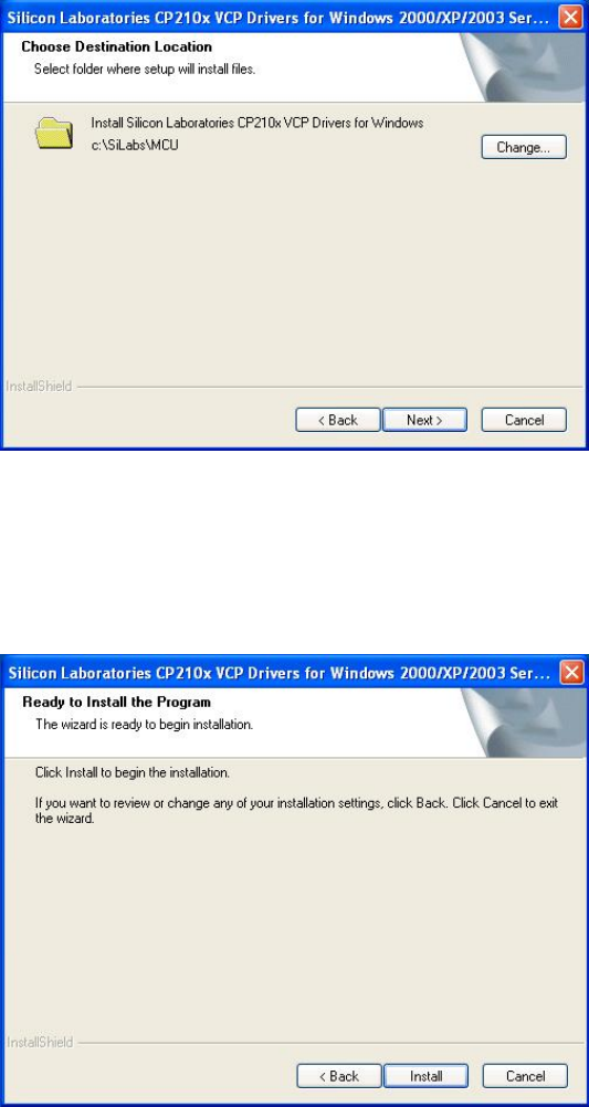
D. Choose destination location
It is for saving the CP201x driver software in destination location of
computer.
E. Execute the program installation
Click the “install” icon to begin installation of CP210x driver.
14
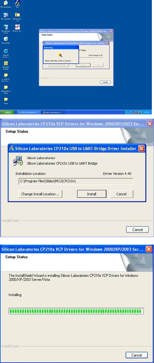
F. Scan and install CP210x USB to UART Bridge Driver Installer
After click “Install” icon, system is going to scan CP210x USB to UART
Bridge driver installer and installation location.

15
G. “System Settings Change” Notice
The massage is notified you that your computer has been changed after
installing of CP210x USB to UART Bridge Driver Installer. The new
setting will take effect after restarting your computer.
H. InstallShield Wizard Complete
CP201x driver has successfully installed and click “Finish” icon for exiting
the wizard.
16
6
6
Hardware Installation & Setup
Hardware Installation
1. Power on your computer and until OS is ready after booting
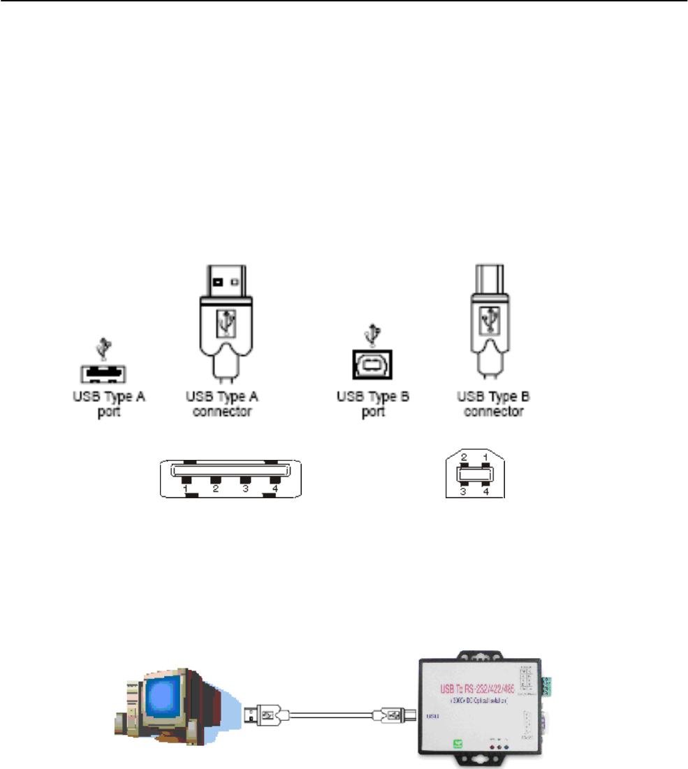
2. USB cables have two distinct connectors. The Type A connector is used to
connect the cable from a USB device to the Type A port on a computer or USB
hub. The Type B connector is used to attach the USB cable to a USB device.
3. Connect USB cable between a PC USB port (Or USB hub) and this converter’s
type B USB port.
17
4. Connect the serial port (RS232 or RS422 or RS485) equipments to this USB to
serial converter.
5. After connecting the USB to serial converter, then a massage as “New device
has been connected” will be pop-up on screen. However, the CT201x driver
needs to be installed in PC in advance.
6. The SYS indicator of red LED will be turn into on. The USB to serial converter
is active.

18
Hardware Setup
When the USB to serial converter has successfully connected and you can
setup more detailed parameters by Computer’s Management.
A. Into “Manage” icon in My Computer
Click “My Computer” icon and then press the right side button of mouse.
After you click the manage item on list bar then “Computer Management
(Local) list will be pop-up.

19
B. Choose “Device Manager” and click “Ports(COM & LPT)” in
Device Manager
Click “Device Manager” item, all devices of computer will be list on right
site of screen and then click “Ports (COM & LPT) item for looking for more
COM devices.
C. Detail parameters of CP210x USB to UART Bridge Controller
Click “CP210x USB to UART Bridge Controller” for getting more detail
information of the device.

20
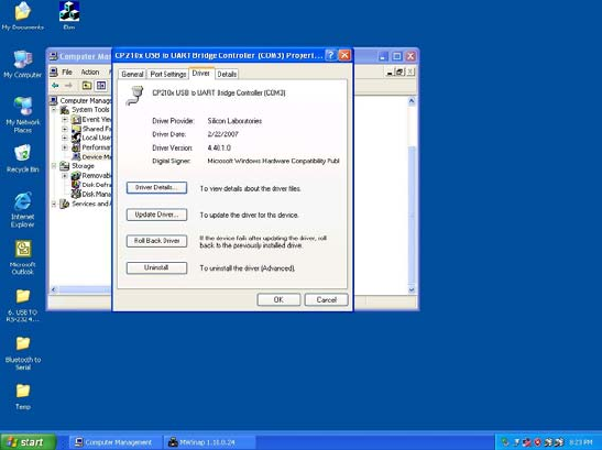
D. Device status of CP210x USB to UART Bridge Controller
This is showing the statues of device and some product general
information. COM port number of device is also display on.
E. “Driver” detail information
This is for checking more detail information of driver in this device.
21
F. “Details” item
It is for checking device ID numbers as device instance ID.
22
A
Ap
pp
pe
en
nd
di
ix
x
A
A
Pin outs and Connector
□
□
□
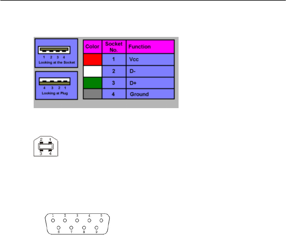
USB Layout Diagram
Type A USB Connector
Type B USB Connector
□
□
□ RS-232 Pin Assignment
The pin assignment scheme for a 9-pin male connector is given below.
PIN 1 : DCD PIN 2 : RXD PIN 3 : TXD PIN 4 : DTR
PIN 5 : GND PIN 6 : DSR PIN 7 : RTS PIN 8 : CTS
PIN 9 : X
□
□
□ RS-232 Wiring Diagram
23
Serial Device USB to RS-232/422/485 Converter
2 RX 3 TX
3 TX 2 RX
5 GND 5 GND
7 RTS 8 CTS
8 CTS 7 RTS
□
□
□ RS-422 Pin Assignment
The pin assignment scheme for a 4-pin RS-422 is given below.
RS-422: PIN 1: T+ PIN 2: T- PIN 3: R+ PIN 4: R-
RS-485: PIN 1: D+ PIN 2: D-
□
□
□ RS-422 Wiring Diagram
Serial Device USB to RS-232/422/485 Converter
R- 2 T-
R+ 1 T+
T- 4 R-
T+ 3 R+
□
□
□ RS-485 Wiring Diagram
Serial Device USB to RS-232/422/485 Converter
D- 2 D-
D+ 1 D+
1 2 3 4
(Flow Control)
(Flow Control)
