Queclink Wireless Solutions GV75 GPS Tracker User Manual GV75 x
Queclink Wireless Solutions Co.,Ltd GPS Tracker GV75 x
Users Manual

GV
7
TRA
7
5UserMan
u
CGV75UM0
0
u
al
0
1
G
GS
M
G
V75
U
M
/GP
TR
A
V
U
ser
RS/G
A
CGV75
U
V
ersion:R
1
Man
u
PSTr
a
U
M001
1
.03
u
al
a
cke
r
r
‐1‐

GV
7
TRA
Do
c
Ver
Dat
Sta
t
Do
c
Ge
n
Qu
e
eng
i
bas
e
und
info
pro
d
the
toc
h
Co
p
Thi
s
Wir
e
co
m
are
regi
s
wit
h
7
5UserMan
u
CGV75UM0
0
c
umentTitl
e
sion
e
t
us
c
umentCo
n
n
eralNotes
e
clinkoffers
i
neeringeff
o
e
duponreq
ertakenan
y
rmationtha
d
uctdesign
e
customero
r
h
ange.
p
yright
s
document
e
lessSoluti
o
m
munication
liabletoth
e
s
trationofa
h
outnotice
a
u
al
0
1
e
n
trolID
thisinfor
m
o
rtsthatus
e
uirementss
p
y
independ
tmaybein
e
dbyQuecl
i
r
thecustom
containspr
o
o
nsCo.,Lt
ofthecon
t
e
paymento
f
utilitymod
e
a
tanytime.
GV75User
1.03
2016‐04‐1
5
Release
TRACGV75
m
ationasa
e
theprodu
c
p
ecificallyp
r
entsearch
thecustom
i
nkwithina
er’ssystem
o
prietaryte
c
d.Thecop
t
entsthere
o
f
damages.
A
e
lordesign.
Manual
5
UM001
serviceto
i
c
tsdesigne
d
r
ovidedto
Q
foradditi
o
er’spossess
largerelec
t
integrator.
A
c
hnicalinfo
r
yingofthi
s
o
f,areforbi
d
A
llrightsar
e
Allspecific
a
i
tscustome
r
d
byQuecli
n
Q
ueclinkbyt
h
o
nalreleva
n
ion.Further
t
ronicsyste
m
A
llspecificat
i
r
mationwhi
s
documen
t
d
denwitho
u
e
reservedi
n
a
tionssuppli
e
r
s,tosupp
o
n
k.Theinfo
r
h
ecustome
r
n
tinformat
i
more,syste
m
m
remainst
i
onssupplie
d
chisthep
r
t
,distributi
o
u
texpressa
n
theevent
o
e
dhereinar
o
rtapplicati
r
mationpro
v
r
s.Queclink
ion,includi
m
validatio
n
heresponsi
b
d
hereinare
r
opertyof
Q
o
ntoothe
uthority.Of
f
o
fapatent
g
esubjectto
‐2‐
onand
v
idedis
hasnot
ngany
n
ofthis
b
ilityof
subject
Q
ueclink
rs,and
f
enders
g
rantor
change

GV
7
TRA
Con
t
Tabl
Figu
0.R
e
1.I
n
1.1.
1.2.
2.P
r
2.1.
2.2.
2.3.
3.G
e
3.1.
3.2.
3.3.
3.4.
3.5.
3.6.
3.7.
3.8.
4.T
r
4.1.
4.2.
5.F
C
7
5UserMan
u
CGV75UM0
0
t
ents...........
eIndex........
reIndex......
e
visionHisto
r
n
troduction..
Reference...
Term sandA
r
oductOver
v
Appearance
PartsList.....
InterfaceDe
f
e
ttingStarte
d
InstallaSIM
Switchonth
PowerConn
e
IgnitionDet
e
DigitalInput
DigitalOutp
u
UARTInterf
a
IndicatorLig
r
oubleshooti
n
Troubleshoo
SafetyInfo..
C
CNOTE……
…
u
al
0
1
...................
.
...................
.
...................
.
r
y................
.
...................
.
...................
.
bbreviations
.
v
iew.............
.
...................
.
...................
.
f
inition........
.
d
.................
.
Card............
.
eDevice......
.
e
ction..........
.
e
ction..........
.
....................
.
u
t.................
.
a
ce...............
.
htDescriptio
n
gandSafet
y
ting.............
.
....................
.
…
…………………
.
..................
.
.
..................
.
.
..................
.
.
..................
.
.
..................
.
.
..................
.
.
..................
.
.
..................
.
.
..................
.
.
..................
.
.
..................
.
.
..................
.
.
....................
.
....................
.
....................
.
....................
.
....................
.
....................
.
....................
n..................
y
Info............
.
....................
.
....................
…………………
…
Conten
t
.
..................
.
.
..................
.
.
..................
.
.
..................
.
.
..................
.
.
..................
.
.
..................
.
.
..................
.
.
..................
.
.
..................
.
.
..................
.
.
..................
.
....................
....................
....................
....................
....................
....................
....................
....................
....................
....................
....................
…
………………
…
t
s
.
..................
.
.
..................
.
.
..................
.
.
..................
.
.
..................
.
.
..................
.
.
..................
.
.
..................
.
.
..................
.
.
..................
.
.
..................
.
.
..................
.
....................
.
....................
.
....................
.
....................
.
....................
.
....................
.
....................
.
....................
.
....................
.
....................
.
....................
.
…
…………………
…
.
..................
.
.
..................
.
.
..................
.
.
..................
.
.
..................
.
.
..................
.
.
..................
.
.
..................
.
.
..................
.
.
..................
.
.
..................
.
.
..................
.
.
....................
.
....................
.
....................
.
....................
.
....................
.
....................
.
....................
.
....................
.
....................
.
....................
.
....................
…
………………
…
.
..................
.
.
..................
.
.
..................
.
.
..................
.
.
..................
.
.
..................
.
.
..................
.
.
..................
.
.
..................
.
.
..................
.
.
..................
.
.
..................
.
....................
....................
....................
....................
....................
....................
....................
....................
....................
....................
....................
…
…………………
‐3‐
.
.........3
.
.........4
.
.........5
.
.........6
.
.........7
.
.........7
.
.........7
.
.........8
.
.........8
.
.........8
.
.........9
.
.......10
........10
........11
........11
........12
........12
........12
........13
........14
........15
........15
........15
……...16

GV
7
TRA
TAB
L
TAB
L
TAB
L
TAB
L
TAB
L
TAB
L
TAB
L
TAB
L
7
5UserMan
u
CGV75UM0
0
L
E1:REFERE
N
L
E2:TERMS
A
L
E3:PARTSL
I
L
E4:DESCRIP
L
E5:ELECTRI
C
L
E6:ELECTRI
C
L
E7:ELECTRI
C
L
E8:DEFINITI
u
al
0
1
N
CE...............
.
A
NDABBREVI
A
I
S
T
................
.
TIONOFGV7
C
ALCHARAC
T
C
ALCONDITI
O
C
ALCONDITI
O
ONOFDEVI
C
.
....................
.
A
TIONS........
.
.
....................
.
5USERCABL
E
T
ERISTICSOFI
O
NSOFNEGA
T
O
NSOFDIGIT
A
C
ESTATUSAN
TableIn
d
.
.....................
.
.....................
.
.....................
E
....................
GNITIONDE
T
T
IVETRIGGE
R
A
LOUTPUTS.
DLED............
d
ex
.....................
.
.....................
.
.....................
.
.....................
.
T
ECTION........
.
R
INPUTS.......
.
.....................
.
.....................
.
.
....................
.
.
....................
.
.
....................
.
.
....................
.
.
....................
.
.
....................
.
.
....................
.
.
....................
.
.
.....................
.
.....................
.
.....................
.
.....................
.
.....................
.
.....................
.
.....................
.
.....................
‐4‐
......7
......7
......8
......9
....12
....12
....13
....14

GV
7
TRA
FIG
U
FIG
U
FIG
U
FIG
U
FIG
U
7
5UserMan
u
CGV75UM0
0
U
RE1:EXAM
P
U
RE2:THEEX
A
U
RE3:THEEX
A
U
RE4:THEC
O
U
RE5:THEC
O
u
al
0
1
P
LECONNECTI
A
MPLECON
N
A
MPLECON
N
O
NNECTIONO
O
NNECTIONO
ONFORNEG
A
N
ECTIONTO
D
N
ECTIONTO
D
FUARTWITH
FUARTWITH
FigureIn
d
A
TIVETRIGG
E
D
RIVEALED...
D
RIVEARELA
Y
FEMALEDB‐
9
EXTERNALD
E
d
ex
E
RINPUTS.....
.
.....................
.
Y
....................
.
9
...................
.
E
VICES..........
.
.
....................
.
.
....................
.
.
....................
.
.
....................
.
.
....................
.
.
.....................
.
.....................
.
.....................
.
.....................
.
.....................
‐5‐
....12
....13
....13
....13
....14

GV
7
TRA
0.
R
R
e
1.
0
1.
0
1.
0
7
5UserMan
u
CGV75UM0
0
R
evision
H
e
vision
0
1
0
2
0
3
u
al
0
1
H
istory
Date
2016‐01‐07
2016‐01‐25
2016‐04‐15
Author
BingoHua
n
AbsideYu
AbsideYu
Descr
i
n
gInitial
AddS
a
Modif
y
i
ptionofC
h
a
fetyInform
a
y
“GettingS
t
h
ange
a
tion
t
art”andpr
o
o
ductappea
r
‐6‐
r
ance
GV
7
TRA
1.
I
The
app
l
devi
GPR
mo
n
3‐a
x
ma
n
pro
v
rep
o
sch
e
1.1
.
S
N
[
1
[
2
1.2
.
A
b
DI
D
O
G
N
7
5UserMan
u
CGV75UM0
0
I
ntroduct
i
GV75isa
c
l
ications.It
h
ces.Itsbuil
t
S/GSMsub
s
n
itoredinre
a
x
isaccelerom
n
agemental
g
v
idedforth
e
o
rtsincludin
g
e
duledGPSp
o
.
Referenc
e
N
Docu
m
1
]GV75
@
2
]@Trac
Protoc
.
Termsan
d
b
breviatio
n
N
O
UT
N
D
u
al
0
1
i
on
c
ompactwa
t
h
asmultiple
t
‐inGPSrec
e
s
ystemsupp
o
a
ltimeorpe
eterallows
m
g
orithms.S
y
e
fullfeatur
e
g
emergenc
y
o
sition.
e
m
entNam
e
@
TrackAirI
n
kAirInte
r
olV1.02.pd
f
d
Abbreviat
n
D
D
D
G
t
erproofGP
S
I/Ointerface
e
iverhassu
p
o
rts850/90
0
riodicallytra
m
otiondete
c
y
stemintegr
a
e
d@Trackp
r
y
,geo‐fence
e
n
terfacePro
t
r
facefor
G
f
Ta
ions
D
escription
D
igitalInput
D
igitalOutpu
G
round
Table2:
T
S
trackerdes
sthatcanb
e
p
eriorsensiti
v
0
/1800/190
0
ckedbyab
a
c
tionandext
e
a
tionisstra
r
otocol.The
boundary
c
t
ocol.doc
G
armin‐FMI
Ta
ble1:Refe
r
t
T
ermsand
A
ignedfora
e
usedfor
m
v
ityandfas
t
0
MHzallo
w
a
ckendserve
e
ndsbattery
ightforward
@Trackpro
t
c
rossings,dri
Remark
r
ence
A
bbreviation
s
widevariet
y
m
onitoringor
t
timetofir
s
w
ingtheGV
7
randmobil
e
lifethrough
ascomplet
e
t
ocolsuppor
t
vingbehavi
o
s
y
ofvehicle
t
controlling
e
s
tfix.Itsqu
a
7
5'slocatio
n
e
devices.Its
sophisticate
d
e
document
a
t
sawidev
a
o
r,lowbatt
e
‐7‐
t
racking
e
xternal
a
dband
n
tobe
built‐in
d
power
a
tionis
a
rietyof
e
ryand
GV
7
TRA
2.
P
2.1
.
2.2
.
Na
m
GV7
GV7
USB
12V
GV7
7
5UserMan
u
CGV75UM0
0
P
roduct
O
.
Appearan
c
.
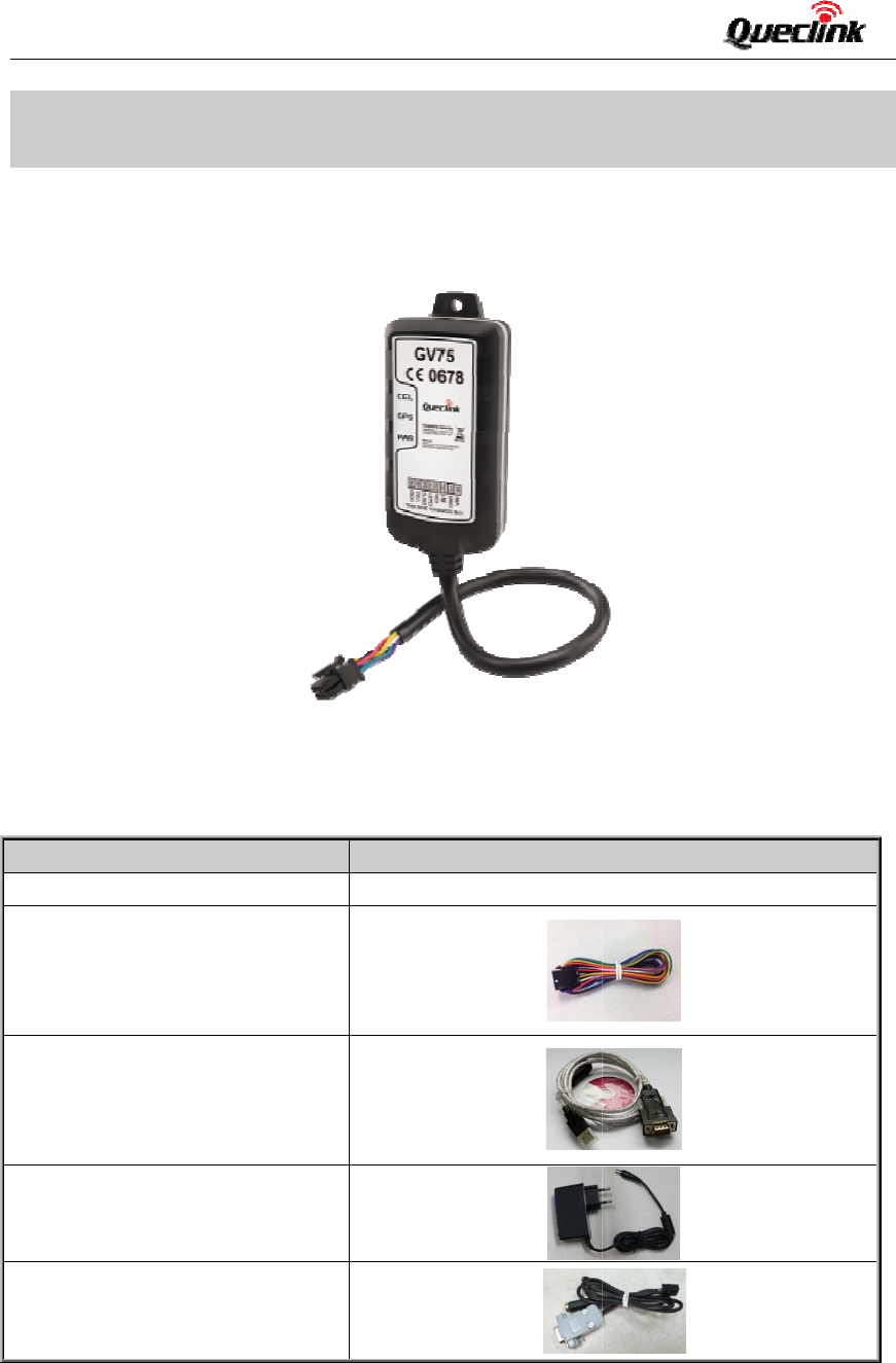
PartsList
m
e
5Tracker
5ExtendCa
b
‐232Cable(o
DCSupply(o
5Configurat
i
u
al
0
1
O
verview
c
e
b
le
ptional)
ptional)
i
onCable(op
t
Figure
T
Pi
c
t
ional)
1. Appearan
T
able3:Part
s
c
ture
ceofGV75
s
List
102mm*4
6
6
mm*20.5m
m
m
‐8‐

GV
7
TRA
2.3
.
The
r
digi
t
tabl
e
In
d
1
2
3
4
5
6
7
8
7
5UserMan
u
CGV75UM0
0
.
Interface
D
r
eare8wire
s
t
alinput,digi
e
.
d
exColou
r
Red
Black
Yello
w
White
Green
Blue
Violet
Grey
u
al
0
1
D
efinition
s
onGV75us
e
taloutput,T
X
r
Descript
Power
Ground
w
Digitali
n
Ignition
Digitalo
u
Digitalo
u
TXD
RXD
e
rcable,whi
c
X
DandRXD,
Table4:De
s
ionCo
Ex
t
Sy
s
n
putDi
g
Ig
n
u
tput2Di
g
u
tput1Di
g
c
hcontainst
h
etc.Theuse
r
s
criptionof
G
mment
t
ernalDCpo
w
s
temground
(
g
italinput,n
e
n
itioninput,
p
g
italoutput,l
o
g
italoutput,l
o
h
econnectio
r
cable’sdefi
n
G
V75UserCa
w
erinput,8‐
3
(
connectedt
o
e
gativetrigg
e
p
ositivetrigg
e
o
wside150
m
o
wside150
m
nforpower,
n
itionissho
w
ble
3
2V
o
thevehicle
’
e
r
e
r
m
Amax
m
Amaxwith
ignitioninpu
t
w
ninthefoll
o
’
sframedire
c
latch
‐9‐
t
,
o
wing
c
tly)
GV
7
TRA
3.
G
3.1
.
Ste
p
Ste
p
Ste
p
Not
e
7
5UserMan
u
CGV75UM0
0
G
ettingS
t
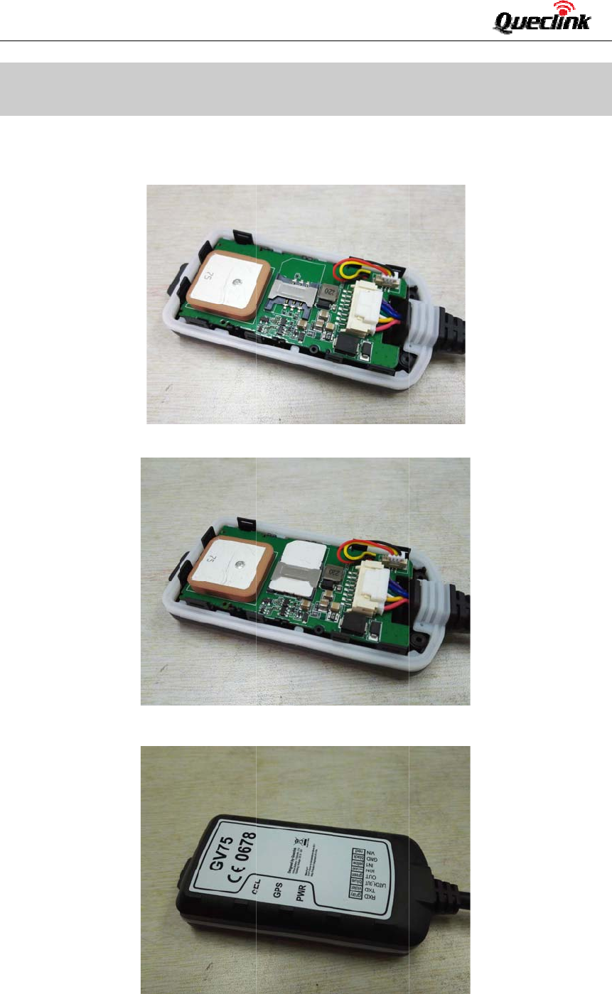
.
InstallaS
I
p
1:Remove
p
2:Insert
t
p
3:Place
t
e
:Makesur
e
sealring.
u
al
0
1
t
arted
I
MCard
thetopcov
e
t
heSIMcard
t
hetopcove
e
thatthes
e
e
r.
intotheSI
M
ronthebot
t
e
alringisin
M
cardholde
t
omcover,
a
placeandt
h
r.
a
ndtightenb
o
h
ereisnoo
b
o
thcoversu
b
viousgapb
ntiltheysn
a
etweencov
e
‐10‐
a
p.
e
rsand
GV
7
TRA
Ste
p
Ste
p
3.2
.
The
‐
Wh
e
run
n
3.3
.
The
dev
i
or2
7
5UserMan
u
CGV75UM0
0
p
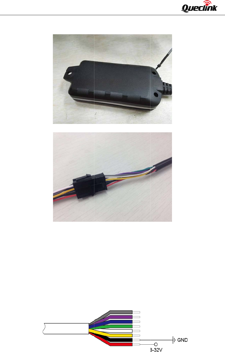
4:Turno
p
5:Conne
c
.
Switchon
methodto
p
‐
Useextern
a
e
ntheexter
n
ing.Wheni
.
PowerCo
n
redwireis
p
i
ceisfrom8
4Vsystems
w
u
al
0
1
verthedevi
c
tthedevice
t
theDevic
e
p
oweronG
V
a
lpowertot
u
nalpoweri
s
nternalbac
k
n
nection
p
owerwire
a
Vto32V.T
h
w
ithoutthe
ceandtight
e
t
oextendca
b
e
V
75:
u
rnon.
s
removed,G
k
upbatteryi
a
ndthebla
c
h
edeviceis
d
needforex
t
Figure2.
e
nthescre
w
b
le.Orcuto
f
V75willswi
sexhausted
,
c
kwireisgr
o
d
esignedto
t
ernaltransf
o
TypicalPow
e
w
withscrew
f
fthe8PinM
o
tchtointer
n
,
GV75will
g
o
undwire.
T
beinstalled
o
rmers.
e
rConnectio
n
cushion.
o
lexconnect
o
n
albackup
b
g
iveareport
T
heinputvo
invehiclest
n
o
r.
b
atteryand
k
andthentu
ltagerange
hatoperate
‐11‐
k
eepon
rnoff.
forthis
on12V
GV
7
TRA
3.4
.
The
igni
t
An
a
onl
y
sign
a
and
3.5
.
The
r
are:
Log
i
Acti
v
Ina
c
The
3.6
.
The
are
pin
con
t
The
The
Lo
g
Ac
t
In
a
7
5UserMan
u
CGV75UM0
0
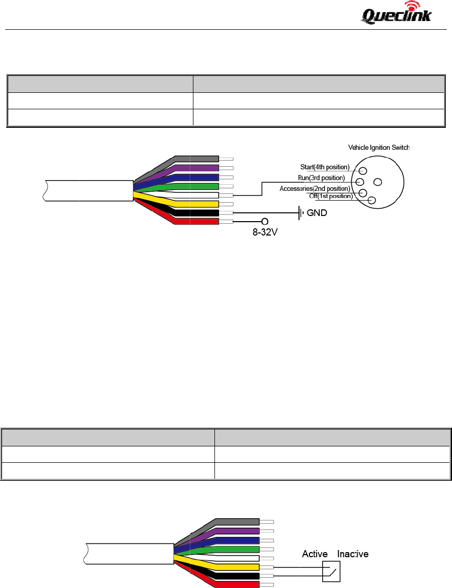
.
IgnitionD
e
whitewire
i
t
ionkeyat“
R
a
lternativet
o
y
availablew
h
a
lcanbeco
n
enterpower
.
DigitalIn
p
r
eisanegat
i
calState
v
e
c
tive
exampleco
n
.
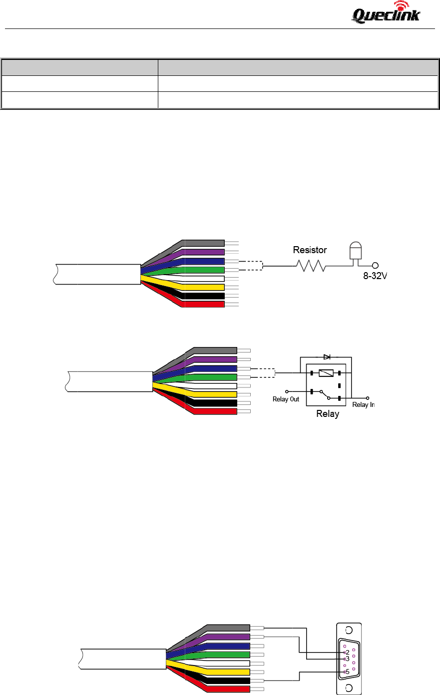
DigitalOu
outputsare
lay.Itmean
s
andanypo
s
t
inuouscurr
e
greenwire
i
electricalc
o
g
icalStatus
t
ive
a
ctive
u
al
0
1
e
tection
Table
i
susedfori
g
R
UN”positio
n
o
connecting
h
enthevehi
c
n
figuredtos
t
savingmod
e
p
ut
ivetriggeri
n
Table6
n
nectionis
s
Figure1:
E
tput
Open‐Drain
t
s
thattheus
e
s
itivevoltag
e
e
ntof0.15
A
i
slowside1
5
o
nditionsar
e
5:Electrical
Figure3.
g
nitiondete
c
n
asshowna
b
totheigniti
o
c
leisrunnin
g
t
arttransmit
t
e
whenigniti
o
n
putonthe
G
:ElectricalC
o
s
howedasf
o
E
xampleof
C
t
ypewithno
e
rhastocon
e
(32Vmax)
A
.
5
0mAmax,
a
e
:
Characteris
t
TypicalIgnit
i
c
tion.Itisst
r
b
ove.
o
nswitchist
g
.Forexampl
t
inginforma
t
o
nisoff.
G
V75.Forne
g
Elect
r
0Vto
1.7V
t
o
nditionsof
o
llows:
C
onnectionf
o
internalpull
‐
nectapull‐u
togenerat
e
a
ndtheblue
Electrical
S
5.0Vto32
V
0Vto3Vo
r
t
icsofIgnitio
n
i
onDetectio
n
r
onglyreco
m
ofindanon
‐
e,thepowe
r
t
iontotheb
a
g
ativetrigg
e
r
icalState
0.8V
t
o32VorO
p
NegativeTri
g
o
rNegative
T
‐
upresistor
w
presistoror
e
acorrect
o
wireislow
s
S
tatus
V
r
open
n
Detection
n
m
mendedto
c
‐
permanent
p
r
sourcefort
a
ckendserve
e
rinputthe
e
p
en
g
gerInputs
T
riggerInpu
w
hichcanal
s
arelaycoil
b
o
utput.Each
s
ide150mA
c
onnectthis
p
owersourc
e
heFMradio
.
rwhenigniti
e
lectricalco
n
ts
s
obeusedto
b
etweenthe
outputcan
maxwithla
t
‐12‐
wireto
e
thatis
.
Ignition
onison
n
ditions
control
output
drivea
t
ch.
GV
7
TRA
Not
e
1.T
do
w
and
Digi
t
Not
e
nee
d
3.7
.
The
r
do
w
Ple
a
and
lev
e
The
asf
o
Log
i
Ena
b
Dis
a
7
5UserMan
u
CGV75UM0
0
e
:
herelayout
p
w
ninsomec
a
backupbatt
e
t
aloutputs
a
e
:Alloutpu
t
d
edwhent
h
.
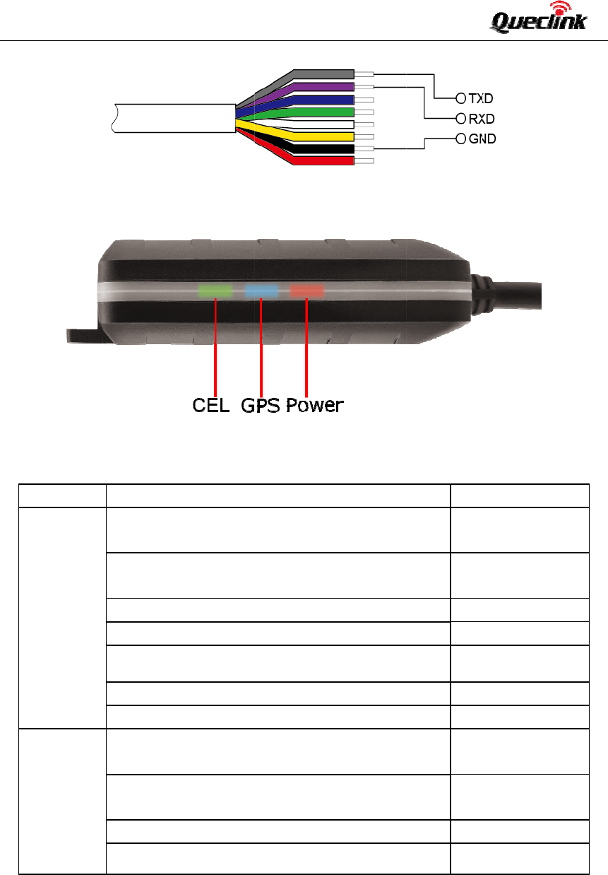
UARTInte
r
eisone
w
nloading,a
n
a
senotethe
‐3Vto‐15V
e
l,while‐3V
t
exampleso
f
o
llows.
i
calState
b
le
a
ble
u
al
0
1
Ta
b
p
utcanbel
a
a
ses,therel
a
e
ryshouldb
e
a
reusedfor
Figur
e
Figure
3
t
sareintern
a
h
eoutputis
c
rface
UARTinter
f
n
dcommuni
UARTinter
f
andthe‐3
V
t
o‐15Vcorr
e
f
connectio
n
Figure
b
le7:Electri
c
a
tchedbyth
a
youtputwi
e
connected.
cutting/rest
o
e
2:TheExa
m
3
:TheExam
a
llypulledu
p
c
onnectedt
o
f
aceonG
V
catingwith
e
f
acesareall
V
to+3Visn
o
e
spondwith
n
sofUART
w
4:TheCon
n
Elec
t
<1.5
V
Ope
n
c
alCondition
esoftware,
s
llnotchang
e
Otherwiset
h
o
ringGND.
T
m
pleofCon
n
pleofConn
e
p
toPWRpi
n
o
aninducti
v
V
75.UART
e
xternaldev
RS232level.
o
tavalidlev
logic1.
w
ithfemale
D
n
ectionofU
A
t
ricalState
V
,drivecurr
e
n
orthepull
‐
sofDigital
O
s
oevenift
h
e
.Touseth
e
h
erelaywill
a
T
heexample
n
ectionto
D
e
ctiontoDr
i
n
byadiode
v
eload.
isusedfo
r
iceslikeCA
N
ForRS232l
e
el.3Vto15
V
D
B‐9andwi
A
RTwithFe
m
e
ntis0.15A
‐
upvoltage(
O
utputs
h
eGV75isr
e
e
latchfuncti
a
lwaysbein
n
sofconnec
t
D
riveanLED
i
veaRelay
.Sonoexte
r
r
configura
t
N
Busmodul
e
e
vel,validsi
V
correspon
d
thexternal
d
m
aleDB‐9
max32V)
e
startedor
p
on,themai
n
n
ormalclose
t
ionsare:
r
nalflyback
d
t
ionandfi
r
e
andRFIDr
e
gnalsare3
V
d
withlogic
0
d
evicesare
s
‐13‐
p
owered
n
power
status.
d
iodeis
r
mware
e
ader.
V
to15V
0
ofTTL
s
howed
GV
7
TRA
3.8
.
Not
e
1‐
C
2‐
con
f
3‐
F
4‐
S
7
5UserMan
u
CGV75UM0
0
.
Indicator
L
e
:
C
ELLEDcann
o
GPSLEDan
f
igurationto
o
F
astflashingi
S
lowflashing
LED
CEL
(Note1)
GPS
(Note2)
PWR
(Note2)
u
al
0
1
Figure5
:
L
ightDescr
i
T
a
o
tbeconfigu
dPWRLED
o
l.
sabout60m
s
isabout60
m
DeviceSta
t
Deviceiss
e
Devicehas
SIMcardn
e
GPSchipis
GPSsends
GPSchipis
GPSchiph
a
Noextern
a
than3.35
V
Noextern
below3.5
5
Externalp
o
Externalp
o
:
TheConne
c
i
ption
F
i
a
ble8:Defin
red.
canbecon
f
s
ON/780ms
m
sON/1940
m
t
us
e
archingGS
M
registeredt
o
e
edspincod
e
poweredof
f
nodataord
a
searchingG
P
a
sgottenGP
S
a
lpowerand
V
.
alpowera
n
5
V.
o
werinand
b
o
werinand
b
c
tionofUA
R
i
gure6:GV7
5
itionofDevi
f
iguredtot
u
OFF.
m
sOFF.
M
network.
o
GSMnetw
o
e
tounlock.
f
.
a
taformate
r
P
Sinfo.
S
info.
backupbatt
e
n
dbackup
b
b
ackupbatte
r
b
ackupbatte
r
R
TwithExte
r
5
LED
c
eStatusan
d
u
rnoffafter
o
rk.
r
roroccurs.
e
ryvoltageis
b
atteryvolt
a
r
yischarging
r
yisfullycha
r
nalDevices
d
LED
aperiodo
f
LED
Fast
(No
t
Slo
w
(No
t
ON
OFF
Slo
w
Fast
ON
lowerOFF
a
geisSlo
w
.Fast
rged.ON
f
timebyu
s
Status
flashing
t
e3)
w
flashing
t
e4)
w
flashing
flashing
w
flashing
flashing
‐14‐
s
ingthe

GV
7
TRA
4.
T
4.1.
T
Tro
u
Aft
e
on,
CEL
qui
c
Me
s
rep
o
bac
GP
R
GV
7
off.
GV
7
suc
c
fixi
n
4.2.
S
7
5UserMan
u
CGV75UM0
0
T
roubles
h
T
roublesho
o
u
ble
e
rGV75istu
LEDalwaysfla
c
kly.
s
sagescan’
t
o
rtedto
kendserve
r
R
S.
7
5doesn’tp
o
7
5can’t
c
essful
n
g.
S
afetyInfo
Please
d
Please
todire
explos
Please
d
u
al
0
1
h
ootinga
n
o
ting
Possi
b
rned
the
shes
TheS
The
s
regis
t
TheS
t
be
the
r
by
TheS
GPRS
.
APN
visitt
TheI
P
serve
o
werThef
u
byAT
get
GPS
The
G
d
onotdisas
s
donotput
t
ctsunlight.
T
ion.
d
onotuse
G
n
dSafety
b
leReason
IMcardisn
o
s
ignalisto
o
t
ertothenet
IMcardisPI
N
IMcardinG
V
.
iswrong.S
heInternet
d
P
addressor
p
riswrong.
u
nctionofp
o
+GTSFR.
G
PSsignalis
w
s
emblethe
d
t
hedevicei
n
T
oohighte
m
G
V75onana
i
Info
o
tinserted.
o
weak;GV
7
work.
N
locked.
V
75doesn’ts
omeAPNs
d
irectly.
p
ortoftheb
a
o
werkeyisd
w
eak.
d
evicebyyo
n
anoverhea
t
m
peraturew
i
rplaneorn
e
Sol
Ple
GV
7
7
5can’tPle
go
o
Us
e
unl
upportTry
cannotAs
k
rig
h
a
ckendMa
ba
c
ad
d
i
sabledEn
a
by
A
Ple
op
e
Iti
fac
e
urself.
t
edortooh
u
illdamaget
h
e
armedical
e
ution
aseinsert
t
7
5.
asemoveG
V
o
dGSMcove
r
e
SIMcard
w
ockSIMPIN.
aGPRSsup
p
k
thenetwo
r
h
tAPN.
kesurethe
c
kendserve
d
ressonthe
I
a
blethefun
c
A
T+GTFKS.
asemoveG
V
e
nsky.
sbetterto
e
thesky.
u
midplace,
a
h
edeviceor
e
quipment.
t
heSIMca
r
V
75intoplac
e
rage.
w
ithoutSIM
p
ortingSIMc
a
r
koperator
IPaddress
risanid
e
I
nternet.
ctionofpo
w
V
75toapla
c
letthetop
a
ndavoide
x
evencause
‐15‐
r
dinto
e
swith
PIN,or
a
rd.
forthe
forthe
e
ntified
w
erkey
c
ewith
surface
x
posure
battery

GV
7
TRA
5.
F
Thi
s
Op
e
inte
r
ma
y
TH
E
CA
U
MO
D
EQ
U
Thi
s
pur
s
aga
i
radi
a
ma
y
inte
r
inte
r
off
a
foll
o
-- R
e
-- In
-- C
con
n
-- C
o
RF
e
Thi
s
env
i
7
5UserMan
u
CGV75UM0
0
F
CCNOTE
s
device co
m
e
ration is su
r
ference, an
d
y
cause und
e
E
MANUFA
C
U
SED BY U
N
D
IFICATIO
N
U
IPMENT.
s
equipment
s
uant to part
i
nst harmful
a
te radio fre
q
y
cause har
m
r
ference wil
l
r
ference to
r
a
nd on, the
o
wing measu
e
orient or re
crease the
s
onnect the
e
n
ected.
o
nsult the d
e
e
xposure st
a
s
equipmen
t
i
ronment .T
h
u
al
0
1
:
m
plies with P
a
bject to the
d
(2) this de
v
e
sired opera
t
C
TURER IS
N
AUTHORI
Z
N
S OR CHA
N
has been te
15 of the F
C
interference
q
uency ene
r
m
ful interfer
e
l
not occur
r
adio or tele
v
user is en
c
res:
locate the r
e
s
eparation b
e
e
quipment i
n
e
aler or an e
x
a
temen
t
t
complies
w
h
e device h
a
a
rt 15 of the
following t
w
v
ice must ac
c
t
ion.
NOT RESP
Z
ED MODIFI
N
GE COUL
D
sted and fo
u
C
C Rules. T
h
in a residen
t
r
gy and, if n
o
e
nce to radi
o
in a partic
u
v
ision recep
t
c
ouraged to
e
ceiving ante
e
tween the
e
n
to an outle
t
x
perienced
r
w
ith FCC r
a
a
s been ev
a
FCC Rules.
w
o conditio
n
c
ept any inte
r
ONSIBLE F
CATIONS
O
D
VOID TH
E
u
nd to compl
h
ese limits a
r
t
ial installati
o
o
t installed a
o
communic
a
u
lar installati
t
ion, which
c
try to corr
e
nna.
e
quipment a
n
t
on a circui
t
r
adio/TV tec
h
a
diation ex
p
a
luated to m
e
n
s: (1) this
d
r
ference rec
e
OR ANY R
A
O
R CHANG
E
E
USER’S A
U
y with the li
m
r
e designed
t
o
n. This equ
i
nd used in
a
a
tions. How
e
on. If this
e
an be deter
m
e
ct the inter
f
n
d receiver.
t
different fr
o
h
nician for h
e
p
osure limit
s
e
et general
d
evice may
e
ived, includ
A
DIO OR T
V
E
TO THIS E
U
THORITY
T
m
its for a Cl
a
t
o provide re
i
pment gene
a
ccordance
w
e
ver, there i
s
e
quipment d
m
ined by tu
r
f
erence by
o
o
m that to
w
e
lp.
s
set forth
f
RF exposu
r
not cause
ing interfere
n
V
INTERFE
R
QUIPMENT
T
O OPERA
T
a
ss B digital
asonable pr
o
rates, uses
a
w
ith the instr
u
s
no guaran
t
oes cause
r
ning the eq
u
o
ne or mor
e
w
hich the re
c
f
or an unc
o
r
e requirem
e
‐16‐
harmful
n
ce that
R
ENCE
. SUCH
T
E THE
device,
o
tection
a
nd can
u
ctions,
t
ee that
harmful
u
ipment
e
of the
c
eiver is
o
ntrolled
e
nt.
a separation distance of 20 cm maintained between the antenna of this device and persons during operation.
To ensure compliance, operation at closer than this distance is not recommended.