Queclink Wireless Solutions GV75W WCDMA/GSM/GPRS/GPS Locator User Manual YQD GV75W
Queclink Wireless Solutions Co.,Ltd WCDMA/GSM/GPRS/GPS Locator YQD GV75W
User Manual

GV75WUserManual
TRACGV75WUM001
‐0‐
GV75WUserManual
WCDMA/GSM/GPRS/GPSTracker
TRACGV75WUM001
Version:R1.00
GV75WUserManual
TRACGV75WUM001
‐1‐
DocumentTitle GV75WUserManual
Version 1.00
Date 2016‐09‐09
Status Release
DocumentControlID TRACGV75WUM001
GeneralNotes
Queclinkoffersthisinformationasaservicetoitscustomers,tosupportapplicationandengineering
efforts that use the products designed by Queclink. The information provided is based upon
requirementsspecificallyprovidedtoQueclinkbythecustomers.Queclinkhasnotundertakenany
independentsearchforadditionalrelevantinformation,includinganyinformationthatmaybeinthe
customer’spossession.Furthermore,systemvalidationofthisproductdesignedbyQueclinkwithina
larger electronic system remains the responsibility of the customer or the customer’s system
integrator.Allspecificationssuppliedhereinaresubjecttochange.
Copyright
ThisdocumentcontainsproprietarytechnicalinformationwhichisthepropertyofQueclinkWireless
SolutionsCo.,Ltd.Thecopyingofthisdocument,distributiontoothers,andcommunicationofthe
contentsthereof,areforbiddenwithoutexpressauthority.Offendersareliabletothepaymentof
damages.Allrightsarereservedintheeventofapatentgrantorregistrationofautilitymodelor
design.Allspecificationssuppliedhereinaresubjecttochangewithoutnoticeatanytime.

GV75WUserManual
TRACGV75WUM001
‐2‐
Contents
Contents............................................................................................................................................‐2‐
TableIndex........................................................................................................................................‐3‐
FigureIndex.......................................................................................................................................‐4‐
0.RevisionHistory.............................................................................................................................‐5‐
1.Introduction..................................................................................................................................‐6‐
1.1.Reference...........................................................................................................................‐6‐
1.2.TermsandAbbreviations....................................................................................................‐6‐
2.ProductOverview..........................................................................................................................‐7‐
2.1.Appearance........................................................................................................................‐7‐
2.2.PartsList.............................................................................................................................‐7‐
2.3.InterfaceDefinition............................................................................................................‐8‐
3.GettingStarted..............................................................................................................................‐9‐
3.1.InstallaSIMCard................................................................................................................‐9‐
3.2.SwitchontheDevice........................................................................................................‐10‐
3.3.PowerConnection............................................................................................................‐10‐
3.4.IgnitionDetection.............................................................................................................‐11‐
3.5.DigitalInput......................................................................................................................‐11‐
3.6.DigitalOutput...................................................................................................................‐12‐
3.7.UARTInterface.................................................................................................................‐13‐
3.8.USBInterface....................................................................................................................‐13‐
3.9.IndicatorLightDescription...............................................................................................‐13‐
4.TroubleshootingandSafetyInfo.................................................................................................‐15‐
4.1.Troubleshooting...............................................................................................................‐15‐
4.2.SafetyInfo........................................................................................................................‐15‐

GV75WUserManual
TRACGV75WUM001
‐3‐
TableIndex
TABLE1:REFERENCE........................................................................................................................‐6‐
TABLE2:TERMSANDABBREVIATIONS.............................................................................................‐6‐
TABLE3:PARTSLIST..........................................................................................................................‐7‐
TABLE4:DESCRIPTIONOFGV75WINTERFACE.................................................................................‐8‐
TABLE5:DESCRIPTIONOFGV75WEXTENSIONCABLE.....................................................................‐8‐
TABLE6:ELECTRICALCHARACTERISTICSOFIGNITIONDETECTION.............................................…‐11‐
TABLE7:ELECTRICALCONDITIONSOFNEGATIVETRIGGERINPUTS..............................................‐11‐
TABLE8:ELECTRICALCONDITIONSOFDIGITALOUTPUTS..............................................................‐12‐
TABLE9:DEFINITIONOFDEVICESTATUSANDLED........................................................................‐14‐

GV75WUserManual
TRACGV75WUM001
‐4‐
FigureIndex
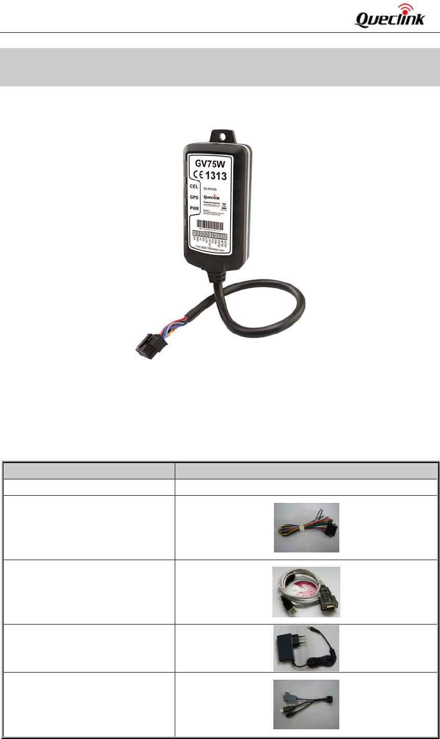
FIGURE1:APPEARANCEOFGV75W.................................................................................................‐7‐
FIGURE2:TYPICALPOWERCONNECTION......................................................................................‐11‐
FIGURE3:TYPICALIGNITIONDETECTION.......................................................................................‐11‐
FIGURE4:CONNECTIONFORNEGATIVETRIGGERINPUTS.............................................................‐11‐
FIGURE5:CONNECTIONTODRIVEANLED.....................................................................................‐12‐
FIGURE6:CONNECTIONTODRIVEARELAY...................................................................................‐12‐
FIGURE7:THECONNECTIONOFUARTWITHFEMALEDB‐9..........................................................‐13‐
FIGURE8:THECONNECTIONOFUARTWITHEXTERNALDEVICES.................................................‐13‐
FIGURE9:GV75WLED....................................................................................................................‐13‐

GV75WUserManual
TRACGV75WUM001
‐5‐
0. RevisionHistory
Revision Date Author DescriptionofChange
1.00 2016‐09‐09 Super Zhao Initial
GV75WUserManual
TRACGV75WUM001
‐6‐
1. Introduction
TheGV75WisacompactwaterproofGPStrackerdesignedforawide variety of vehicle tracking
applications.It hasmultiple I/O interfacesthatcan be used formonitoring or controllingexternal
devices. Its built‐in GPS receiver has superior sensitivity and fast time to first fix. Its triple band
WCDMAsubsystemsupportsUMTS/HSDPA850(BandV)/1900(BandII)/2100(BandI)MHzandquad
bandGSM/GPRS850/900/1800/1900MHz,allowingtheGV75W'slocationtobemonitoredinreal
timeorperiodicallytrackedbyabackendserverandmobiledevices.Itsbuilt‐in3‐axisaccelerometer
allows motion detection and extends battery life through sophisticated power management
algorithms.Systemintegrationisstraightforwardascompletedocumentationisprovidedforthefull
featured @Track protocol. The @Track protocol supports a wide variety of reports including
emergency,geo‐fenceboundarycrossings,drivingbehavior,lowbatteryandscheduledGPSfix.
1.1. Reference
SN DocumentName Remark
[1] GV75W@TrackAirInterfaceProtocol The air protocol interface between
GV75Wandbackendserver.
[2] @TrackAirInterface
f
or Garmin‐FMI
Protocol
Table1:Reference
1.2. TermsandAbbreviations
Abbreviation Description
DIN DigitalInput
DOUT DigitalOutput
GND Ground
LATCH_OUT LatchedDigitalOutputs
IGN Ignition
USB_VBUS USBpowerconnector
USB_DM USBdigitalnegative
USB_DP USBdigitalpositive
RXD ReceiveData
TXD TransmitData
Table2:TermsandAbbreviations
GV75WUserManual
TRACGV75WUM001
‐7‐
2. ProductOverview
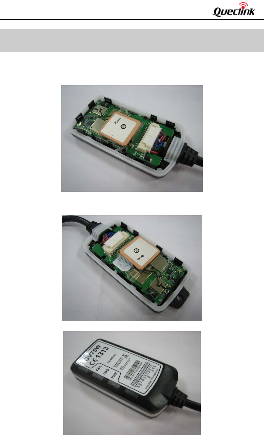
2.1. Appearance
Figure1:AppearanceofGV75W
2.2. PartsList
Table3:PartsList
Name Picture
GV75WTracker 102mm*46mm*20.5mm
GV75WExtensionCable
USB‐232Cable(optional)
12VDCSupply(optional)
GV75W_UART_USB_PWR_Convert_
CABLE(optional)
GV75WUserManual
TRACGV75WUM001
‐8‐
2.3. InterfaceDefinition
GV75Whas11interfaceswhichincludetheconnectionforpower,ignitioninput,digitalinput,digital
output,USB,TXDandRXD,etc.Theusercableinfoisshowninthefollowingtable.
Table4:DescriptionofGV75WInterface
Table5:DescriptionofGV75WExtensionCable
Index Colour Description Comment
1 Red Power ExternalDCpowerinput,8‐32V
2 Black Ground Systemground(connectedtothevehicle’sframedirectly)
3 Yellow Digitalinput Digitalinput,negativetrigger
4 White Ignition Ignitioninput,positivetrigger
5 Green Digitaloutput2 Digitaloutput,lowside150mAmax
6 Blue Digitaloutput1 Digitaloutput,lowside150mAmaxwithlatch
7 Purple TXD UARTTXD,RS232
8 Gray RXD UARTRXD,RS232
9 Orange USB_VBUS USBpowerconnector
10 Brown USB_DM USBdigitalnegative
11 Pink RXD_DP USBdigitalpositive
Index Colour Description Comment
1 Red Power ExternalDCpowerinput,8‐32V
2 Black Ground Systemground(connectedtothevehicle’sframedirectly)
3 Yellow Digitalinput Digitalinput,negativetrigger
4 White Ignition Ignitioninput,positivetrigger
5 Green Digitaloutput2 Digitaloutput,lowside150mAmax
6 Blue Digitaloutput1 Digitaloutput,lowside150mAmaxwithlatch
7 Purple TXD UARTTXD,RS232
8 GrayRXD UARTRXD,RS232
GV75WUserManual
TRACGV75WUM001
‐9‐
3. GettingStarted
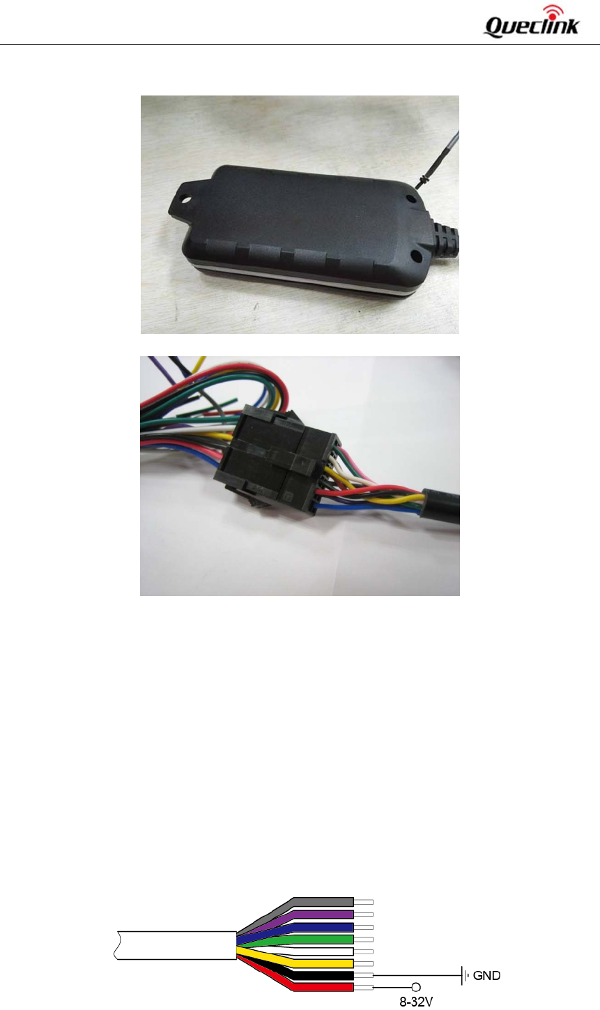
3.1. InstallaSIMCard
Step1:Removethetopcover.
Step2:InserttheSIMcardintotheSIMcardholder.Note:PressdownontheSIMcardslightly
tomakeitslideintotheslot.
Step3:Placethetopcoveronthebottomcover,andtightenbothcoversuntiltheysnap.
Note:Makesurethatthesealringisinplaceandthereisnoobviousgapbetweencoversand
sealring.
GV75WUserManual
TRACGV75WUM001
‐10‐
Step4:Turnoverthedeviceandtightenthescrewwithscrewcushion.
Step5:Connectthedevicetoextensioncableorcutoffthe12PinMolexconnector.
3.2. SwitchontheDevice
The method to power on GV75W:Useexternalpowertoturnon.
Whentheexternalpowerisremoved,GV75Wwillswitchtointernal backupbattery andkeep on
running.Wheninternalbackupbatteryisexhausted,GV75Wwillreportamessageandthenturnoff.
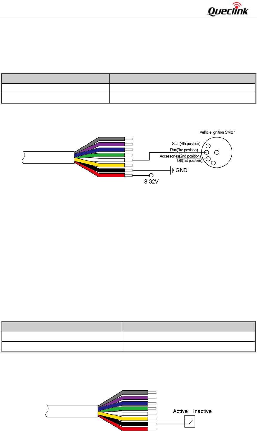
3.3. PowerConnection
Theredwireispowerwireandtheblackwireisgroundwire.Theinputvoltagerangeforthisdevice
isfrom8Vto32V.Thedeviceisdesignedtobeinstalledinvehicles that operate on 12V or 24V
systemswithouttheneedforexternaltransformers.
GV75WUserManual
TRACGV75WUM001
‐11‐
Figure2:TypicalPowerConnection
3.4. IgnitionDetection
Table6:ElectricalCharacteristicsofIgnitionDetection
Figure3:TypicalIgnitionDetection
The white wire is used for ignition detection. It is strongly recommended to connect this wire to
ignitionkeyat“RUN”positionasshownabove.
Analternativetoconnectingtotheignitionswitchistofindanon‐permanentpowersource(likethe
powersourceforFMradio)thatisonlyavailablewhenthevehicleisrunning.Ignitionsignalcanbe
configuredtostarttransmittinginformationtothebackendserverwhenignitionisonandtoenter
powersavingmodewhenignitionisoff.
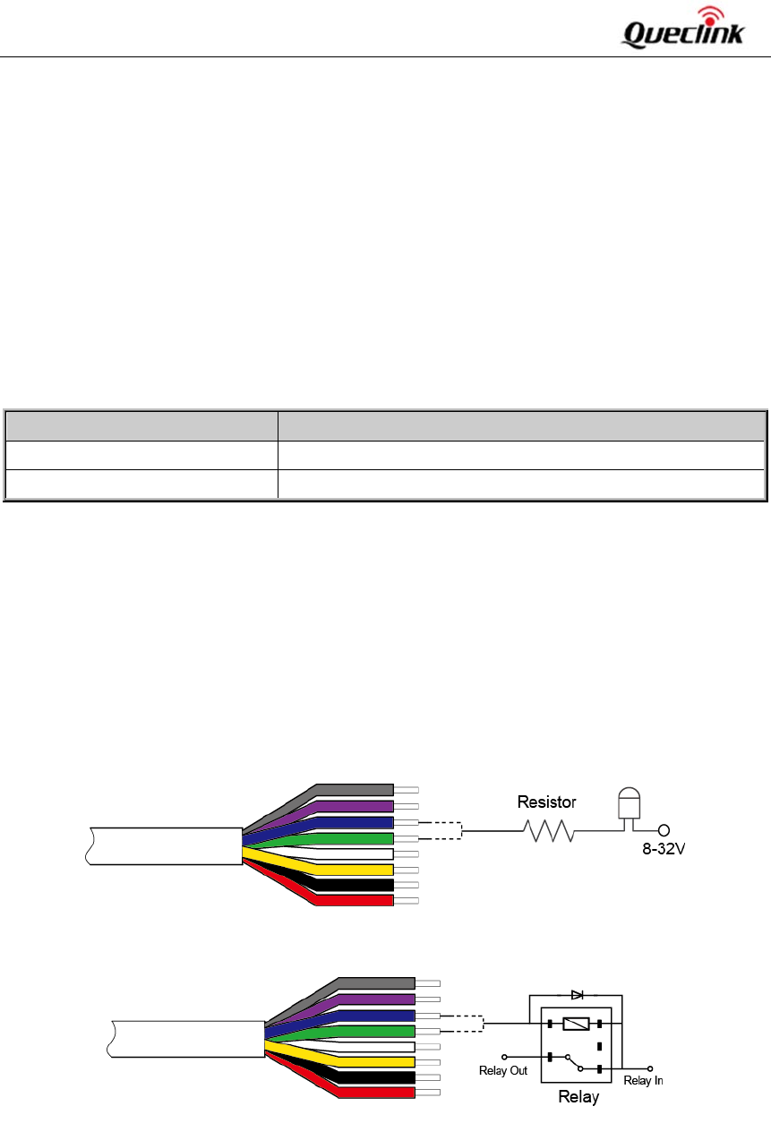
3.5. DigitalInput
ThereisanegativetriggerinputonGV75W.Fornegativetriggerinput,theelectricalconditionsare
asfollows:
LogicalState ElectricalState
Active 0Vto0.8V
Inactive 1.7Vto32VorOpen
Table7:ElectricalConditionsofNegativeTriggerInputs
Theconnectionisshownasfollows:
Figure4:ConnectionforNegativeTriggerInputs
LogicalStatus ElectricalStatus
Active 5.0Vto32V
Inactive 0Vto3Voropen
GV75WUserManual
TRACGV75WUM001
‐12‐
3.6. DigitalOutput
TheoutputsareOpen‐Draintypewithnointernalpull‐upresistorwhichcanbeusedtocontrolarelay.
Itmeansthattheuserhastoconnectapull‐upresistororarelaycoilbetweentheoutputpinand
any positive voltage (32V max) to generate correct output. Eachoutputcandriveacontinuous
currentof0.15A.
Thegreenwireislowside150mAmax,andthebluewireislowside150mAmaxwithlatch.
Theelectricalconditionsareshowninthefollowingtable:
Table8:ElectricalConditionsofDigitalOutputs
Note:
Therelayoutputcanbelatchedbythesoftware,soeveniftheGV75Wisrestartedorpowereddown
insomecases,therelayoutputwillnotchange.Tousethelatchfunction,themainpowerandbackup
batteryshouldbeconnected.Otherwisetherelaywillalwaysbeinnormallyclosedstate.
Digitaloutputsareusedforcutting/restoringGND.Theconnectionsareshownbelow.
Figure5:ConnectiontoDriveanLED
Figure6:ConnectiontoDriveaRelay
Note: All outputs are internally pulled up to PWR pin by a diode. Sonoexternalflybackdiodeis
neededwhentheoutputisconnectedtoaninductiveload.
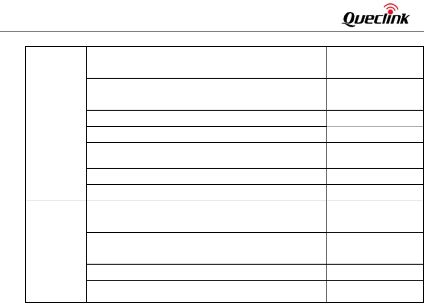
LogicalState ElectricalState
Enable <1.5V,drivecurrentis0.15A
Disable Openorthepull‐upvoltage(max32V)
GV75WUserManual
TRACGV75WUM001
‐13‐
3.7. UARTInterface
ThereisoneUARTinterface on GV75W. UART isusedforconfiguration, firmware download, and
communicatingwithexternaldevicessuchasCANBusmoduleandRFIDreader.
PleasenotetheUARTinterfacesareallRS232level.ForRS232level,validsignalsare3Vto15Vand‐
3Vto‐15V,andthe‐3Vto+3Visnotavalidlevel.3Vto15Vcorrespondswithlogic0ofTTLlevel,
while‐3Vto‐15Vcorrespondswithlogic1.
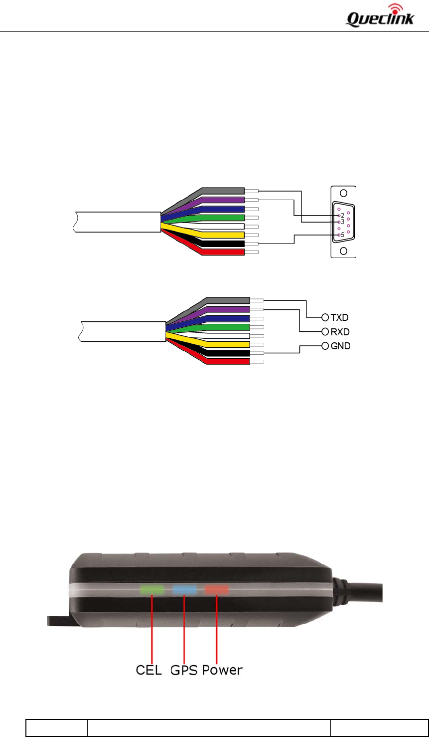
The examples of connections of UART with female DB‐9 and with external devices are shown as
follows.
Figure7:TheConnectionofUARTwithFemaleDB‐9
Figure8:TheConnectionofUARTwithExternalDevices
3.8.
USBInterface
Gv75WhasoneUSBinterfacewhichisusedforfirmware download and connects to the
GV75W_UART_USB_PWR_Convert_CABLE(optional).TheGV75W_UART_USB_PWR_Convert_CABLE
isusedwhendownloadingthefirmware.
3.9. IndicatorLightDescription
Figure9:GV75WLED
LED DeviceStatus LEDStatus
GV75WUserManual
TRACGV75WUM001
‐14‐
CEL
(Note1)
DeviceissearchingGSMnetwork. Fastflashing
(Note3)
DevicehasregisteredtoGSMnetwork. Slowflashing
(Note4)
SIMcardneedspincodetounlock. ON
GPS
(Note2)
GPSchipispoweredoff. OFF
GPSsendsnodataordataformaterroroccurs. Slowflashing
GPSchipissearchingGPSinfo. Fastflashing
GPSchiphasgottenGPSinfo. ON
PWR
(Note2)
Noexternalpowerandbackupbatteryvoltageislower
than3.35V.
OFF
Noexternalpowerandbackupbatteryvoltageisbelow
3.55V.
Slowflashing
Externalpowerinandbackupbatteryischarging. Fastflashing
Externalpowerinandbackupbatteryisfullycharged. ON
Table9:DefinitionofDeviceStatusandLED
Note:
1‐CELLEDcannotbeconfigured.
2 ‐ GPS LED and PWR LED can be configured to turn off after a periodoftimebyusingthe
configurationtool.
3‐Fastflashingisabout60msON/780msOFF.
4‐Slowflashingisabout60msON/1940msOFF.
GV75WUserManual
TRACGV75WUM001
‐15‐
4. TroubleshootingandSafetyInfo
4.1. Troubleshooting
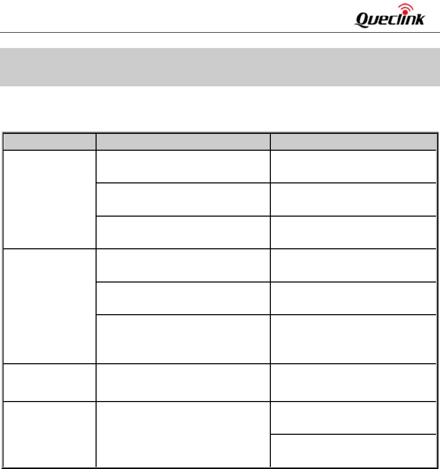
Trouble PossibleReason Solution
After GV75W is
turnedon,theCEL
LEDalwaysflashes
quickly.
TheSIMcardisnotinserted. Please insert the SIM card into
GV75W.
Thesignalistooweak;GV75Wcan’t
registertothenetwork.
PleasemoveGV75Wintoplaces
withgoodGSMcoverage.
TheSIMcardisPINlocked. Use SIM card without SIM PIN, or
unlockSIMPIN.
Messages can’t be
reported to the
backend server by
GPRS.
TheSIMcardinGV75Wdoesn’t
supportGPRS.
TryaGPRSsupportingSIMcard.
APNiswrong.SomeAPNscannotvisit
theInternetdirectly.
Ask the network operator for the
rightAPN.
TheIPaddressorportofthebackend
serveriswrong.
Make sure the IP address for the
backend server is an identified
addressontheInternet.
GV75W doesn’t
poweroff.
Thefunctionofpowerkeyisdisabled
byAT+GTSFR.
Enablethefunctionofpowerkeyby
AT+GTFKS.
GV75Wcan’tget
successfulGPSfix.
TheGPSsignalisweak. PleasemoveGV75Wtoaplacewith
opensky.
Itisbettertoletthetopsurfaceface
thesky.
4.2. SafetyInfo
Pleasedonotdisassemblethedevicebyyourself.
Pleasedonotputthedeviceinanoverheatedortoohumidplace,andavoidexposureto
direct sunlight. Too high temperature will damage the device or even cause battery
explosion.
PleasedonotuseGV75Wonanairplaneornearmedicalequipment.
WARNING:
Thisdevicecomplieswithpart15oftheFCCRules.Operationissubjecttothefollowingtwo
conditions:
Thisdevicemaynotcauseharmfulinterference,and
Thisdevicemustacceptanyinterferencereceived,includinginterferencethatmaycause
undesired operation.Changes or modifications not expressly approved by the party
responsibleforcompliancecouldvoidtheuser’sauthoritytooperatetheequipment.

GV75WUserManual
TRACGV75WUM001
‐16‐
NOTE:
ThisequipmenthasbeentestedandfoundtocomplywiththelimitsforaClassBdigital
device, pursuant to part 15 of the FCC Rules. These limits are designed to provide
reasonableprotectionagainstharmfulinterferenceinaresidentialinstallation.
Thisequipmentgenerates,usesandcanradiateradiofrequencyenergyand,ifnotinstalled
and used in accordance with the instructions, may cause harmful interference to radio
communications. However, there is no guarantee that interference will not occur in a
particular installation. If this equipment does cause harmful interference to radio or
televisionreception,whichcanbedeterminedbyturningtheequipmentoffandon,the
userisencouragedtotrytocorrecttheinterferencebyoneormoreofthefollowing
measures:
‐Reorientorrelocatethereceivingantenna.
‐Increasetheseparationbetweentheequipmentandreceiver.
‐Connecttheequipmentintoanoutletonacircuitdifferentfromthattowhichthereceiver
isconnected.
‐Consultthedealeroranexperiencedradio/TVtechnicianforhelp.
RFExposureStatement:
Fortheproduct,undernormaluseconditionisatleast20cmawayfromthebodyofthe
user,theusermustkeepingatleast20cmdistancetotheproduct.