Quectel Wireless Solutions 16182009003 GPS Module User Manual L10
Quectel Wireless Solutions Company Limited GPS Module L10
User Manual
L10
Quectel GPS Engine
L10 User Guide
L10_User _Guide_V1.00

Document Title L10 User Guide
Version 1.00
Date 2009-7-25
Status Release
Document Control ID L10_User_Guide_V1.00
General Notes
Quectel offers this information as a service to its customers, to support application and
engineering efforts that use the products designed by Quectel. The information provided is
based upon requirements specifically provided to Quectel by the customers. Quectel has not
undertaken any independent search for additional relevant information, including any
information that may be in the customer’s possession. Furthermore, system validation of this
product designed by Quectel within a larger electronic system remains the responsibility of
the customer or the customer’s system integrator. All specifications supplied herein are
subject to change.
Copyright
This document contains proprietary technical information which is the property of Quectel
Limited., copying of this document and giving it to others and the using or communication of
the contents thereof, are forbidden without express authority. Offenders are liable to the
payment of damages. All rights reserved in the event of grant of a patent or the registration of
a utility model or design. All specification supplied herein are subject to change without
notice at any time.
Copyright © Shanghai Quectel Wireless Solutions Co., Ltd. 2009
L10_User_Guide_V1.00 - 1 -

Contents
Quectel GPS Engine........................................................................................................................0
L10 User Guide................................................................................................................................0
L10_User _Guide_V1.00.................................................................................................................0
Contents ............................................................................................................................................2
1. EVB Kit Introduction....................................................................................................................3
1.1 EVB Top and Bottom View...........................................................................................3
1.2 EVB Accessories...........................................................................................................5
1.3 EVB and Accessories....................................................................................................6
2. Operational description.................................................................................................................6
2.1 Tune on the module..............................................................................................................6
2.2. L10 features.........................................................................................................................7
2.2.1 General specification..................................................................................................7
2.2.2 Hardware Specification ..............................................................................................8
2.2.3 Software and other specifications...............................................................................8
2.2.4 Solution of L10...........................................................................................................9
3. GPS Protocol............................................................................................................................12
4. Compliance with FCC Regulations.........................................................................................12
L10_User_Guide_V1.00 - 2 -
1. EVB Kit Introduction
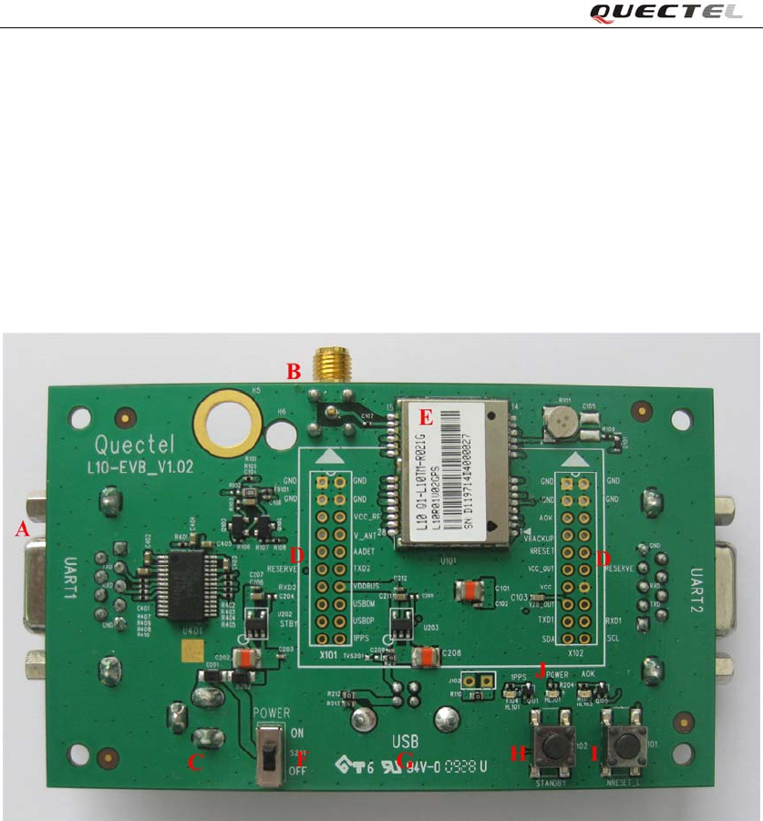
1.1 EVB Top and Bottom View
EVB top view
L10_User_Guide_V1.00 - 3 -
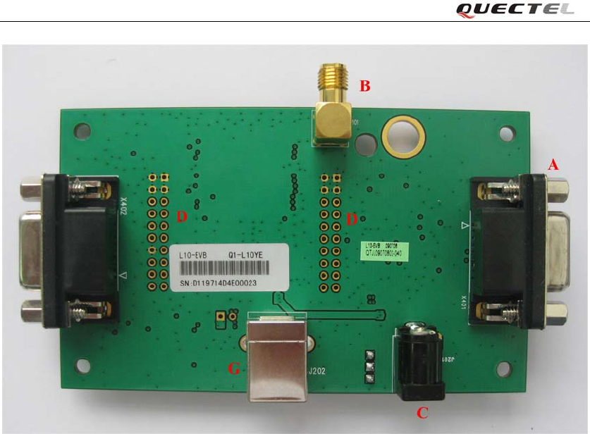
EVB bottom view
A: UART port
B: Antenna interface
C: Adapter interface
D: Test points
E: L10 Module
F: POWER switch
G: USB interface
H: STANDBY button
I: RESET button
J: Indication LEDs
L10_User_Guide_V1.00 - 4 -
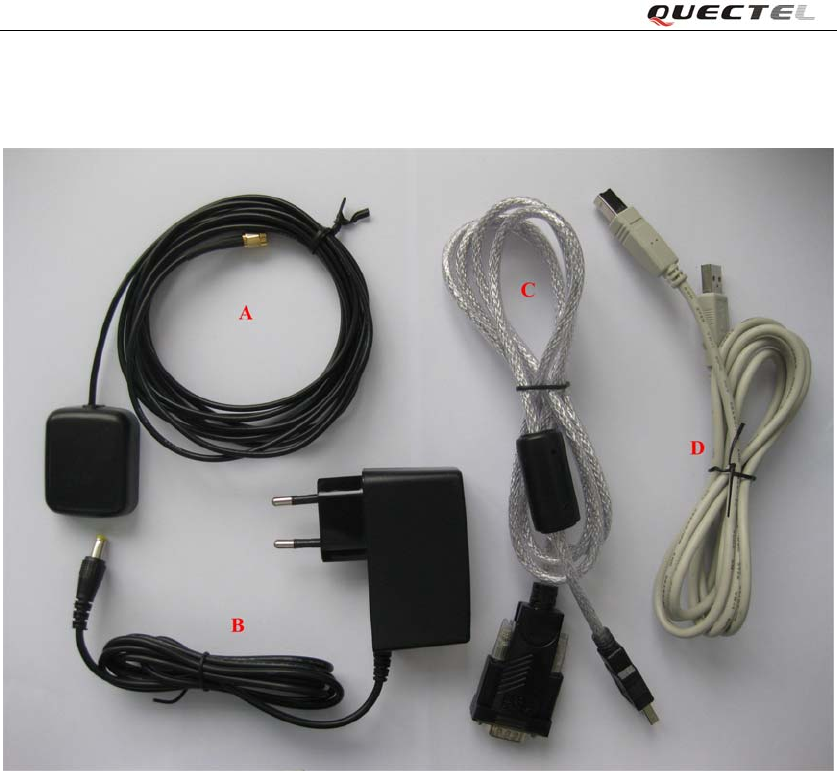
1.2 EVB Accessories
EVB accessories
A: GPS active antenna (3.3V)
B: DC5V/2A power adapter
C: Serial port cable (USB 2.0)
D: USB cable
L10_User_Guide_V1.00 - 5 -
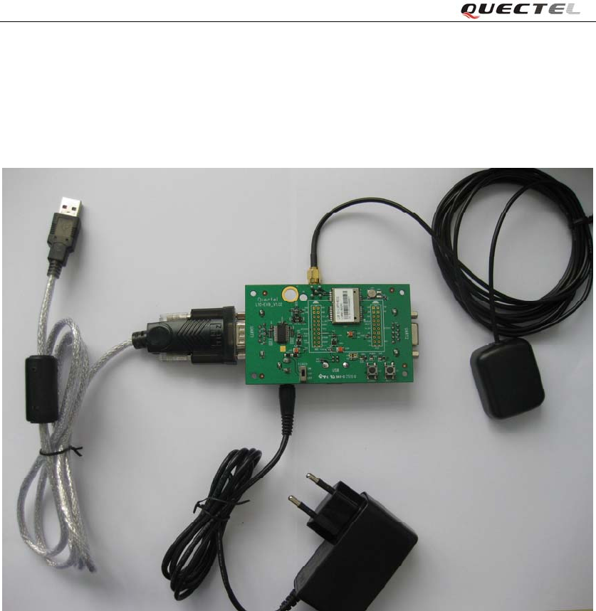
1.3 EVB and Accessories
When USB to RS232 cable is used, the EVB and its accessories are equipped as shown in Figure
12.
EVB and accessory equipments with serial cable
2. Operational description
2.1 Tune on the module
L10_User_Guide_V1.00 - 6 -
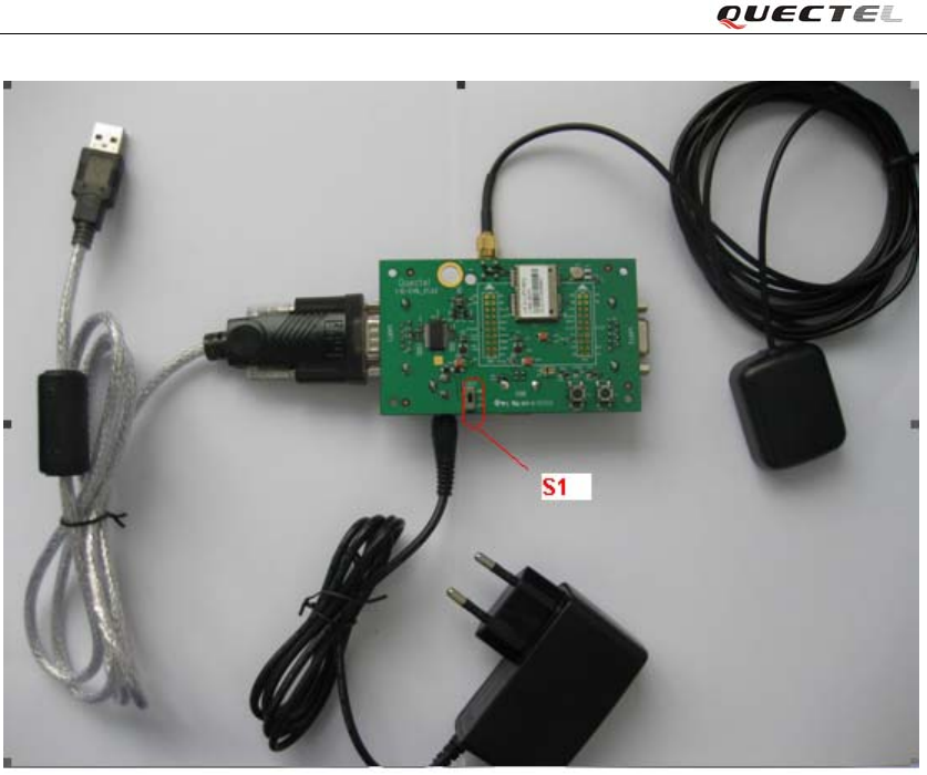
switching the “S1” switch to ON state; and the module is tuning on successfully.
2.2. L10 features
2.2.1 General specification
The L10 GPS module brings the high performance of the MTK positioning engine to
the industrial standard. The module supports 210 PRN channels. With 66 search
channels and 22 simultaneous tracking channels, it acquires and tracks satellites in
the shortest time even at indoor signal level. This versatile, stand-alone receiver
combines an extensive array of features with flexible connectivity options. The
embedded FLASH memory provides capacity for storing user-specific configuration
settings and allows for future updates. L10 advanced jamming suppression
mechanism and innovative RF architecture provides a high level of immunity for
jamming, ensuring maximum GPS performance.
L10_User_Guide_V1.00 - 7 -

The L10 is an SMD type module with the compact 22.4mm x 17.0mm x 3.0 mm form
factor, which can be embedded in customer applications through the 28-pin pads. It
provides all hardware interfaces between the module and customer’s board.
z The UART port can help to develop customer’s application easily.
z The USB port is available for faster data transmission and more flexibility
z The antenna interface supports passive and active antenna.
2.2.2 Hardware Specification
The L10 GPS module brings the high performance of the MTK positioning engine to the
industrial standard. The module supports 210 PRN channels. With 66 search channels and 22
simultaneous tracking channels, it acquires and tracks satellites in the shortest time even at indoor
signal level. This versatile, stand-alone receiver combines an extensive array of features with
flexible connectivity options. The embedded FLASH memory provides capacity for storing
user-specific configuration settings and allows for future updates. L10 advanced jamming
suppression mechanism and innovative RF architecture provides a high level of immunity for
jamming, ensuring maximum GPS performance. The module supports location, navigation and
industrial applications including autonomous GPS C/A, SBAS (including WAAS, EGNOS,
MSAS), DGPS (RTCM), and AGPS.
The L10 is an SMD type module with the compact 22.4mm x 17.0mm x 3.0 mm form factor,
which can be embedded in customer applications through the 28-pin pads. It provides all hardware
interfaces between the module and customer’s board.
z The UART port can help to develop customer’s application easily.
z The USB port is available for faster data transmission and more flexibility
z The antenna interface supports passive and active antenna.
The PCB of M10 is 4 layers.
2.2.3 Software and other specifications
Feature Implementation
Power supply Single supply voltage: 3.0V – 4.3V typical : 3.3V
Power consumption
(passive antenna)
z Acquisition 43mA
z Tracking 38mA
z Standby TBD
Receiver Type z GPS L1 1575.42MHz C/A Code
z 66 search channels, 22 simultaneous tracking channels
Sensitivity z Cold Start (Autonomous) -147 dBm
L10_User_Guide_V1.00 - 8 -

z Reacquisition -160 dBm
z Hot start -160 dBm
z Tracking -165 dBm
Time-To-First-Fix
z Cold Start (Autonomous) 35s average
z Warm Start (Autonomous) 35s average
z Hot Start (Autonomous) <1.2 s
z EPO, BEE 5 ~10s
z SUPL 5 ~10s
Position Accuracy z Without Aid 3.0 m 2D-RMS
z DGPS 2.5 m
Max Update Rate z 10Hz
Accuracy of 1PPS Signal z Typical accuracy 61 ns
z Time pulse adjustable from 1ms to 999ms, default 100ms
Velocity Accuracy z Without Aid 0.1 m/s
z DGPS 0.05 m/s
Acceleration Accuracy z Without Aid 0.1 m/s²
z DGPS 0.05 m/s²
Dynamic Performance z Maximum Altitude 18,000 m
z Maximum Velocity 515 m/s Maximum
z Acceleration 4 G
UART Port z UART Port: two lines TXD1 and RXD1
z Supports baud rate from 4800bps to 115200bps.
z UART Port is used for NMEA outputting or inputting , PMTK
private messages inputting and firmware upgrade
USB Port z Support USB 2.0 full-speed compatible
z USB Port is used for NMEA outputting or inputting , PMTK
private messages inputting and firmware upgrade
Temperature range
z Normal operation: -40°C ~ +85°C
z Storage temperature: -45°C ~ +125°C
Physical Characteristics Size:
22.4±0.15 x 17±0.15 x 3.0±0.1mm
Weight: about 2.2g
Firmware Upgrade Firmware upgrade over UART port or USB port
2.2.4 Solution of L10
The hardware solution is MT3329; The software solution is MTK Release GPS AXN.
MT3329
L10_User_Guide_V1.00 - 9 -
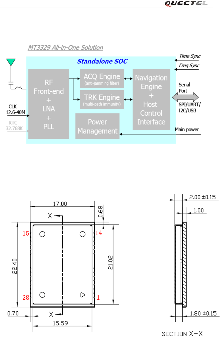
2.2.5 Mechanical architecture
L10 Top view and Side dimensions(Unit:mm)
L10_User_Guide_V1.00 - 10 -
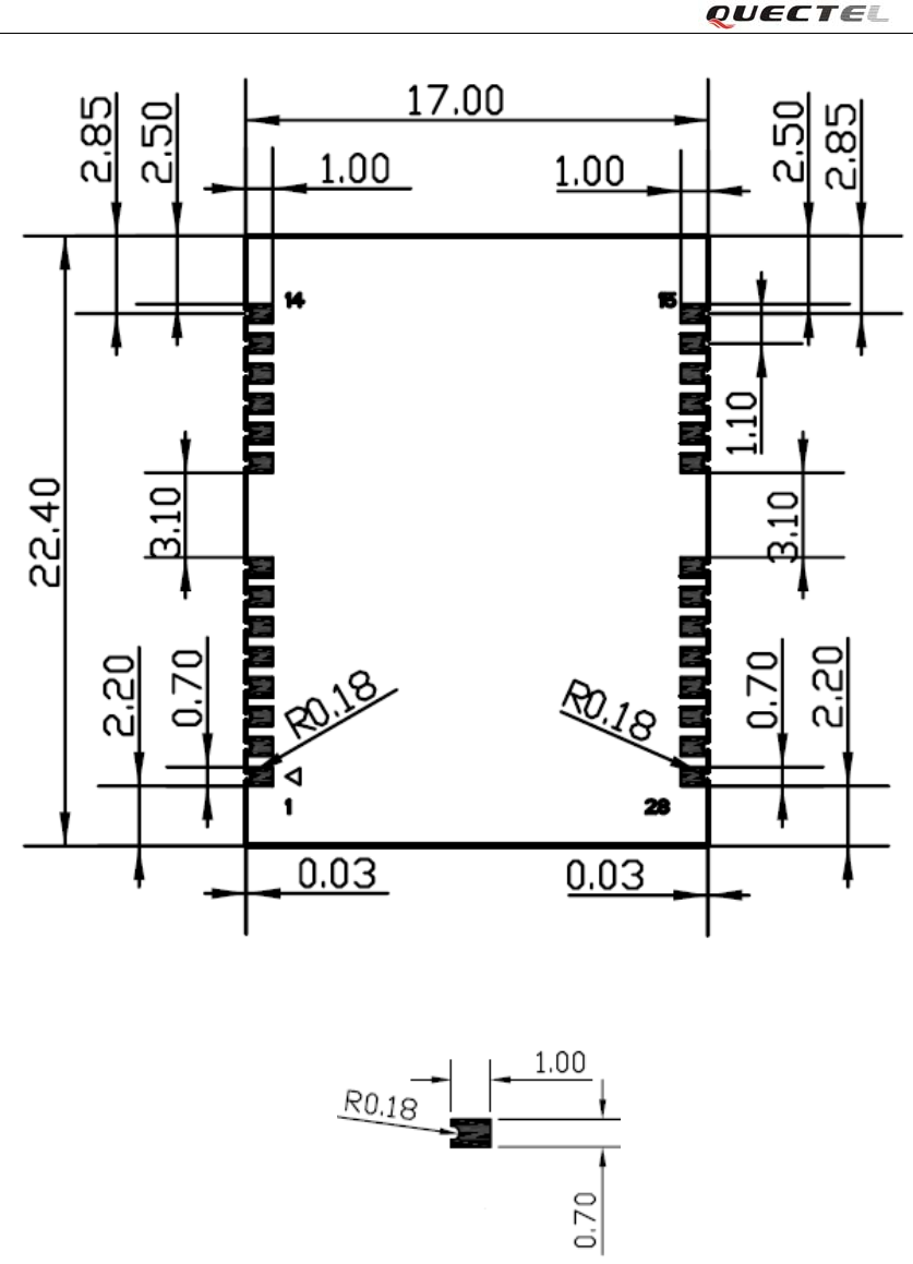
L10 Bottom dimensions(Unit:mm)
PAD Bottom dimensions(Unit: mm)
L10_User_Guide_V1.00 - 11 -
3. GPS Protocol
Please see the document of L10_GPS_Protocol.
4. Compliance with FCC Regulations
FCC Section 15.21 Information to the user
Changes or modifications not expressly approved by the party responsible for compliance could
void the user's authority to operate the equipment.
Section 15.19 Labelling requirements
This device complies with Part 15 of the FCC Rules.
Operation is subject to the following two conditions:
(1) this device may not cause harmful interference, and
(2) this device must accept any interference received, including interference that may cause
undesired operation.
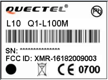
When the L10 is integrated into a final product, the FCC ID label must be visible through a window
on the final device or it must be visible when an access panel,door or cover is easily removed. If not,
a second label must be placed on the outside of the final device that contains the following text:
“Contains FCC ID:XMR-16182009003 ” L10 FCC label is shown as:
Section 15.105 (b)
Note: This equipment has been tested and found to comply with the limits for a Class B digital
device, pursuant to part 15 of the FCC Rules. These limits are designed to provide reasonable
protection against harmful interference in a residential installation. This equipment generates, uses
and can radiate radio frequency energy and, if not installed and used in accordance with the
instructions, may cause harmful interference to radio communications. However, there is no
guarantee that interference will not occur in a particular installation.
If this equipment does cause harmful interference to radio or television reception, which can be
determined by turning the equipment off and on, the user is encouraged to try to correct the
interference by one or more of the following measures:
--Reorient or relocate the receiving antenna.
--Increase the separation between the equipment and receiver.
--Connect the equipment into an outlet on a circuit different from that to which the receiver is
connected.
--Consult the dealer or an experienced radio/TV technician for help.