Quectel Wireless Solutions 16182009004 GPS TRACKER User Manual
Quectel Wireless Solutions Company Limited GPS TRACKER Users Manual
UserManual.wiki
>
Quectel Wireless Solutions
>
16182009004 User Manual
Users Manual
Navigation menu
Upload a User Manual
Namespaces
Wiki Guide
HTML
PDF
Info
Views
User Manual
Discussion / Help
Navigation
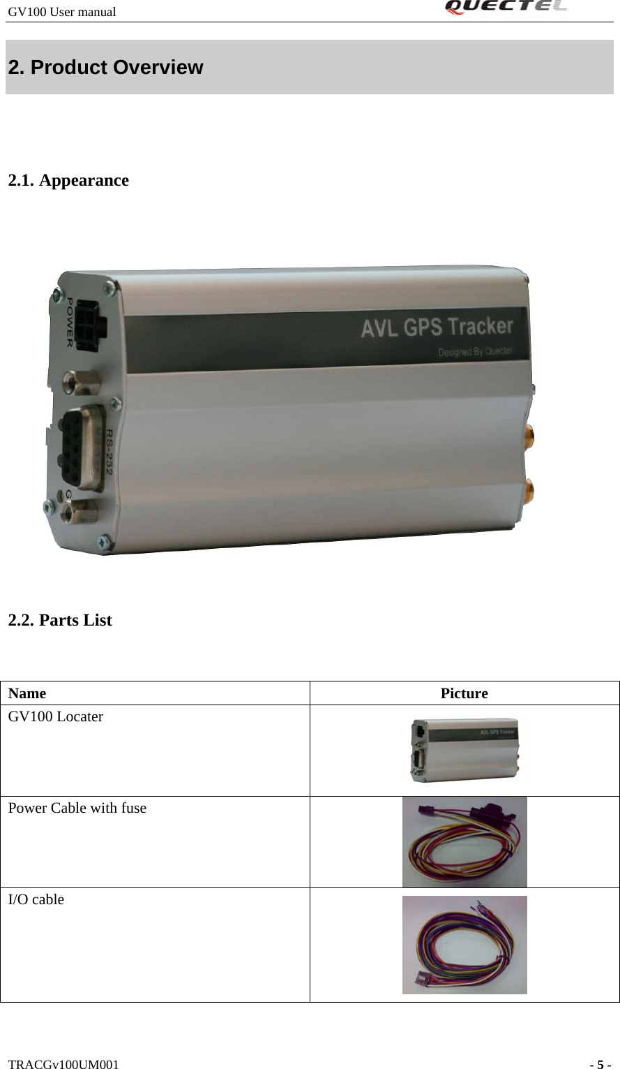
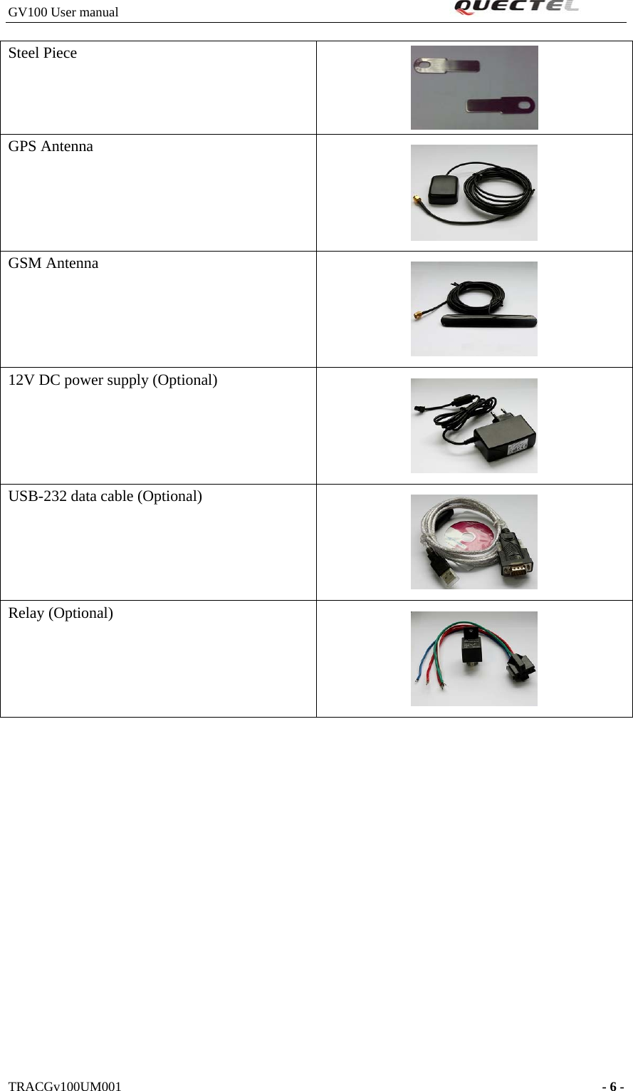
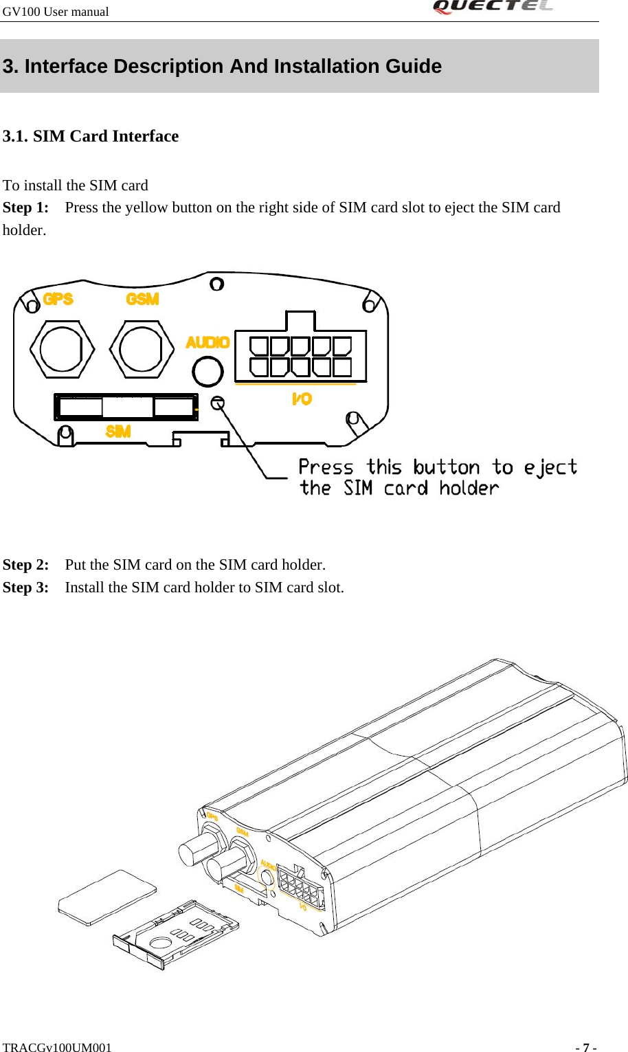
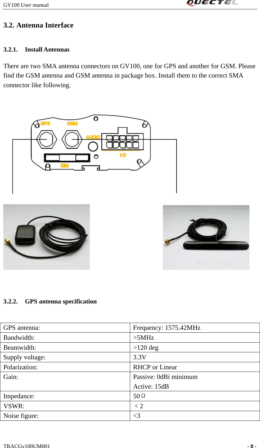
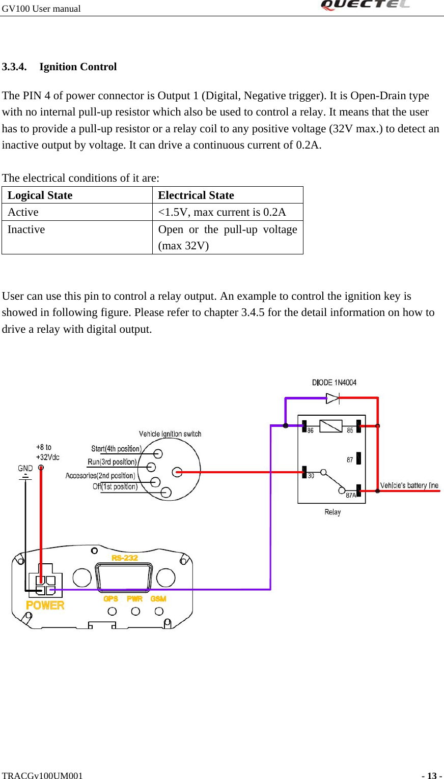
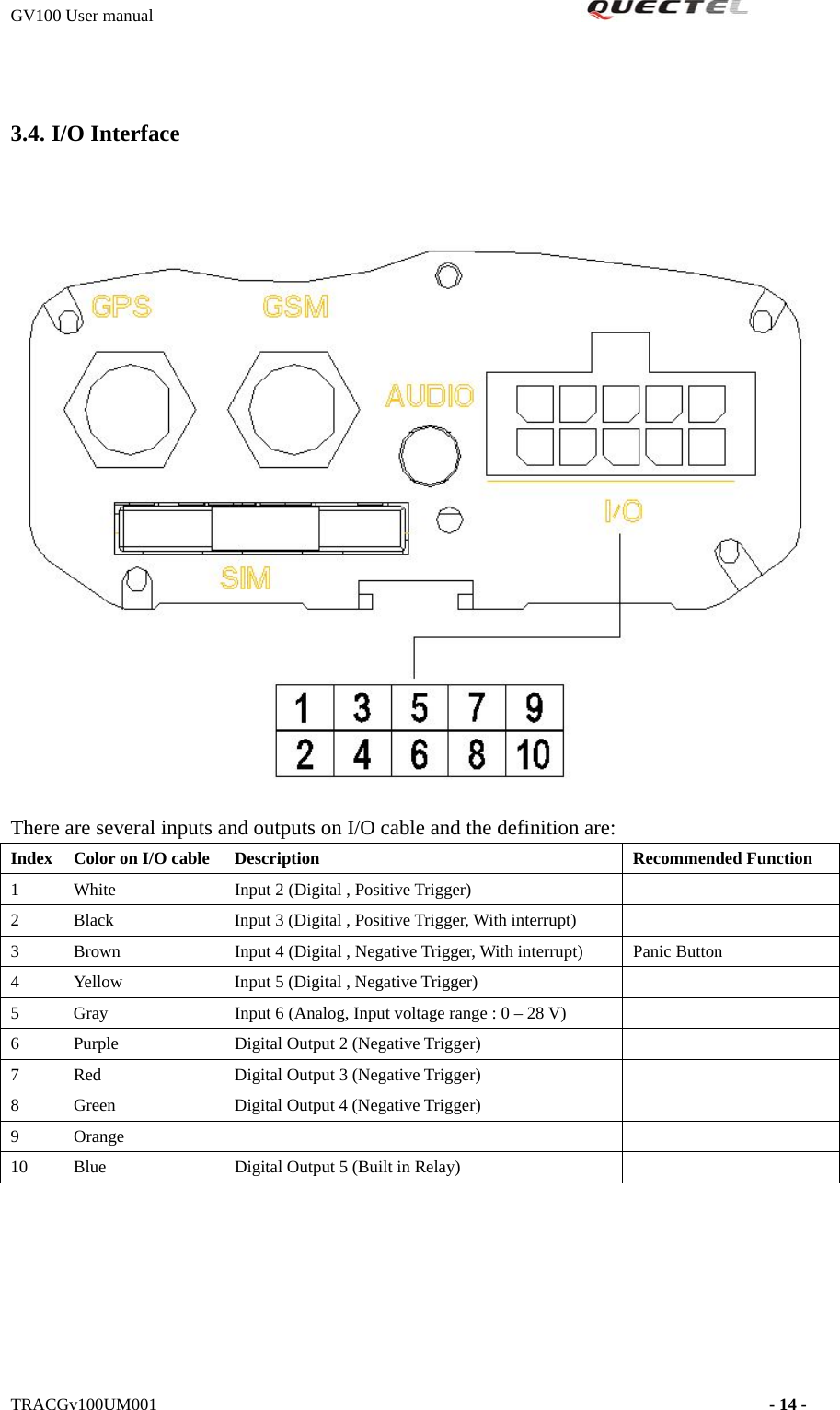
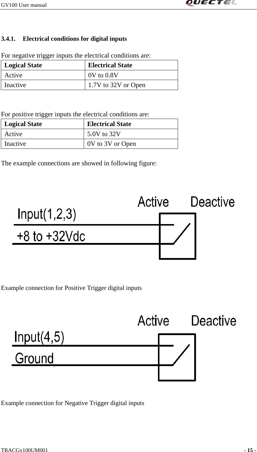
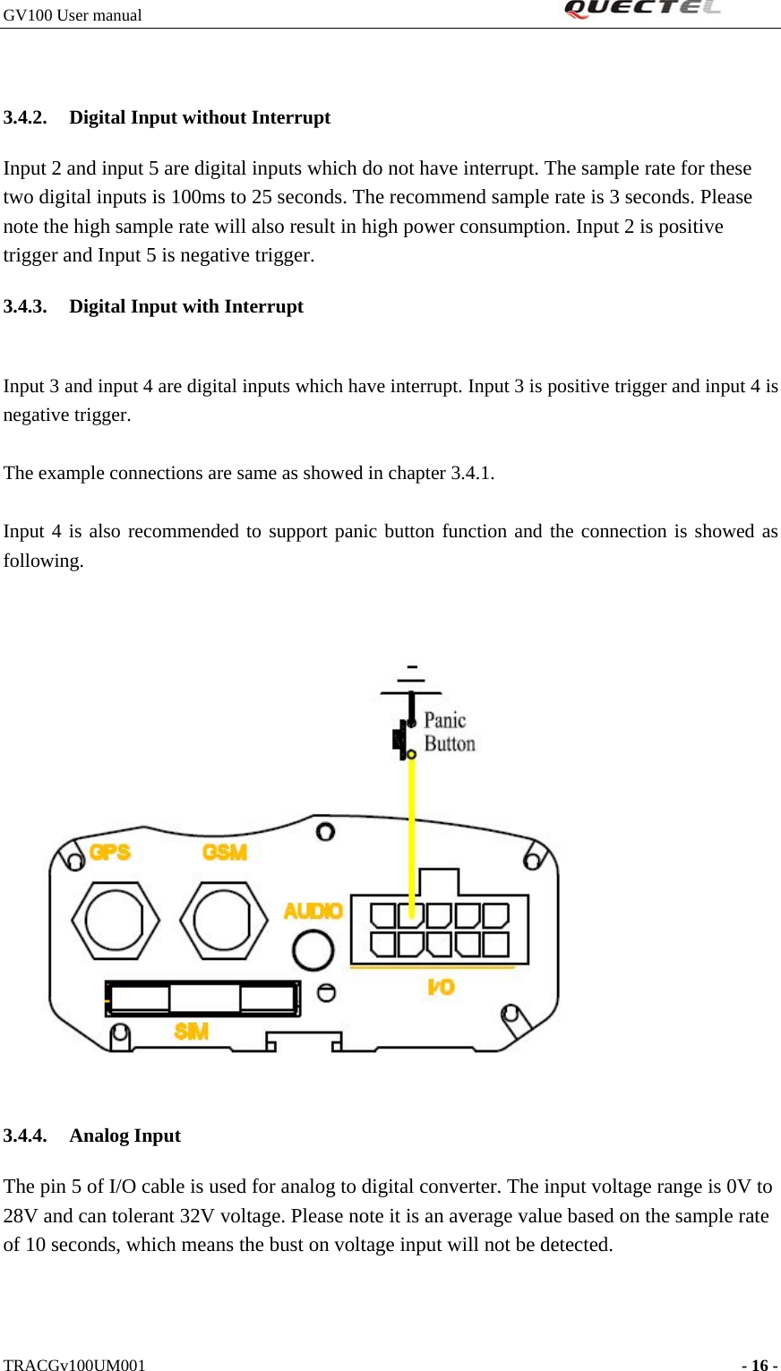
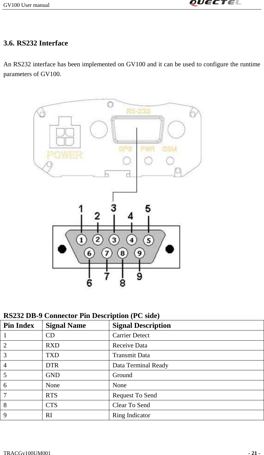
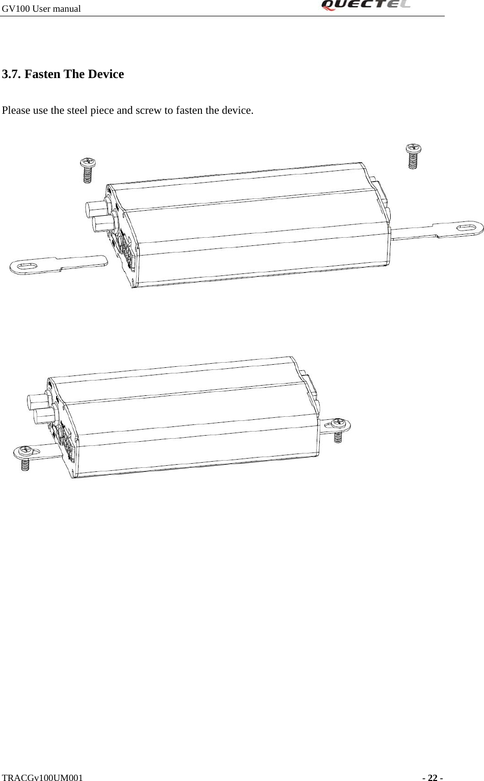
![GV100 User manual 1. Introduction The GV100 is a powerful GPS Locator designed for vehicle tracking or asserts tracking. With superior receiving sensitivity, fast TTFF (Time to First Fix) and Quad-Band GSM frequencies 850/900/1800/1900, its location can be monitored in real time or periodically tracked by a backend server or other specified terminals. The GV100 has multiple input/output interfaces which can be used for monitoring or controlling external devices. Based on the integrated @Track protocol, the GV100 can communicate with a backend server through the GPRS/GSM network to transfer reports of Emergency, Geo-fence boundary crossings, Lower Battery or scheduled GPS position along with many other useful functions. Users can also use GV100 to monitor the status of a vehicle and control the vehicle with its onboard relay output. System Integrators can easily setup their tracking systems based on the full-featured @Track protocol. 1.1. Reference SN Document name Remark [1] GV100 @Track Air Interface Protocol v1 00.PDF The air protocol interface between GV100 and backend server. [2] 1.2. Terms and abbreviations Abbreviation Description TRACGv100UM001 - 4 -](https://usermanual.wiki/Quectel-Wireless-Solutions/16182009004/User-Guide-1216974-Page-5.png)