Quest Payment Systems 1601 UT430 Unattended Payment Terminal User Manual 152 0004 14 UT430 Installation Guide
Quest Payment Systems Pty Ltd UT430 Unattended Payment Terminal 152 0004 14 UT430 Installation Guide
User Manuel
Unattended Payment Terminal
Installation & User Guide
152-0004-14
Copyright
This document contains proprietary information that is protected by copyright. All rights are
reserved. No part of this document may be disclosed to third parties, photocopied, reproduced, or
translated into another language without the prior written permission of Quest Payment Systems.
This document is subject to change without notice.
Contents
Introduction........................................................................................................................ 1
Product Overview ............................................................................................................... 2
Machine Requirements ...................................................................................................... 3
Installation into a Machine ................................................................................................ 7
Power Requirements & Communications ........................................................................ 10
Communications Setup .................................................................................................... 11
Connecting a Printer (optional) ........................................................................................ 16
3G Enabling ...................................................................................................................... 16
3G Enabling (optional) ...................................................................................................... 17
Contactless - SAM Card Installation (optional) ................................................................ 21
Commissioning UT430 ...................................................................................................... 22
General Operation ............................................................................................................ 23
Software Controls ............................................................................................................. 23
General Cleaning .............................................................................................................. 25
Stolen Devices .................................................................................................................. 26
FCC Statement .................................................................................................................. 29
IC Statement ..................................................................................................................... 29
Warranty .......................................................................................................................... 30
Appendices ....................................................................................................................... 32

152-0004-14 UT430 Installation Guide Page 1
11
1
Introduction
Please read and understand these guidelines to ensure correct installation and successful
commissioning of your UT430 Payment Terminal.
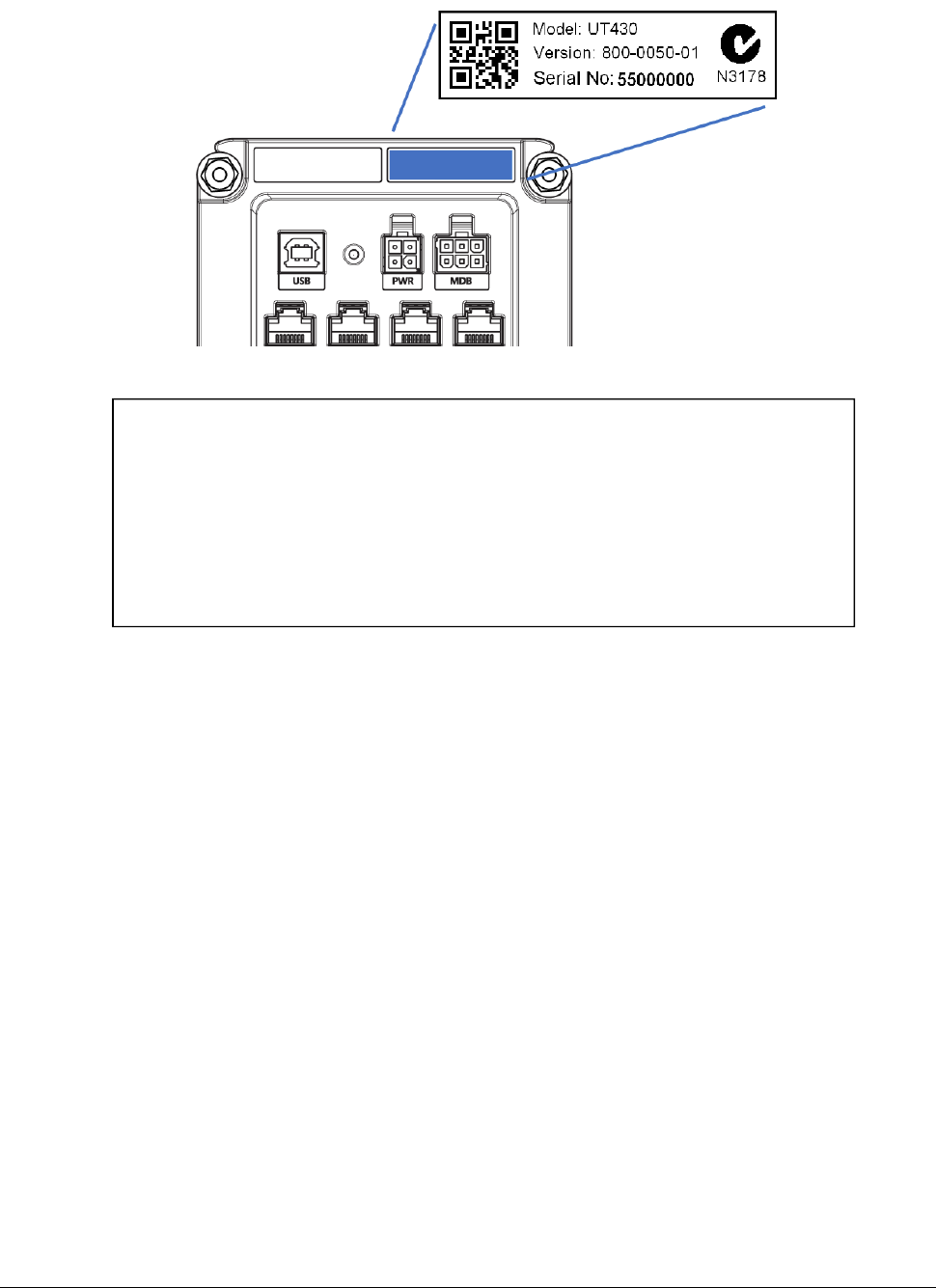
Note: The communication and power ports available on your UT430 will depend on the
configuration chosen at the time of purchase. This guide illustrates a UT430 with all possible ports
included.
Parts Checklist
Please check that your 'UT430 Standard Kit’ contains the following items:
Optional Accessories
(available for purchase. Contact Quest on +61 3 8807 4400)
UT430 Payment Terminal
2m Straight Cable (QT720 DB9F to 10P10C)
12V, 1.2A Plug pack
Fastener Kit (2x M4 Nylok Nuts, 2x M4-25L Thumbscrews, 4x Plain Washers)
1. USB cable (To connect UT430 to the Machine controller)
2. Ethernet Communications module (Ethernet cable required, not supplied).
3. 3G Communications module
152-0004-14 UT430 Installation Guide Page 2
22
2
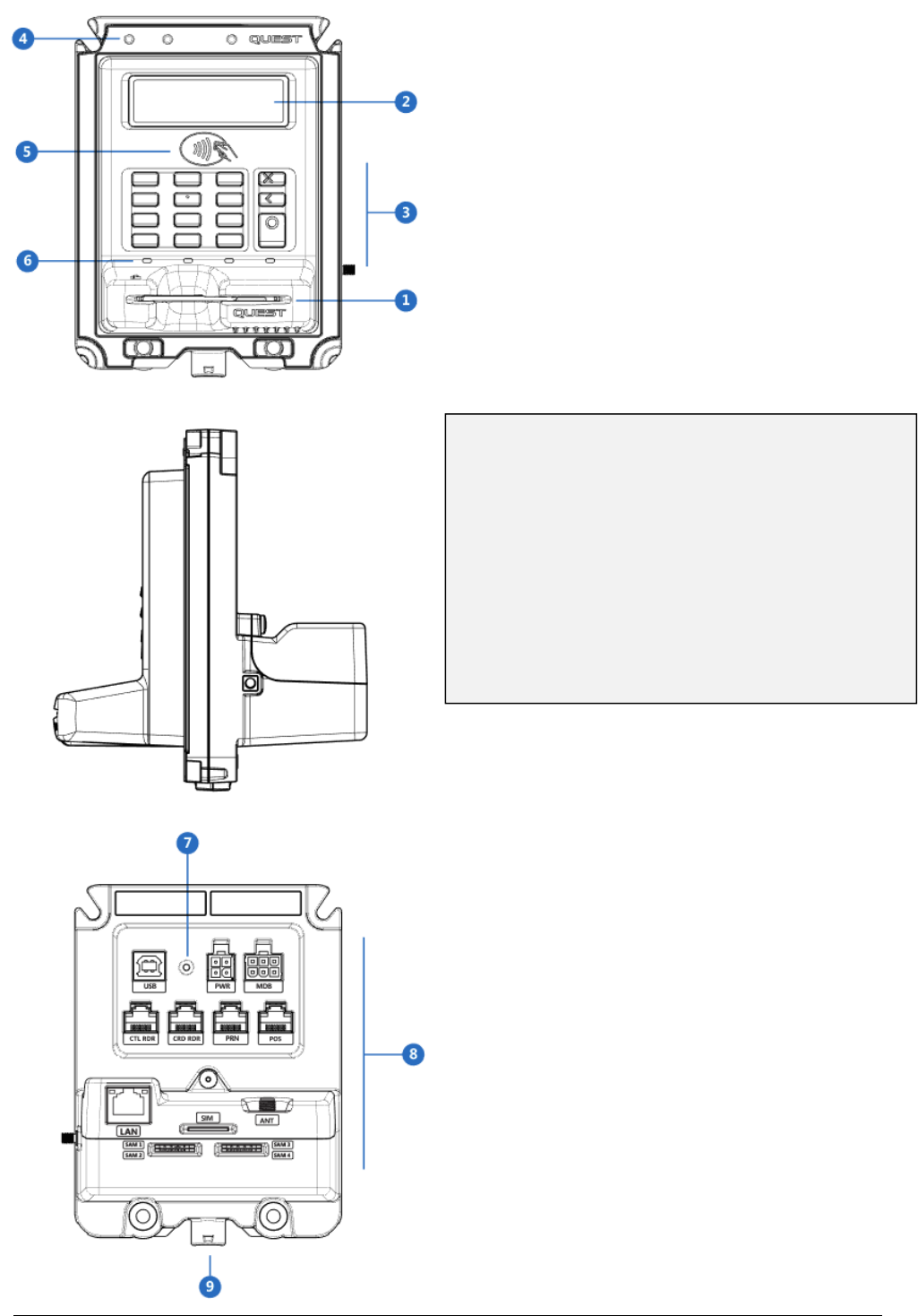
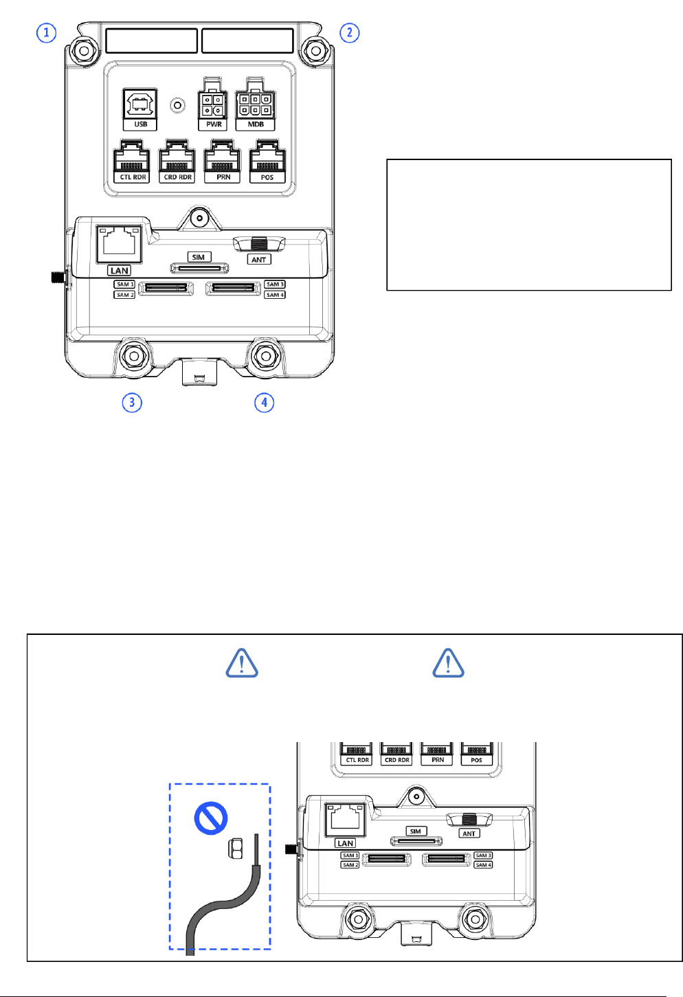
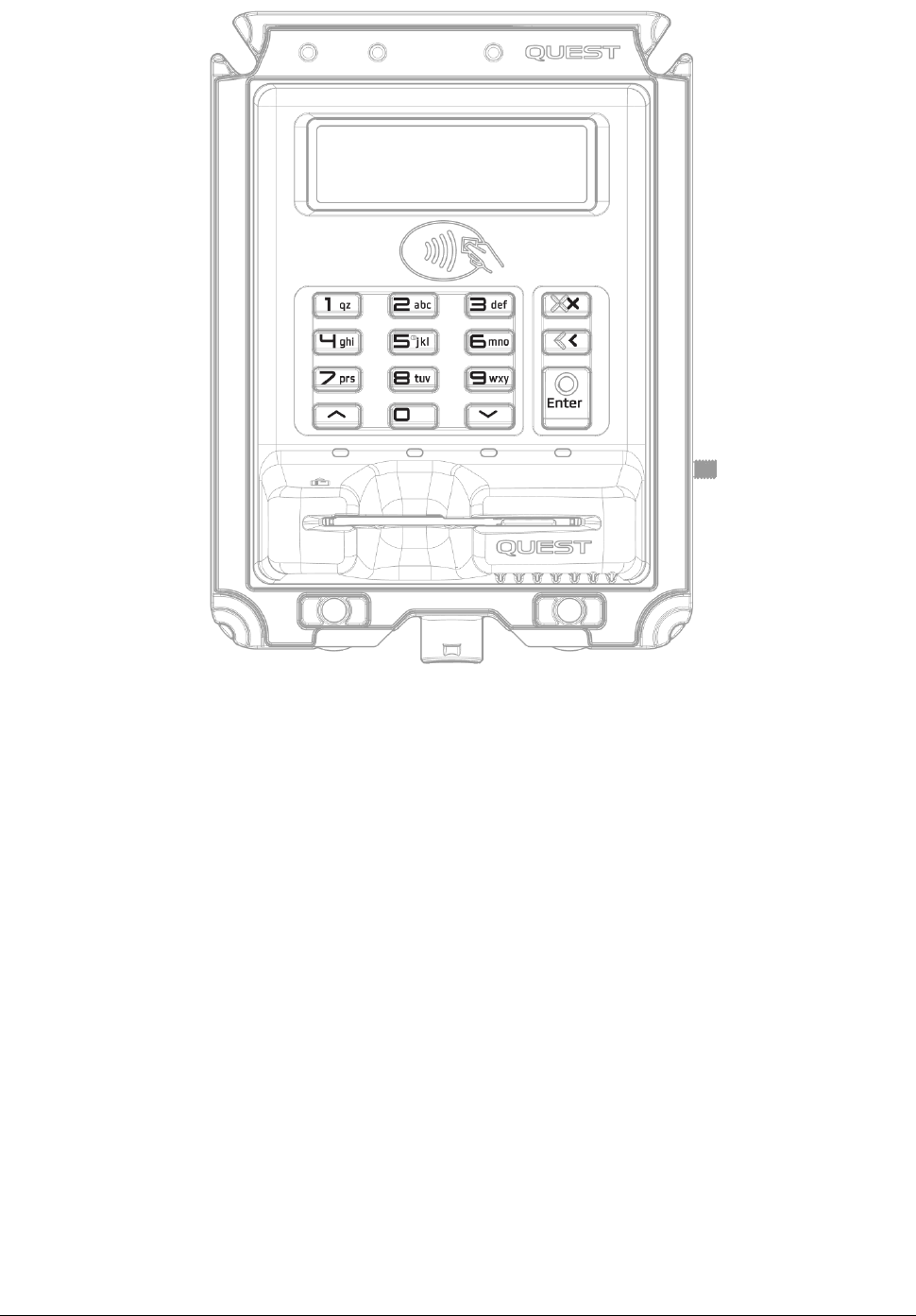
Product Overview
1. Contact Card Reader
2. Display
3. PIN Entry keypad
4. Removal detection switches
5. Tap Zone - Contactless cards
6. Contactless transaction status indicators
7. Power indicator
8. Backplane connections
9. Drain tube attachment
152-0004-14 UT430 Installation Guide Page 3
33
3
Machine Requirements
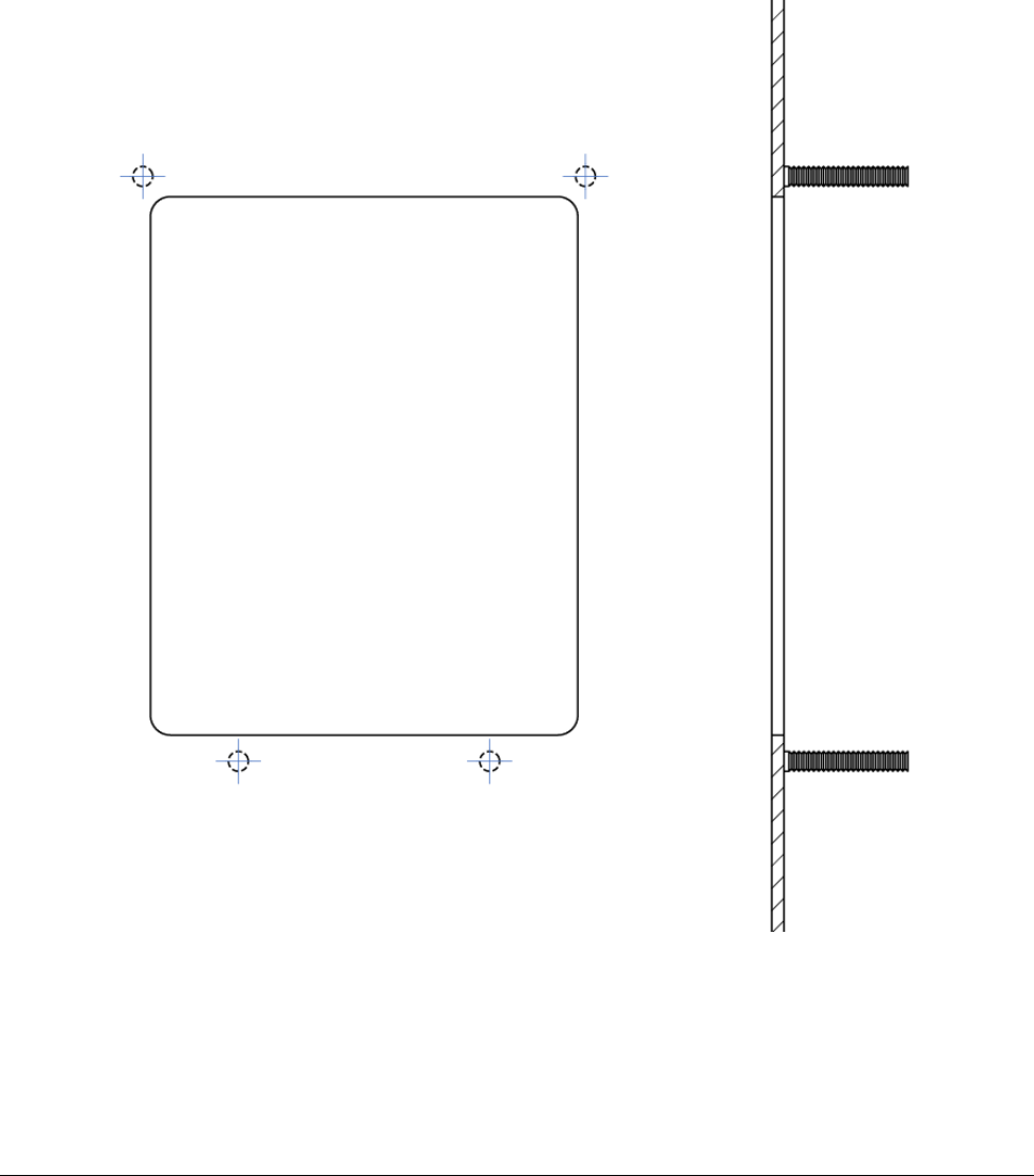
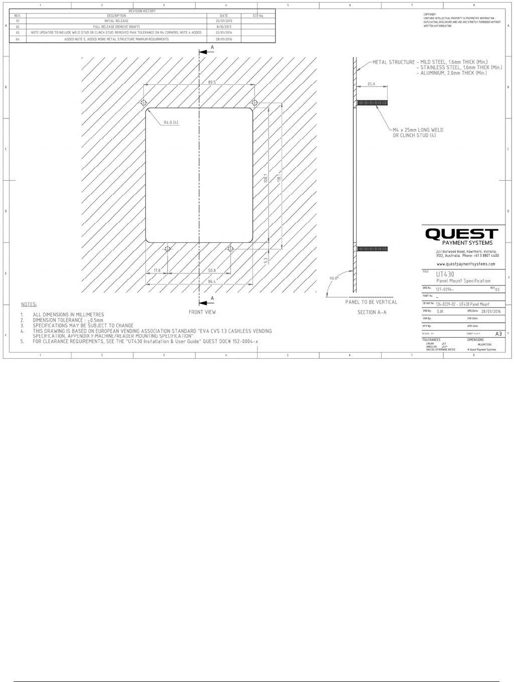
PANEL MOUNTING
UT430 has been designed to fit the recommended hole size as prescribed by the European
Vending Association, document: CASHLESS VENDING SPECIFICATION EVA CVS 1.3
1. Cut-out Size: 86.4 x 108.7, 4mm Max Corner Radius (3mm minimum)
2. Mounting Substrate: Minimum - 1.6mm Mild /Stainless steel, 2.0mm Aluminium
3. Hardware required on Panel: M4 x 25mm Studs (Clinch or Weld)
4. Fasteners required: See Fastener Kit (provided)
5. Tools required: 7mm (M4) Socket
PANEL CUTOUT- See Appendix A for a complete detailed drawing
152-0004-14 UT430 Installation Guide Page 4
44
4
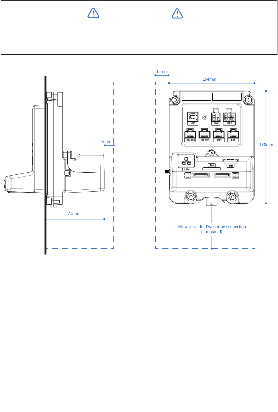
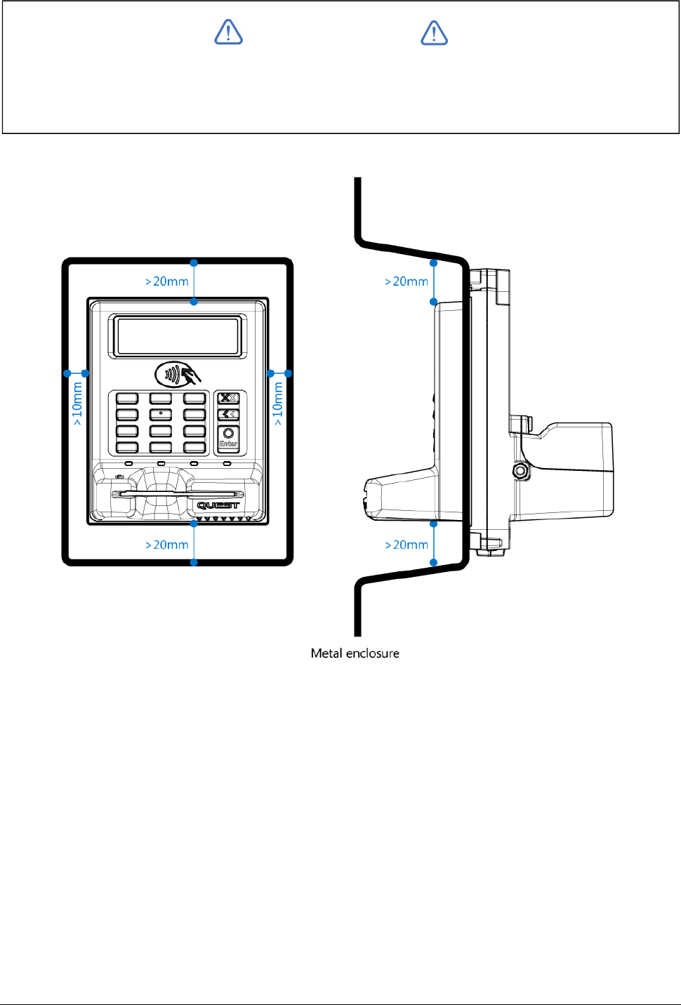
INTERNAL CLEARANCE SPACE REQUIRED
Please observe the space requirements inside the machine.
IMPORTANT
Note: If UT430 is connected via Ethernet, a clearance greater than 20mm may be required
behind UT430 (dependant on cable style)
152-0004-14 UT430 Installation Guide Page 5
55
5
EXTERNAL CLEARANCE SPACE REQUIRED
Please observe the space requirements outside the machine.
IMPORTANT
Note: Ensure the sides of the metal enclosure near the protruding portion of the UT430 are kept
the minimum distances away as shown below. This will ensure reliable operation of the
Contactless reader.

152-0004-14 UT430 Installation Guide Page 6
66
6
MECHANICAL SECURITY
If UT430 is mounted on a hinged door or fascia panel, ensure the door or panel cannot be
removed during normal operation. This aspect is important to maintaining your PCI compliance.
RECOMMENDATIONS FOR PIN ENTRY PRIVACY
1. It is imperative that UT430 is installed in the machine in such a manner that prevents visual
observation of the PIN entry process. To achieve this, ensure that:
2. Display instructions for the card holder to shield the PIN entry with his/her body.
3. If security cameras are to be used on site, they must be installed in such a manner that it is
not possible to view or record the PIN entry process.
152-0004-14 UT430 Installation Guide Page 7
77
7
Installation into a Machine
TOOLS REQUIRED
1. 7mm (M4) Socket
ASSEMBLY TO MACHINE
1. Ensure machine has been designed in accordance with the recommended cut out and
mounting studs prior to beginning installation (see Appendix A)
2. From inside the machine, place UT430 through the cut out and over the internal mounting
studs. (UT430 is designed to protrude through the hole in the machine)
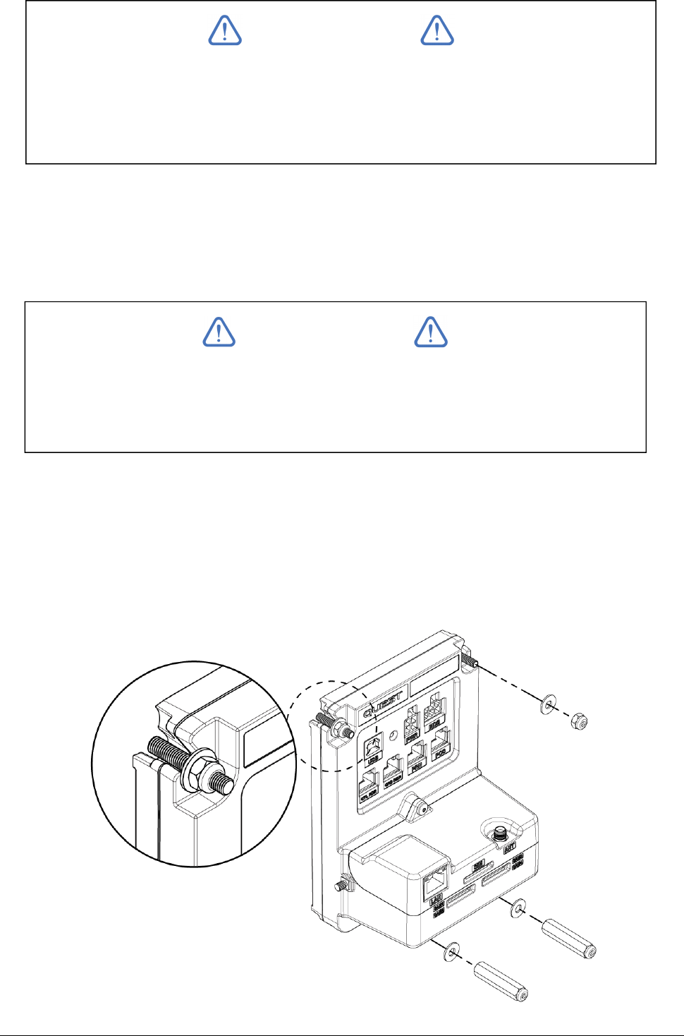
3. Starting with the top 2 studs, fit the provided plain washer and M4 Nylok nuts onto the
studs. Ensure Nylok nuts are firmly tightened with #7 Socket Tool.
IMPORTANT
As a requirement of PCI v3.x, UT430 includes a 'Removal Detection' feature which is
comprised of physical sensors which detect if UT430 has been properly installed or
removed. Only correct installation will allow transactions to occur.
IMPORTANT
IMPORTANT: Ensure UT430 is fitted with the Black Silicone Gasket on the internal
flange. This component is critical to successfully installing the device.
152-0004-14 UT430 Installation Guide Page 8
88
8
4. Fit plain washers on both bottom studs and fit the M4 Thumbscrews - finger tight only.
5. Check operation of Card slot by inserting a card, if the card does not slide freely, loosen the
thumbscrews until the card slot is free running.
6. Ensure there is no rattle and no visible gap between the flange of UT430 and the machine
mounting surface.
7.
Mechanical installation of UT430 to the machine is now complete. Visually inspect the
outside of the Machine and UT430. Also check that the machine can be closed and no
interference exists between UT430 and other internal components / mechanisms.
IMPORTANT
Do not connect to the UT430 earth point. The earth point is not to be used.
FASTENER LOCATIONS
1.
Plain Washer + M4 Nylok Nut
2.
Plain Washer + M4 Nylok Nut
3.
Plain Washer + M4 Thumbscrew
4.
Plain Washer + M4 Thumbscrew
152-0004-14 UT430 Installation Guide Page 9
99
9
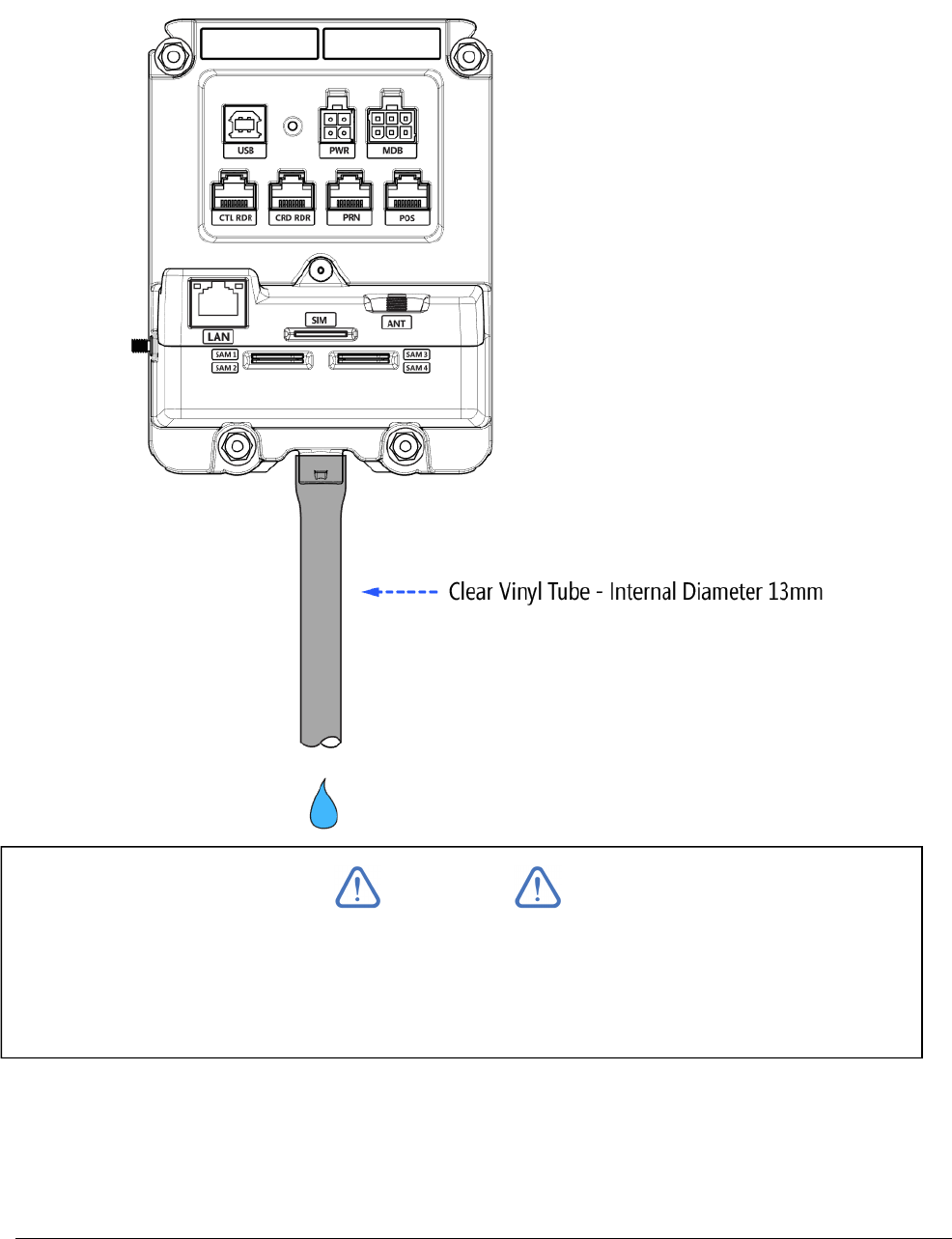
DRAIN TUBE
If UT430 is situated where moisture could enter the card slot, a Vinyl drain tube should be fitted to
direct water safely out of the machine. The tube can be pushed onto the barb fitting on UT430.
The other end of the tube must exit the machine in a safe manner. Length and exit location of
tube to be determined by machine manufacturer.
Hazard: Do not drain water near any electrical devices / connections
NOTE
Vinyl Drain tube is not supplied as standard by Quest.
Periodically check the tube for build-up and blockages. A blockage could prevent
moisture draining out of the UT430 card slot.
152-0004-14 UT430 Installation Guide Page 10
1010
10
Power Requirements & Communications
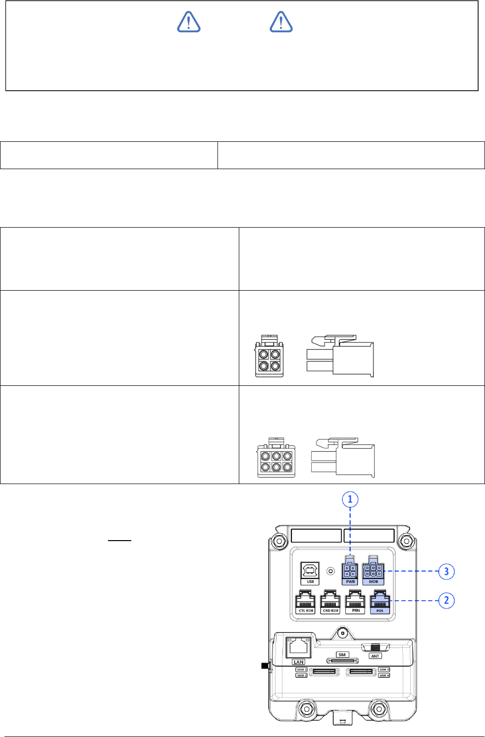
POWER REQUIREMENTS
Input Voltage Range 5V-34V DC, 14.4W max
Power can be supplied to UT430 in 3 different ways dependant on your implementation. Choose
one method below:
1. POS Port (using the Quest Serial
Connection Kit with 12V adaptor – supplied
as standard)
RJ 8P8C
2. PWR Port
Mini Universal Mate-N-Lok (TE Connectivity)
- 4 POS Plug Housing (Mfr Part No. 172167-1)
3. MDB Port
MiniFit Jr Plug Housing, Dual Row (Molex)
- 6 POS Plug Housing (Part No.39-01-2060)
Note: When UT430 is connected to a
Machine controller and power is supplied, a
green LED will illuminate on the back of
UT430 (next to PWR connector).
NOTE
The UT430 must be supplied by a Limited Power Source (LPS) or a Class 2 power
supply in accordance with the U.S. National Electrical Code.
152-0004-14 UT430 Installation Guide Page 11
1111
11
Communications Setup
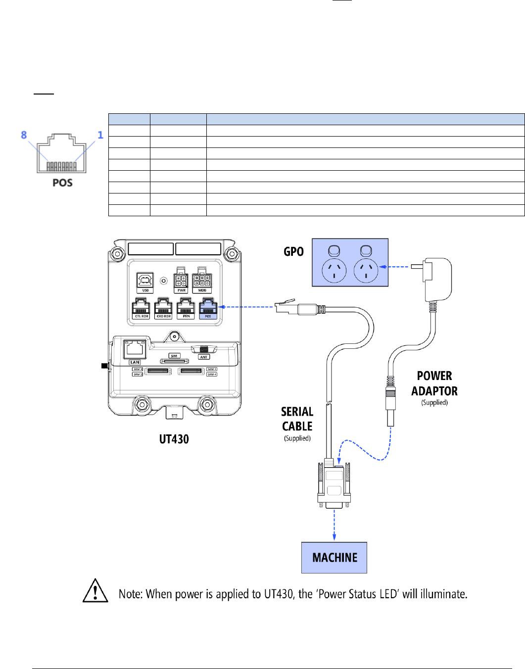
1. SERIAL CONNECTION
Connect UT430 following the instructions on the diagram below:
the Modular plug to the UT430 modular socket labelled POS
the DB9 POS plug to the Machine controller
the 12V Power Adaptor to a 240V Power outlet (GPO)
POS port pinout on UT430
Pin Signal Description
1 NC Not Connected
2 POS-TX POS Transmit (Output)
3 POS-RX POS Receive (Input)
4 POS-VS POS 12V Supply Voltage ** Required, if powering via serial port on machine**
5 GND Ground
6 POS-RTS POS Request to Send (Output) **Optional**
7 POS-CTS POS Clear to Send (Input) **Optional**
8 NC Not Connected
152-0004-14 UT430 Installation Guide Page 12
1212
12
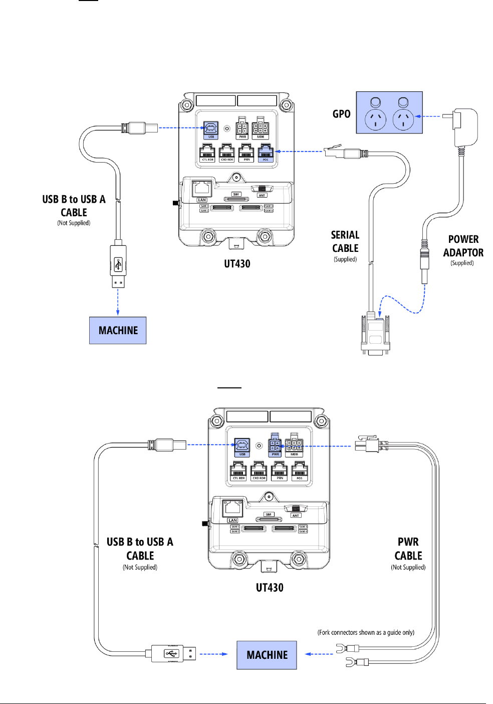
2. USB CONNECTION (OPTIONAL)
UT430 has a full size 'B type' socket. Connect the 'B type' end of your USB cable to the socket
labelled USB. Connect the other end (type A) to the USB port on the machine controller.
The USB port is for communications only. Power must be supplied by either:
1. Using the Quest Power supply
2.
Or, fitting a 12V cable to the PWR port
(See Power requirements section in this document)

152-0004-14 UT430 Installation Guide Page 13
1313
13
USB port pinout on UT430
Pin Signal Description
1 VCC +5V
2 D- Data -
3 D+ Data +
4 GND Ground
152-0004-14 UT430 Installation Guide Page 14
1414
14
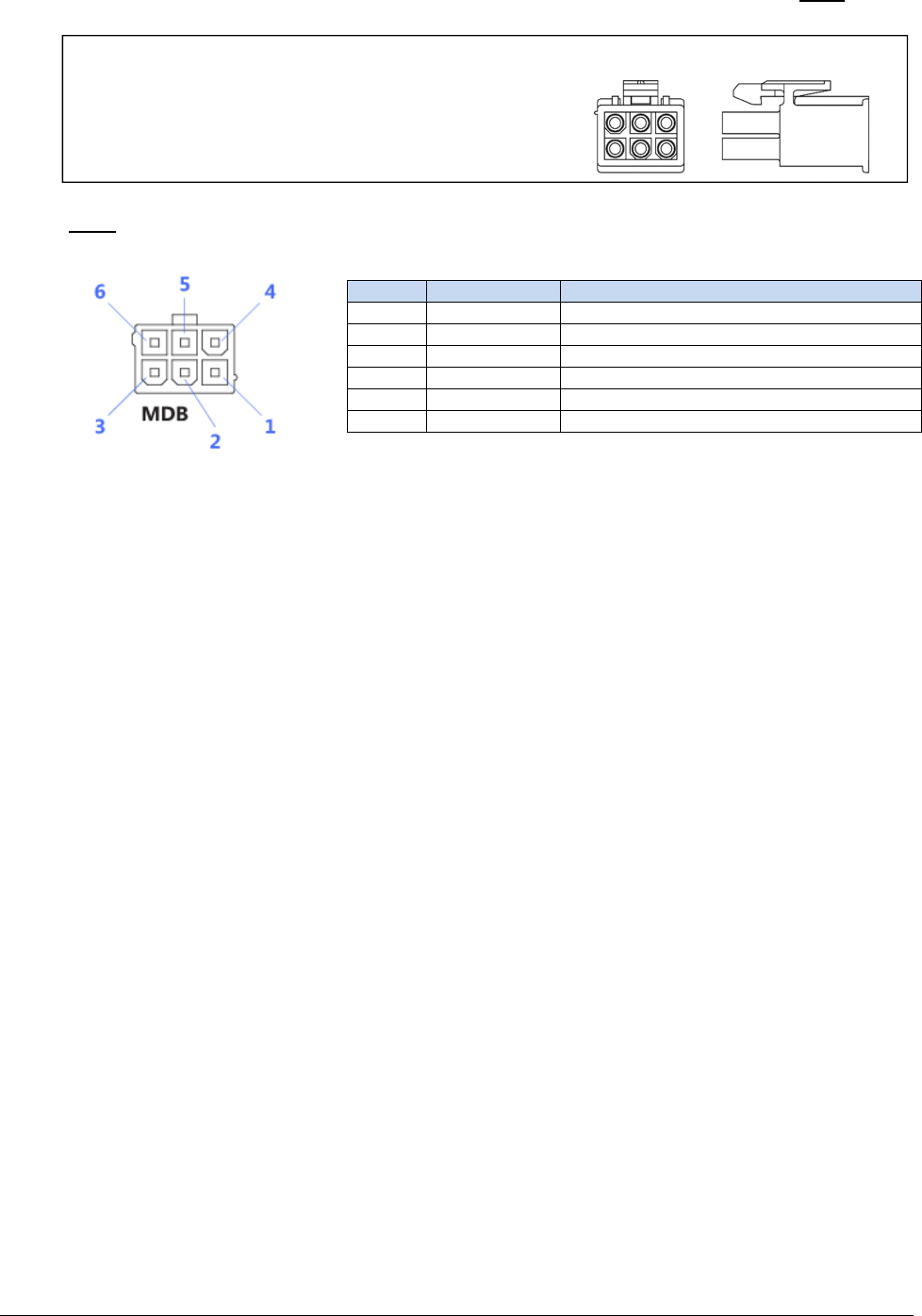
3. MDB (MULTI DROP BUS) CONNECTION (OPTIONAL)
Connect UT430 by fitting:
the MDB cable from the machine controller to the 6 pin socket labelled MDB
MDB port pinout on UT430
Pin Signal Description
1 MDB-VS MDB Supply Voltage
2 GND Ground
3 WAKEUP MDB Bidirectional Wakeup
4 MDB-TX MDB Transmit (Output)
5 MDB-RX MDB Receive (Input)
6 MDB-GND MDB Isolated Ground (for MDB-TX and -RX)
MiniFit Jr Plug Housing, Dual Row (Molex)
- 6 POS Plug Housing (Part No.39-01-2060)
152-0004-14 UT430 Installation Guide Page 15
1515
15
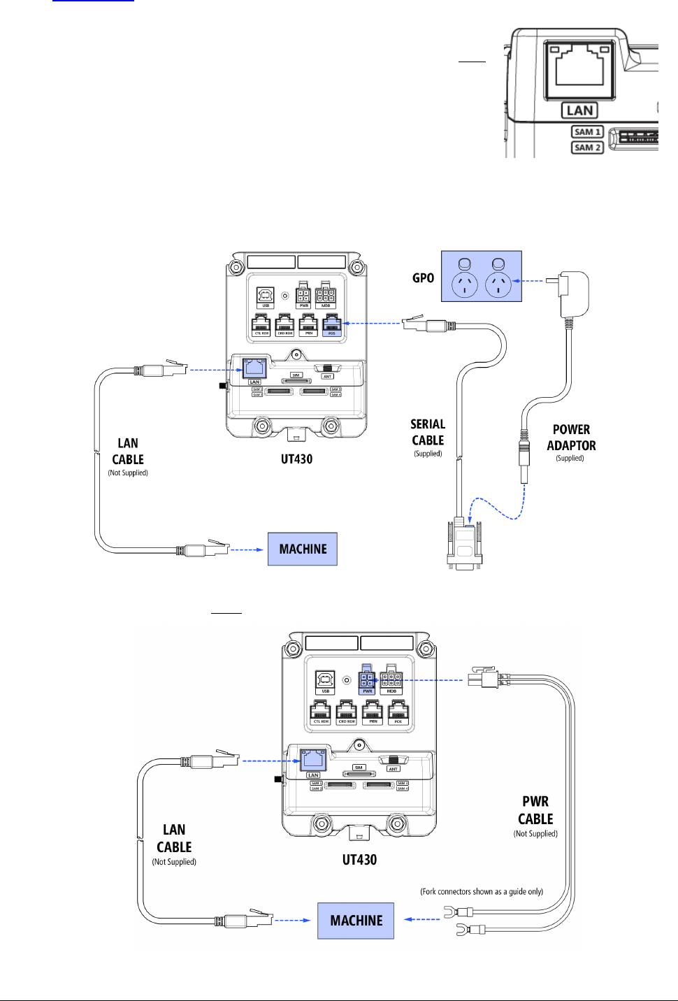
4. ETHERNET CONNECTION (OPTIONAL)
UT430 has a modular 8P8C connector (commonly referred to as RJ45) that follows the
TIA/EIA-568 wiring standard. If an optional Ethernet Communication module has been
fitted to UT430:
Connect your LAN Cable to the UT430 socket labelled LAN
The Ethernet port is for communications only. Power must be supplied by either:
1. Using the Quest Power supply
2. Or, fitting a 12V cable to the PWR port (See Power requirements section in this document)
152-0004-14 UT430 Installation Guide Page 16
1616
16
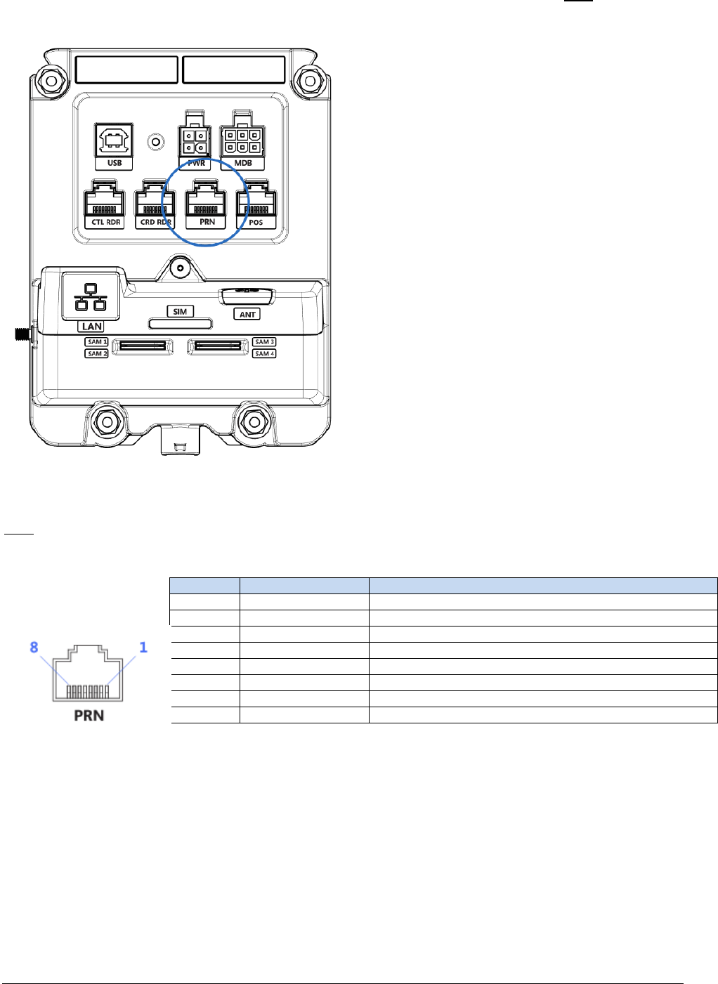
Connecting a Printer (optional)
UT430 allows connection of one Slave RS-232 Serial Receipt printer.
Connect the Modular plug from the printer to the socket on UT430 labelled PRN
PRN port pinout on UT430
3G Enabling
Pin Signal Description
1 NC Not Connected
2 PRN-TX External Printer Transmit (Output)
3 PRN-RX External Printer Receive (Input)
4 NC Not Connected
5 GND Ground
6 PRN-RTS External Printer Request to Send (Output)
7 PRN-CTS External Printer Clear to Send (Input)
8 NC Not Connected
152-0004-14 UT430 Installation Guide Page 17
1717
17
3G Enabling (optional)
UT430 is designed to accept a 3G Communications module (only available from Quest). The
standard configuration of UT430 does not include this 3G module unless arranged prior. However,
the module can be fitted in the field by a qualified technician (contact Quest to obtain detailed
instructions).
To enable 3G communication on the UT430 you will need the following:
1. 3G Communications module from Quest, installed into the UT430
2. 1/4" SMA Coaxial External Antenna
3. Cellular SIM card (Size: Mini SIM, 25mm L x 15mm W)
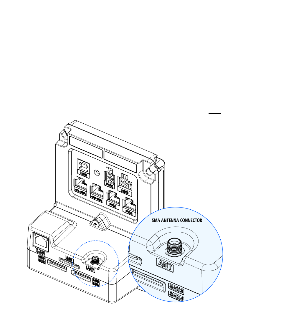
ANTENNA REQUIREMENTS
When choosing a broadband antenna, ensure the connector on the cable is:
• Standard Male SMA
• Screw-on coupling, 1/4″- 36 threads (internally threaded)
• Male Pin (Standard polarity)
INSTALLATION
1. Ensure UT430 is off (no power connected)
2. Locate the SMA connector on the back of the UT430 (labelled ANT)

152-0004-14 UT430 Installation Guide Page 18
1818
18
152-0004-14 UT430 Installation Guide Page 19
1919
19
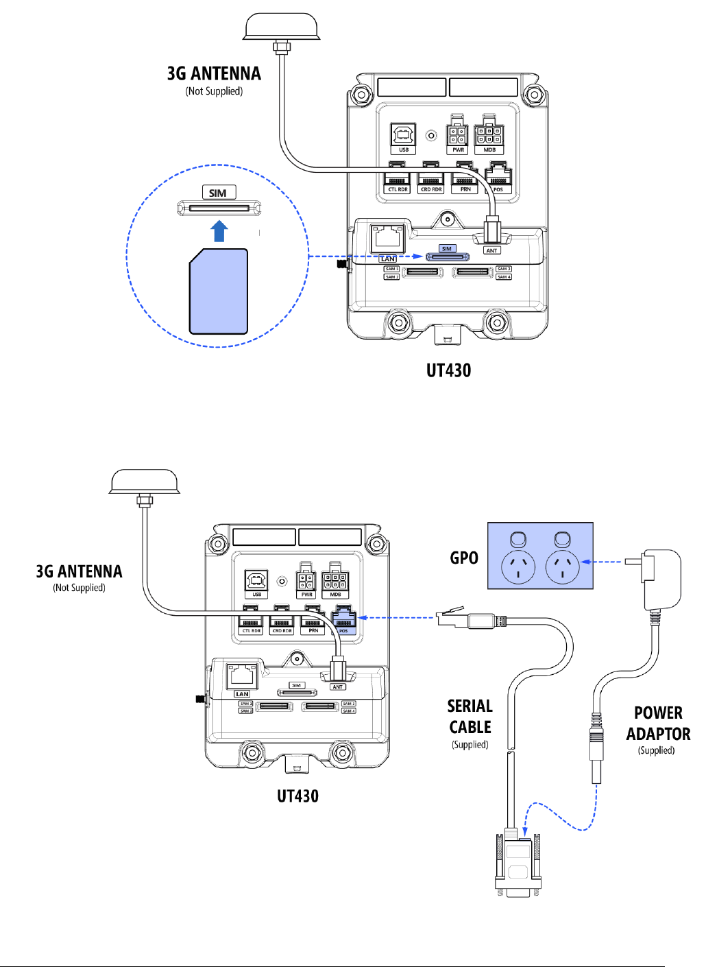
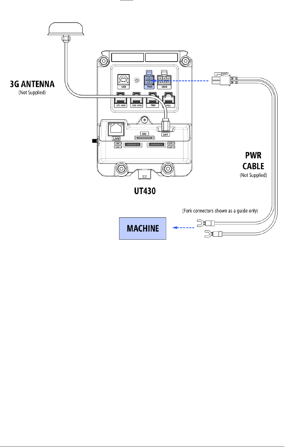
3. Connect your external antenna (do not over tighten). Note: If fitted, remove the protective
cap from the SMA on UT430 and screw the antenna cable onto the SMA
4. Orientate your SIM Card as shown below and push it into the slot marked SIM until you feel
a click, now release your finger
5. Connect power. Power must be supplied by either:
a. Using the Quest Power supply
152-0004-14 UT430 Installation Guide Page 20
2020
20
b. Or, fitting a 12V cable to the PWR port (See Power requirements section in this document)
TO REMOVE THE SIM CARD
1. To remove the SIM card, push to eject it, then simply pull the card out.
152-0004-14 UT430 Installation Guide Page 21
2121
21
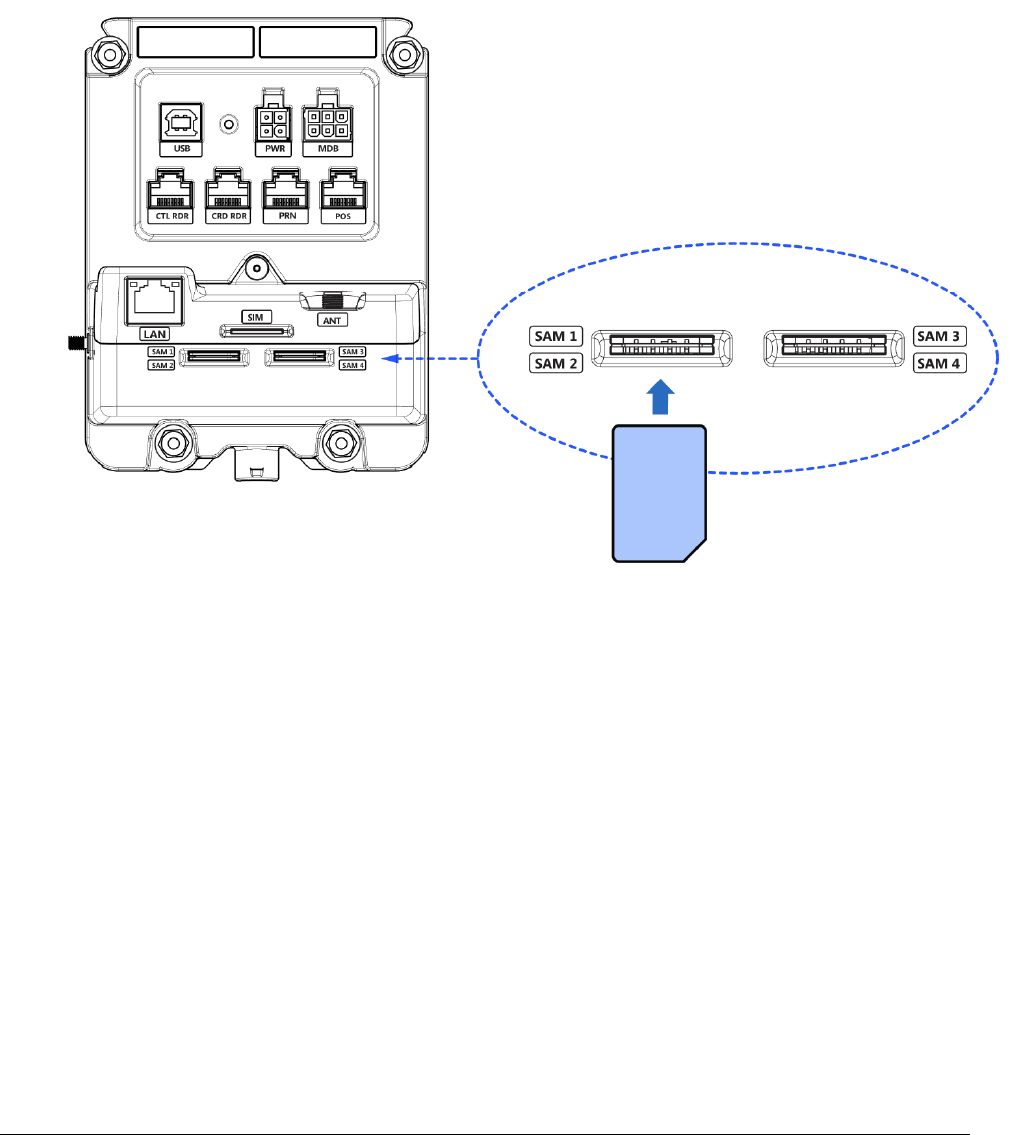
Contactless - SAM Card Installation (optional)
If you require SAM functionality, fit a SAM card as per instructions below.
• Capacity: 4 Slots
• Card Size: Mini SIM (25.00mm Long x 15.00mm Wide)
• Fit the SAM cards in order (ie. If fitting only one SAM, fit it to the slot labelled SAM1)
INSTALLATION
1. Orientate the SAM Card as shown below and push into slot until card stops. (Note: a fully
installed SAM card will protrude 4mm)
REMOVAL
1. To remove a SAM card, use your fingers to pinch the protruding portion of the card and
withdraw it.

152-0004-14 UT430 Installation Guide Page 22
2222
22
Commissioning UT430
Commissioning a UT430 can only take place once the unit is fully installed into the machine as
described earlier in this document.
UT430 is preloaded by Quest with your nominated Bank’s keys, and an agreed Passcode file.
Once the installer completes the first installation of UT430 into the machine and connects power,
the device will be ready for normal operation.
If anyone disassembles the UT430 from the machine after the first installation (even if power
remains connected), the removal detection mechanism on the UT430 will activate, and transaction
processing will be disabled.
To re-enable transaction processing, you will need to contact Quest. The Quest Support desk will
generate a new Unlock / Passcode file which is required to re-commission UT430.
This process forms part of your PCI Compliance.
Quest Support Desk
Support Phone: +61 (3) 8807 4444
Support Email: support@questps.com.au
152-0004-14 UT430 Installation Guide Page 23
2323
23
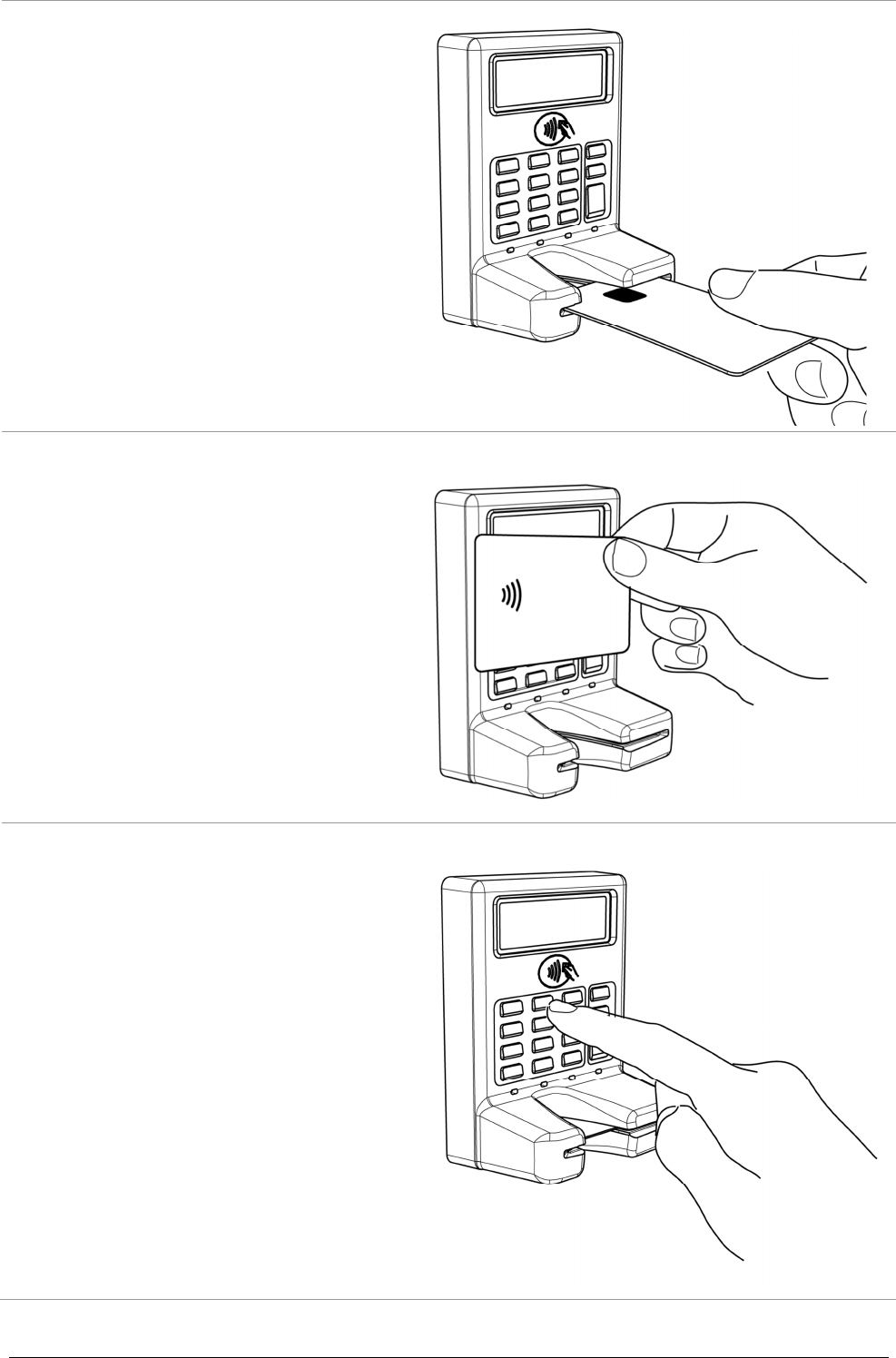
General Operation
When prompted, insert your card with the
magnetic stripe facing down and to the
right (if the card has a Chip, it should face
upwards).
Push the card all the way in until it stops. If
the card has a chip, then leave the card
inserted and follow the prompts.
If the card is Magnetic stripe only, you will
be prompted to remove the card (UT430
will read the magnetic stripe when
withdrawing the card from the device)
When prompted, tap your Contactless
enabled card near the contactless symbol.
The 4 light indicators will illuminate
indicating transaction progress.
If appropriate, you may be prompted to
select an account type.
Press 1 for CHQ
Press 2 for SAV
Press 3 for CR
Software Controls
152-0004-14 UT430 Installation Guide Page 24
2424
24
UT430
The following section outlines commands that can be performed on the UT430 Keypad.
1. To accept a prompt: Press Enter
2. To decline a prompt: Press X (Cancel)
3. To enter menu: Hold X (Cancel) & Press 4
4. To move UP the menu list: Press ^
5. To move DOWN the menu list: Press v
6. To perform a Reboot: Hold X (Cancel) & Press 8

152-0004-14 UT430 Installation Guide Page 25
2525
25
General Cleaning
• To remove dust, dirt and grime, slightly dampen a soft cloth with slightly soapy water and
wipe over the outside (customer facing) portion of UT430.
• Do not use harsh abrasive cloths.
• Do not use harsh chemical cleaners.
Card Reader Cleaning
Card Reader Cleaning Cards are designed to clean the Magnetic stripe reader (MSR) and Smart
card / EMV (chip and pin) card reader. UT430 uses a hybrid reader where both MSR and Chip &
PIN readers are combined in the one card slot.
Card readers use electrical contacts to allow communication between the customer Card and
UT430. Keeping the card reader contacts clean is essential to UT430 being able to read
information from the card.
Frequency of cleaning is dependent on the environment the device is situated, and transaction
volume. A protected/clean site may only need the Card reader cleaned every ~3 months, a dusty
environment may require more frequent cleaning.
It is recommended that your business implement an ongoing maintenance plan to
use a suitable 'Card Reader Cleaning Card' to help avoid unnecessary card
misreads and maximise the service life of UT430. Speak to Quest Support if you
require further assistance.
IMPORTANT
Note: Be aware of the Printed logos on the front of the device. Aggressive cleaning can
affect the legibility of these logos.

152-0004-14 UT430 Installation Guide Page 26
2626
26
Stolen Devices
If a UT430 is stolen, you must immediately notify the following parties:
1. Your Bank
Ask your Bank to cancel the PINpad ID and Terminal ID associated with the stolen terminal
2. The Police
File a report with your local police station so they aware and investigate the incident
3. Quest Payment Systems
Provide Quest with the details surrounding the theft, as well as the serial number of the
stolen unit so it can be monitored for any future movement. If applicable, an EftposPlus
Incident Report covering a period prior to the theft should also be provided so we can confirm
the details provided to the bank.
Quest Support Desk
Support Phone: +61 3 8807 4444
Support Email: support@questps.com.au
152-0004-14 UT430 Installation Guide Page 27
2727
27
Technical Support - Contact information
Please refer to your maintenance agreement for specific information on available contact hours.
When seeking support, please have your serial number ready.
Quest Support Desk
Support Phone: +61 3 8807 4444
Support Email: support@questps.com.au

152-0004-14 UT430 Installation Guide Page 28
2828
28
Hardware Returns
If you’re experiencing an issue with the UT430 product, please call us. Our Support team may be
able to resolve your issue over the phone. If not, we may advise you to return the hardware to us
for review and repair.
When returning hardware, simply follow the steps below:
1. If possible, first clear any offline transactions from your terminal. Call Quest support for
instruction.
2. Download and complete the 'Quest Hardware Return Form'.
Go to: www.questpaymentsystems.com
3. Send your completed printed Hardware Return Form along with the equipment in its original
packaging to our Service Centre address below:
Note: Any equipment received by Quest without a completed form may take longer to process, and
cause unnecessary delay in returning the equipment to you.
Attention: Hardware Repairs
Quest Payment Systems Pty Ltd
227 Burwood Road
Hawthorn Victoria 3122
A U S T R A L I A

152-0004-14 UT430 Installation Guide Page 29
2929
29
FCC Statement
This equipment has been tested and found to comply with the limits for a Class B digital device,
pursuant to Part 15 of the FCC Rules. These limits are designed to provide reasonable protection
against harmful interference in a residential installation. This equipment generates, uses and can
radiate radio frequency energy and, if not installed and used in accordance with the instructions,
may cause harmful interference to radio communications. However, there is no guarantee that
interference will not occur in a particular installation. If this equipment does cause harmful
interference to radio or television reception, which can be determined by turning the equipment
off and on, the user is encouraged to try to correct the interference by one or more of the
following measures:
• Reorient or relocate the receiving antenna,
• Increase the separation between the equipment and receiver,
• Connect the equipment into an outlet on a circuit different from that to which the receiver is
connected,
• Consult the dealer or an experienced radio/TV technician for help.
Warning: Any changes or modifications not expressly approved by Quest Payment Systems could
void the user's authority to operate this equipment.
This device complies with part 15 of the FCC rules. Operation is subject to the following two
conditions: (1) this device may not cause harmful interference, and (2) this device must accept any
interference received, including interference that may cause undesired operation.
IC Statement
This device complies with Innovation, Science and Economic Development (ISED) Canada’s licence-
exempt RSS standards. Operation is subject to the following two conditions:
1. this device may not cause interference, and
2. this device must accept any interference, including interference that may cause undesired operation of
the device.
Cet appareil est conforme avec Innovation, Sciences et Developpement economic Canada RSS
standard exempts de licence(s). Son utilisation est soumise à Les deux conditions suivantes:
1. cet appareil ne peut pas provoquer d’interférences, et
2. cet appareil doit accepter toute interférence, y compris les interférences qui peuvent causer un
mauvais fonctionnement du dispositif.

152-0004-14 UT430 Installation Guide Page 30
3030
30
Warranty
HARDWARE WARRANTY
(QUEST DOC# 510-0147-04)
Quest Payment Systems Pty Ltd (Quest) hardware products are warranted against defects caused
by faulty workmanship and materials for twelve (12) months from the date of supply for new
products, and ninety (90) days from the date of repair for refurbished or repaired products.
This warranty does not apply to defects caused by the hardware products not being used in
accordance with instructions, accidental damage, damage caused by external forces, liquids
damage, misuse, security tamper activation, fair wear and tear, or repair or attempted repair by
unauthorised persons. All warranties not referred to in this document are excluded.
Subject to Quest’s rights under the Australian Consumer Law (which Quest fully reserves), our
goods come with guarantees that cannot be excluded under the Australian Consumer Law. You are
entitled to a replacement or refund for a major failure and compensation for any other reasonably
foreseeable loss or damage. You are also entitled to have the goods repaired or replaced if the
goods fail to be of acceptable quality and the failure does not amount to a major failure.
You agree that our hardware products will be of acceptable quality if they remain functional in
accordance with their specifications and accompanying documentation for twelve (12) months
from the date of supply for new products, and ninety (90) days from the date of repair for
refurbished or repaired products.
The liability of Quest for the breach of the consumer guarantees in the Australian Consumer Law
and all other liability in relation to our hardware products is limited to, at the option of Quest, the
repair or replacement of the hardware product, the supply of an equivalent hardware product or
the payment of the costs of replacing or repairing the hardware product.
If you wish to make a claim under the warranty against defects set out above or the consumer
guarantees in the Australian Consumer Law, you must return the relevant hardware product to
Quest within twelve (12) months from the date of supply for new products, and ninety (90) days
from the date of repair for refurbished or repaired products. Freight and insurance charges to and
from Quest are your responsibility.

152-0004-14 UT430 Installation Guide Page 31
3131
31
SOFTWARE WARRANTY
(QUEST DOC# 510-0147-04)
SOFTWARE LICENCE: Quest Payment Systems Pty Ltd (Quest) grants the licensee a non-exclusive
licence to use the Software in this package on one (1) computer node, upon payment of an agreed
fee.
Quest retains title to and ownership of this copy and all backup copies and all intellectual property
rights related to the Software. You may make copies of the Software for backup purposes. You
may not copy the relevant documentation, make alterations or modifications to the Software, or
attempt to discover the source code of the Software. The Software may not be sub-licensed,
rented, or leased, unless we expressly agree otherwise in writing.
Both the licence and your right to use the Software terminate automatically if you breach any part
of this licence agreement. In the event of termination, you must (at Quest’s option) immediately
destroy all copies of the Software or return them to Quest. Quest may from time to time in its sole
discretion supply updates.
WARRANTY AGAINST DEFECTS: If you discover defects in the media on which the Software is
distributed or in the accompanying documentation, Quest will replace the media or
documentation for a period of ninety (90) days after we supply the Software to you. All warranties
not referred to in this document are excluded.
CONSUMER GUARANTEES: Subject to Quest’s rights under the Australian Consumer Law (which
Quest fully reserves), our goods come with guarantees that cannot be excluded under the
Australian Consumer Law. You are entitled to a replacement or refund for a major failure and
compensation for any other reasonably foreseeable loss or damage. You are also entitled to have
the goods repaired or replaced if the goods fail to be of acceptable quality and the failure does not
amount to a major failure. You agree that our Software will be of acceptable quality if it remains
functional in accordance with its specifications and accompanying documentation for ninety (90)
days after the date of supply.
LIMITATION OF LIABILITY: The liability of Quest for the breach of the consumer guarantees in the
Australian Consumer Law and all other liability in relation to our Software or its documentation
and this agreement (including under the limited software warranty against defects set out above)
is limited to, at the option of Quest, the repair or replacement of the Software, the supply of
equivalent software or the payment of the costs of replacing or repairing the Software. Without
limitation, Quest shall in no event be liable for direct, indirect, incidental, contingent, or
consequential damages resulting from any defect in the Software or its documentation and this
agreement, including (but not limited to) damages from loss of data, down-time, goodwill, damage
to or replacement of equipment or property, and any costs of recovering, reprogramming, or
reproducing any data or programme used in conjunction with Quest products.
CLAIMS: If you wish to make a claim under the warranty against defects set out above or the
consumer guarantees in the Australian Consumer Law, you must return the disk containing the
Software or documentation to Quest within ninety (90) days after we supplied the Software to
you, at your cost, accompanied by proof of purchase.
APPLICABLE LAWS: The laws of the State of Victoria, Australia govern this licence agreement.
152-0004-14 UT430 Installation Guide Page 32
3232
32
Appendices
APPENDIX A - PANEL MOUNT SPECIFICATION
Quest Doc# “127-0294-04 - UT430 Panel Mount Specification”
Available in PDF and DXF file formats
152-0004-14 UT430 Installation Guide Page 33
3333
33
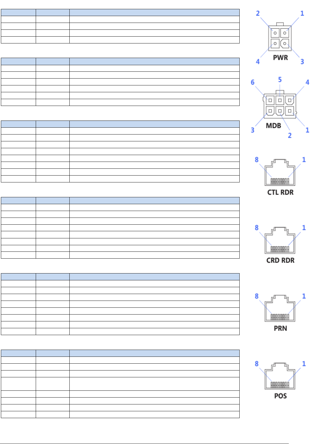
APPENDIX B - CONNECTOR PINOUTS ON UT430
PWR
Pin Signal Description
1 NC Not Connected
2 VS 12V DC Supply Voltage
3 GND Ground
4 GND Ground
MDB
Pin Signal Description
1 MDB-VS MDB Supply Voltage
2 GND Ground
3 WAKEUP MDB Bidirectional Wakeup
4 MDB-TX MDB Transmit (Output)
5 MDB-RX MDB Receive (Input)
6 MDB-GND MDB Isolated Ground (for MDB-TX and -RX)
CTL RDR
Pin Signal Description
1 NC Not Connected
2 EXCTL-VCC External Contactless 3.3V Supply Voltage
3 NC Not Connected
4 EXCTL-TX External Contactless Transmit (Output)
5 EXCTL-RX External Contactless Receive (Input)
6 GND Ground
7 EXCTL-DET External Contactless Detected (Input)
8 NC Not Connected
CRD RDR
Pin Signal Description
1 NC Not Connected
2 CR-TX External Card Reader Transmit (Output)
3 CR-RX External Card Reader Receive (Input)
4 NC Not Connected
5 GND Ground
6 CR-RTS External Card Reader Request To Send (Output)
7 CR-CTS External Card Reader Clear To Send (Input)
8 NC Not Connected
PRN
Pin Signal Description
1 NC Not Connected
2 PRN-TX External Printer Transmit (Output)
3 PRN-RX External Printer Receive (Input)
4 NC Not Connected
5 GND Ground
6 PRN-RTS External Printer Request To Send (Output)
7 PRN-CTS External Printer Clear To Send (Input)
8 NC Not Connected
POS
Pin Signal Description
1 NC Not Connected
2 POS-TX POS Transmit (Output)
3 POS-RX POS Receive (Input)
4 POS-VS
POS 12V Supply Voltage ** Required, if powering via serial port on
machine**
5 GND Ground
6 POS-RTS POS Request To Send (Output) **Optional**
7 POS-CTS POS Clear To Send (Input) **Optional**
8 NC Not Connected

227 Burwood Road,
Hawthorn, Victoria, Australia 3122
Office Phone: +61 3 8807 4400
Support Phone: +61 3 8807 4444
Support E-mail: support@questps.com.au