Quest Technical Sales and QTSHPWETH Wireless RS-485 Transceiver User Manual Rev 3
Quest Technical Sales and Marketing, Inc. Wireless RS-485 Transceiver Users Manual Rev 3
Users Manual Rev 3
IMPORTANT SAFETY INSTRUCTIONS
READ AND FOLLOW ALL INSTRUCTIONS
SAVE THESE INSTRUCTIONS
INSTALLATION GUIDE
HIGH POWER WIRELESS LINK KIT
FOR INTELLICENTER™, INTELLITOUCH® AND EASYTOUCH®
CONTROL SYSTEMS
High Power Wireless Link Kit Installation Guide
2 3
Technical Support
Phone: (800) 831-7133 - www.pentair.com
Contents
FCC Regulatory Safety Notice ...........................................................................3
High Power Wireless Link Kit Overview .............................................................4
High Power Wireless Link Kit Contents .............................................................. 4
High Power Wireless Link Indoor Transceiver LEDs and Connectors ................ 5
High Power Wireless Link For ScreenLogic Interface Systems ..................6
Mounting Indoor Transceiver ..........................................................................6
Mounting Outdoor Transceiver ....................................................................... 8
Connect Transceiver Cable to the RS-485 COM Port .....................................8
IntelliCenter Control System
(Replacing Existing Wireless Antenna with HPW Link) .......................13-14
IntelliCenter Control System
(Without an Existing Transceiver) ...........................................................13-16
P/N 523445 Rev. A 1/2019

High Power Wireless Link Kit Installation Guide
2 3
FCC Regulatory Safety Notice
FCC non-modification statement:
Changes or modifications not expressly approved by the party responsible for compliance
could void the user’s authority to operate the equipment.
FCC RF Exposure requirements:
Notice for High Power Wireless Link (FCC ID: 2AHWAQTSHPWETH -
HVIN/MODEL: HPW-WETHLINK: In order to comply with FCC/ISED RF Exposure
requirements, a minimum separation distance of 8 in (20 cm) must be maintained between the
equipment and all persons during normal operation.
Exigences de la FCC en matière d’exposition aux fréquences radio:
Remarquer: pour lien sans fil haute puissance (FCC ID: 2AHWAQTSHPWETH -
HVIN/MODEL: HPW-WETHLINK: Afin de respecter les exigences d’exposition RF de la FCC
/ ISED, une distance minimale de 20 cm doit être respectée entre l’appareil et toutes les
personnes en fonctionnement normal.
Canada - Innovation, Science and Economic Development (ISED)
(ISED: 21176-QTSHPWETH): The Control System and the High Power Wireless (HPW)
Link complies with RSS210 of ISED Canada (2019). Operation is subject to the following two
conditions: (1) this device may not cause interference, and (2) this device must accept any
interference, including interference that may cause undesired operation of the device.
This Class B digital apparatus complies with Innovation, Science and Economic Development
(ISED) Exempt RSSs. Operation is subject to the following: (1) This device may not cause
interference; and (2) This device must accept interference that may cause undesired operation
of the device.
Le dispositif est conforme à la licence Innovation, Science and Economic Development
(ISED) Canada. Le fonctionnement est soumis à la suivante. (1) Ce ne doit pas provoquer
d’interférences ; et (2) Cet appareil doit accepter les interférences qui peuvent causer un
mauvais fonctionnement de l’appareil.
Cet appareil numérique de classe B est conforme à la norme canadienne ISDE (RSP-100,
section 2.1) et Terminal Equipment Registrations (DC-01, Section 3.). Cet appareil numérique
de la classe B est conforme à la norme NMB-003 du Canada. Le terme «ISED» précédant
le numéro de certification / d’enregistrement signifie uniquement que les spécifications
techniques relatives à l’innovation, à la science et au développement économique ont été
respectées.
Instruction to user: The IntelliCenter™, EasyTouch® and IntelliTouch® Control System
High Power Wireless (HPW) Link has been tested and found to comply with the limits for a
Class B digital device, pursuant to Part 15 of the FCC Rules. These limits are designed to
provide reasonable protection against harmful interference in a residential installation. The
IntelliCenter, EasyTouch and IntelliTouch Control System High Power Wireless (HPW) Link
generates, uses and can radiate radio frequency energy and, if not installed and used in
accordance with the instructions, may cause harmful interference to radio communications.
However, there is no guarantee that interference will not occur in a particular installation. If
this device does cause harmful interference to radio or television reception, which can be
determined by switching the device off and on, the user is encouraged to try to correct the
interference by one or more of the following measures:
• Reorient or relocate the receiving antenna.
• Increase the separation between the equipment and receiver.
• Connect the equipment into an outlet on a circuit different from that to which
the receiver is connected.
• Consult the dealer or an experienced radio/TV technician for help.
Note: The user is cautioned that changes and modifications made to the IntelliCenter,
EasyTouch and IntelliTouch Control System without the approval of the manufacturer could
void the user’s authority to operate this equipment.
High Power Wireless Link Kit Installation Guide
4 5
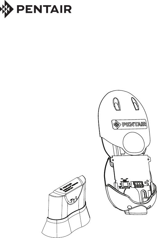
High Power Wireless Link Kit Overview
The High Power Wireless Link consists of an indoor and outdoor
902-928 MHz wireless transceiver. Note: The wireless transceivers ship
from the factory as a matched pair. The ID numbers on each transceiver
must be the same number to function correctly. If needed, the transceivers
must be replaced as a matched pair. For more information, call Customer
Support 800.831.7133.
Automation Control System: The High Power Wireless Link indoor and
outdoor transceiver provide a wireless connection between the Internet
and the IntelliCenter™, IntelliTouch® or EasyTouch® Control System Load
Center (or Power Center) located at the equipment pad which eliminates
hard wire connection from inside your home to the equipment pad.
Installation Guide
This Installation Guide provides installation instructions for the High Power
Wireless Link kit. For information about ScreenLogic Interface operation, refer
to the ScreenLogic Interface User’s Guide (P/N 520493).
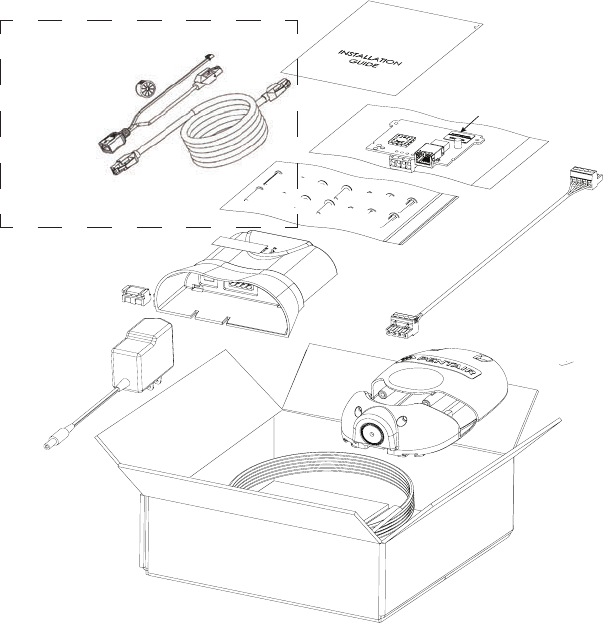
High Power Wireless Link Kit
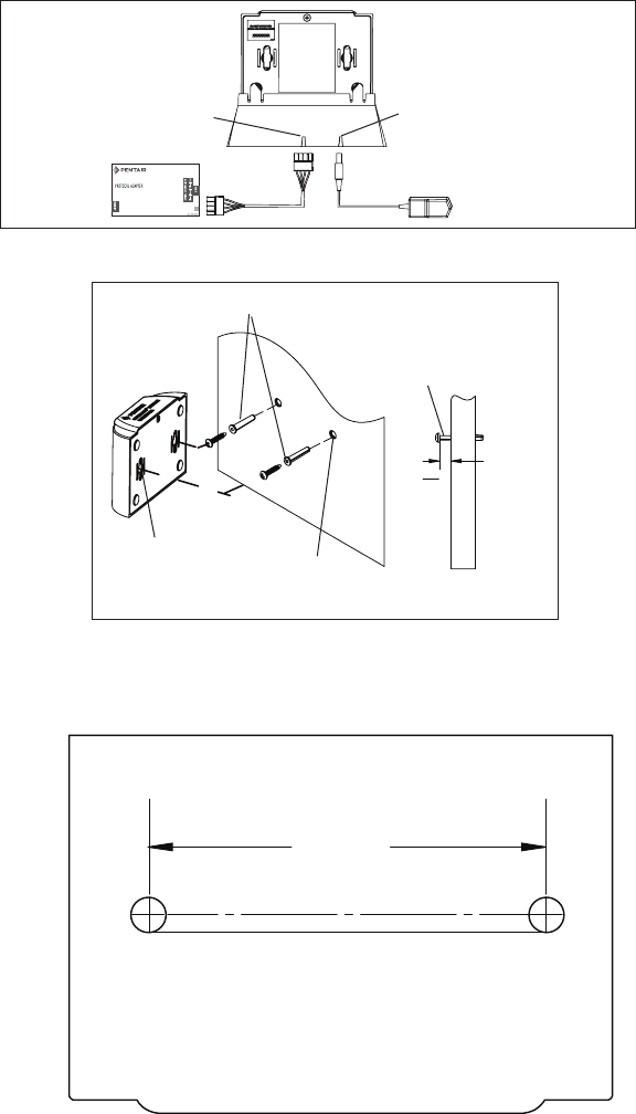
High Power Wireless Link Kit Contents
The following items show are included in the kit:
Note: ScreenLogic Interface Protocol Adapter and Cable (purchased separately)
Mounting hardware
(screws)
Outdoor
Transceiver
enclosure
Indoor transceiver
and base
Outdoor Cable
(white - 15 ft.)
NOTE (*): ID numbers
on Indoor and Outdoor
transceiver board must
match
Power Over Ethernet Module
(Outdoor hardware)
Cable (for connection to
ScreenLogic
®
Interface
Protocol Adapter
(purchased separately)
Ethernet Cable
(15 ft.)
Manual
Outdoor Transceiver
(Cable Restrainer)
AC Power Adapter
High Power Wireless
Link PoE/Ethernet Cable
Bundle (P/N 544425)
High Power Wireless Link Kit Installation Guide
4 5
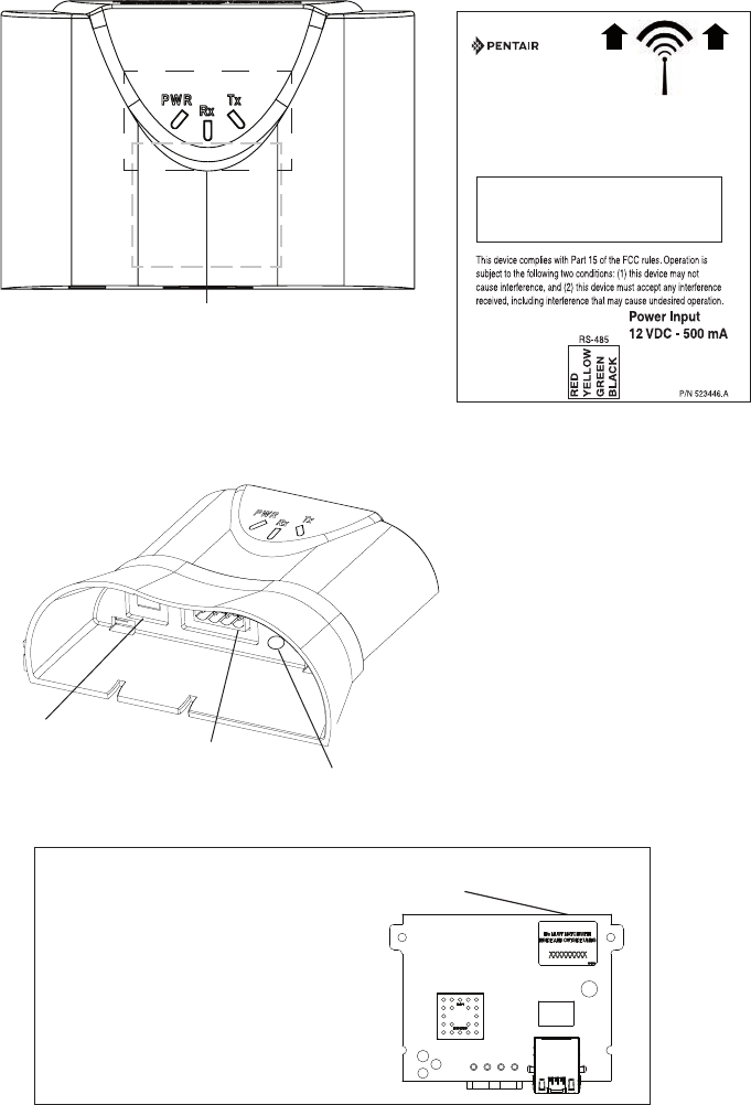
PWR: Green LED on: Power is on to the unit.
RX: Yellow LED indicates the unit is receiving data.
TX: Green LED indicates the unit is transmitting data.
ID number
(Outdoor transceiver)
IMPORTANT NOTICE: Be sure the
yellow ID label (8-digit ID number
XXXXXXXX) located on the front side
of the Indoor transceiver and the ID
number on the outdoor transceiver
circuit board are the same.
RS-485 Connector
(to Protocol Adapter,
ScreenLogic only)
High Power Wireless Link Indoor Transceiver LEDs and Connectors
High Power Wireless
Indoor Transceiver LEDs
RS-485 Connector
(to Protocol Adapter,
ScreenLogic only)
Ethernet Port
High Power
Wireless Indoor
Transceiver and
base
Power Plug
socket
2.16 in
1.75 in
Keep this side
clear of ALL
metal objects for
2 ft. (61 cm)
Model: HPW-WETHLINK
HVIN: HPW-WETHLINK
FCC ID: 2AHWAQTSHPWETH
ISED: 21176-QTSHPWETH
HIGH POWER
WIRELESS LINK
High Power Wireless Link Kit Installation Guide
6 7
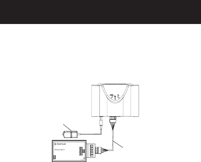
Connect the High Power Wireless (HPW) Indoor Transceiver to the ScreenLogic®
Interface Protocol Adapter as follow: See Figure 6 on page 12.
1. Using the provided 1 ft. RS-485 cable, connect one end of the cable
plug to the Protocol adapter and the other end to the HPW Link indoor
transceiver. The cable plugs are keyed for easy connection. See diagram
below.
2. Plug the 120 VAC Power Adapter into an AC grounded electrical outlet.
Plug the other end into the power socket on the HPW Link indoor
transceiver.
Wall Mount the HPW Indoor Transceiver (Figure 2 and Figure 3)Mount the
Mount the HPW Indoor Transceiver on an indoor wall as follows:
1. Cut out the wall mounting template from the next page. Place the template
on an indoor flat surface or wall and mark the two screw hole positions.
2. Drill two holes (0.223 in) 2-1/2 inches apart as shown on the template (see
Figure 3 on next page).
3. Insert the wall plugs into both wall screw holes.
4. Insert the screws into the wall plug. Don’t insert the screws all the way into
the wall, leave about 1/16 in for the wireless transceiver to hang on the
head of the screws (see Figure 2 on next page).
5. Mount the wireless transceiver onto both screw heads.
Base/Desk Mount the HPW Indoor Transceiver (Figure 1 on page 7)
Mount the HPW Indoor Transceiver in its base as follows:
1. Insert the power cable into the base of the HPW Link Indoor transceiver
base. Fasten the cable into the cradle slot (see Figure 1 on page 7).
2. Insert the connection cable into the base of the transceiver cradle. Fasten
the cable into the cradle slot (see Figure 1 on next page).
3. Place the transceiver and base on a table or desk. Note: Keep the
transceiver clear of all objects for two feet. Note: Do not place the
transceiver on the floor or behind a desk.
Connecting the HPW Indoor Transceiver and Protocol Adapter
SCREENLOGIC INTERFACE
®
Connection cable (1 ft)
(provided in kit)
120 VAC
Power Adapter
HPW Indoor
Transceiver
Protocol
Adapter
High Power Wireless Link For ScreenLogic
Interface Systems
High Power Wireless Link Kit Installation Guide
6 7
Wall Mount the HPW Indoor Transceiver (Continued)
2½ in
Figure 3: Wall Mount Template for HPW Link Indoor Transceiver
HPW Link Indoor Transceiver Mounting Screws Location
Figure 2: Wall Mount the Indoor Wireless Transceiver
Figure 1: Cradle/Desk Mount the HPW Indoor Transceiver
Hang module
on screw head
(approx. 1/16 in
from wall surface)
1
16
"
(0.41 cm)
Mounting screw/plug (2x)
Screw hole (x2)
Wall screw
hole (2x)
Secure AC power
cable in slot in base
Secure
communication
cable in slot in base
120 VAC
power adapter
Protocol adapter
SCREENLOGIC INTERFACE
®
High Power Wireless Link Kit Installation Guide
8 9
Mounting and Connecting the Outdoor High Power Wireless (HPW)
Transceiver to the Automation Control System Load Center
The following describes how to mount and connect the HPW Link outdoor
transceiver to an IntelliTouch® or EasyTouch® Automation Control System
Load Center or Power Center. See Figure 6 on page 12.
Mounting the HPW Outdoor Transceiver
The HPW outdoor transceiver is a two-way radio device with an attached
antenna that communicates with the automation control system via a 15 ft.
four-conductor RS-485 communication cable.
HPW Outdoor Transceiver mounting location: Choose a convenient location
on a flat vertical surface near the Load Center at a minimum of 5 ft above
ground level to optimize the transmit and receive operating range. For optimum
performance position the HPW Outdoor transceiver with an unobstructed line-
of-sight propagation between the HPW Indoor and Outdoor transceiver.
1. Position the back plate against the mounting surface so that the
transceiver is oriented in an upright position with the antenna
pointing upwards. Use a pencil to mark the four mounting points.
Drill four 3/16 in. diameter holes into the mounting surface and
insert the four plastic anchors provided in the kit.
Note: To avoid signal interference, mount the transceiver
a minimum of 10 feet away from the load center, any metal
surface/structure, or air blower located in the immediate area
of the equipment pad.
2. Position the back plate over the mounting points and secure it with
the four mounting screws provided in the kit.
3. Carefully position the transceiver circuit board into the mounted
back plate. Route the communication cable wire up through the
lower exit hole at the bottom of the back plate. Carefully pull the
communication cable out the lower hole and position the circuit
board in the back plate.
4. Proceed to Connect the HPW Outdoor Transceiver Cable to the
RS-485 COM Port on Automation Control System on the next
page.
5. Slide the case over the circuit board and antenna into the back
plate. Secure the circuit board in the case using the two retaining
screws.
High Power Wireless Link Kit Installation Guide
8 9
Figure 4. HPW Link Outdoor Transceiver
Case
Transceiver case
retaining screws (x2)
Back plate for
mounting circuit
board
HPW Link Outdoor Transceiver
circuit board
RS-485 - Connect
4-conductor communication
cable to terminal screws.
RS-485
COM PORT (RS-485)
screw terminal connector
on IntelliTouch® or
EasyTouch® Control System
BLK
RED
YEL
GRN
BLK (GND - PIN 1)
GRN (- DT - PIN 2)
YEL (+ DT - PIN 3)
RED (15 V - PIN 4)
HPW Outdoor
Transceiver
circuit board
Connect the HPW Link Outdoor Transceiver Cable to the
RS-485 COM Port on Automation Control System
WARNING Switch OFF the main power to the Load Center
before making any connections.
1. Switch OFF the AC power to the enclosure at the main house panel
circuit breaker.
2. Connect the four conductor connection cable to the screw terminal
on the HPW Outdoor Transceiver circuit board as shown below in
Figure 4.
Continue to next page.
High Power Wireless Link Kit Installation Guide
10 11
WARNING Switch OFF the main power to the Load Center
before making any connections.
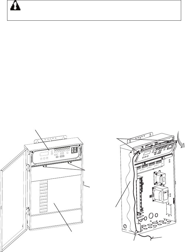
3. Unlatch the front door latch and open the front door. Remove
the two retaining screws from the High-Voltage Cover Panel and
remove the panel. See Figure 5 below.
4. Loosen the two retaining screws securing from the top edge of
the Outdoor Control Panel. Fold down the Outdoor Control Panel
to access the circuit board sockets connectors for the electrical
connections. Remove the panel from the enclosure.
5. Route the four conductor transceiver connection cable into the
lower plastic grommet, up through the low voltage raceway to the
system circuit board.
Figure 5. IntelliTouch® or EasyTouch® Control System Load Center
Retaining
screws
HIGH -VOLTAGE
FRONT COVER
PANEL
Outdoor
Control Panel
retaining
screw (x2)
Outdoor
transceiver|
communication
cable
(connect to
COM port)
Outdoor Control Panel
Grommet
(under side
of Load
Center
Inside Low
voltage race-
way
Latch
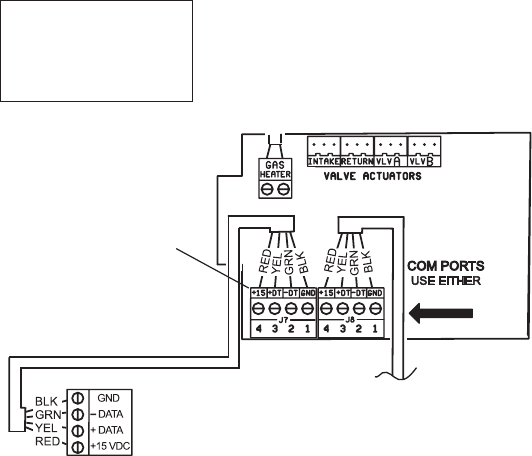
Connect the HPW Outdoor Transceiver Cable to the
RS-485 COM Port on Automation Control System (Continued)
High Power Wireless Link Kit Installation Guide
10 11
6. Strip the leads of the communication cable wires back ¼ in. Insert
the wires into the connector screw terminals. Using a small flat-
blade screwdriver, secure the wires with the COM PORT (J7/J8)
terminal screws. Note: Multiple wires may be inserted into a single
screw terminal. Be sure to match the color-coding of the wires:
Pin 4 - Red = +15 VDC
Pin 3 - Yellow = +DT
Pin 2 - Green = -DT
Pin 1 - Black = GND
IntelliTouch® (J7/J8) or
EasyTouch® Control
System COM Ports
(J20) screw terminal
connector
Note: Multiple wires may be
inserted into a single screw
COM PORT terminal. However,
this can cause an intermittent
connection. Note: For additional
COM ports, an optional Serial
COM Port Expansion Board (P/N
520818) can be installed in the
low voltage compartment.
7. After the communication cable connection has been completed;
close the Outdoor Control Panel and tighten the two retaining
screws. Reinstall the High Voltage Panel: Insert the panel’s three
tabs into the lower slots on the enclosure. Secure the panel with the
two (2) retaining screws. Close the front door and secure it with the
latch.
8. Switch ON AC power to the Load Center.
9. After the Power Center is powered up the HPW Link outdoor
transceiver will automatically synchronize with the system and will
be ready for operation. Note: The initial connection can take up
to 2-3 minutes.
High Power Wireless Link Kit Installation Guide
12 13
1234
WAN
RJ45
Wireless Router
EasyTouch or IntelliTouch
Control System Load Center
ScreenLogic2
program
In
t
t
e
ernet
Intellicenter.com
(home user)
RJ11
DSL or
Cable Modem
RJ11 for DSL
Coax for Cable
LAN PORTS
Ethernet (RJ45 - CAT 5)
to Wireless Router
LAN Port
AC Power Adapter
(Indoor wall outlet)
RJ45
SCREENLOGIC INTERFACE
®
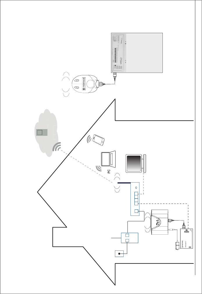
Figure 6. High Power Wirless Link to EasyTouch or IntelliTouch
Control System Connection Diagram
Ethernet
RS-485
900 MHz Wireless
Link to outdoor
Transceiver
RS-485
900 MHz Wireless
Link to indoor
Transceiver

High Power Wireless Link Kit Installation Guide
12 13
INTELLICENTER® CONTROL SYSTEM
(Replacing Existing Wireless Antenna with High
Power Wireless Link
WARNING Switch OFF the main power to the Load Center
before making any connections.
1. Switch OFF the AC power to the enclosure at the main house panel circuit
breaker.
2. Unlatch the front door latch and open the front door. Remove the two
retaining screws from the High-Voltage Cover Panel and remove the panel.
See Figure 5 on page 10.
3. Loosen the two retaining screws securing from the top edge of the Outdoor
Control Panel. Fold down the Outdoor Control Panel to access the circuit
board sockets connectors for the electrical connections. Remove the panel
from the enclosure (see illustration below).
4. Disconnect the Ethernet cable from the existing transceiver. and
remove the transceiver: To access the transceiver Ethernet port, remove
the rear bottom panel from the antenna assembly. From the front of the
antenna assembly, press down on the rear bottom panel clip to release it
from the antenna assembly. See Figure 7 on page 14.
5. Remove the two screws securing the existing transceiver and remove the
transceiver from its mounting position.
6. Connect the HPW Link Outdoor Transceiver: Connect the Ethernet cable
(from the IntelliCenter Control System Power Module) to the Ethernet port
on the HPW Link outdoor transceiver circuit board.
7. Mount and secure the HPW Link outdoor transceiver in the same location
as the existing transceiver. Secure the transceiver in place with the two
screws.
8. Slide case up over the circuit board and antenna into the back plate.
Secure the circuit board in the case using the two retaining screws.
9. Home Wireless Router Location: Connect Ethernet Cable (cat5) to
Indoor HPW Link Transceiver and to Home Wireless Router (See
Figure 8 on page 15): Connect the Ethernet cable (provided) to a port on
the home wireless router. Connect the other end of the Ethernet cable to
the HPW Link indoor transceiver.
10. Indoor Power Module Connection: Connect the AC Power Adapter plug
into the Power Module DC-IN socket and the plug other end into a AC wall
outlet.
System Start-Up
Refer to the IntelliCenter Control System using the step-by-step Setup Wizard.
For more information refer to the IntelliCenter™ Control System User’s Guide
(P/N 522990).
High Power Wireless Link Kit Installation Guide
14 15
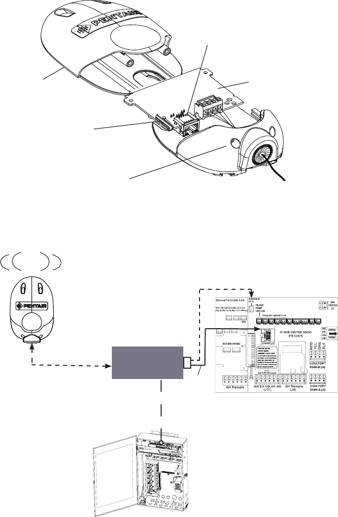
HPW Link Outdoor Transceiver
Case
Transceiver case
retaining screws (x2)
Back plate for
mounting circuit
board
HPW Outdoor
Transceiver
circuit board
Ethernet Port
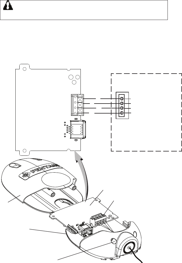
AUX 5 AUX 6
AUX 7 AUX 8 AUX 9
From
Ethernet
Port (J14) IntelliCenter™ Control
System main circuit
board
2-Pin 24 VDC Socket
(to Power Module)
Power
Cable
Ethernet (Cat5) Cable
(from HPW transceiver Place the
Power Module
in the low voltage
compartment
To Ethernet Port on
IntelliCenter Circuit Board
High Power
Wireless Link
Outdoor
Transceiver
Figure 7. Power Module Connection
Power Module

High Power Wireless Link Kit Installation Guide
14 15
INTELLICENTER CONTROL SYSTEM
(Without an Existing Transceiver)
WARNING Switch OFF the main power to the Load Center
before making any connections.
1. Switch OFF the AC power to the enclosure at the main house panel circuit
breaker.
2. Unlatch the front door latch and open the front door. Remove the two
retaining screws from the High-Voltage Cover Panel and remove the panel.
See page 11 for connection diagram.
3. Loosen the two retaining screws securing from the top edge of the
Outdoor Control Panel. Fold down the Outdoor Control Panel to access the
circuit board sockets connectors for the electrical connections. Remove the
panel from the enclosure (see illustration below). See Figure 5 on page 10.
4. Power Module Ethernet Cable Connection: Connect the short Ethernet
1 ft cable (provided in kit) into the Ethernet port on the IntelliCenter Control
System Outdoor Control Panel circuit board. Connect the other end into
the LAN port on the Power Module. See Figure 7 on page 14.
5. Connect the Ethernet cable (15 ft cable provided in kit) into the LAN port
on the Power Module. Route the cable down the Load Center raceway and
out of the lower opening of the Load Center or Power Center.
6. Power Module Power Connection: Connect the 24VDC connector
into the Power Module DC-IN socket and the plug other end into the
IntelliCenter Control System Outdoor Control Panel circuit board. See
Figure 7 on page 14.
7. Route the Ethernet cable (15 ft cable provided) to the HPW Link outdoor
transceiver. Remove the knockout on the bottom of the transceiver and
insert the Hole Plug into the opening. Route the cable through the opening
in the plug.
8. Mount the HPW Link Outdoor Transceiver: Mount the HPW outdoor
transceiver to a vertical flat surface near the Load Center. Secure the
transceiver in place with the two screws.
9. Remove the two screw from the HPW antenna transceiver case. Slide the
case down to access the Ethernet port on the circuit board.
10. Slide case up over the circuit board and antenna into the back plate.
Secure the circuit board in the case using the two retaining screws.
11. Home Wireless Router Location: Connect Ethernet Cable (cat5) to
Indoor HPW Link Transceiver and to Home Wireless Router (See
Figure 8 on page 15): Connect the Ethernet cable (provided) to a port on
the home wireless router. Connect the other end of the Ethernet cable to
the HPW Link indoor transceiver.
12. Power Module Connection: Connect the AC Power Adapter plug into the
Power Module DC-IN socket and the plug other end into a AC wall outlet.

High Power Wireless Link Kit Installation Guide
16 16
1620 HAWKINS AVE., SANFORD, NC 27330 • (919) 566-8000
10951 WEST LOS ANGELES AVE., MOORPARK, CA 93021 • (805) 553-5000
WWW.PENTAIR.COM
All Pentair trademarks and logos are owned by Pentair or by one of its global affiliates. ScreenLogic®,
EasyTouch® and IntelliTouch® are trademarks and/or registered trademarks of Pentair Water Pool
and Spa, Inc. and/or its affiliated companies in the United States and/ or other countries. iPhone®
is a registered trademark of Apple Corporation. Unless expressly noted, names and brands of third
parties that may be used in this document are not used to indicate an affiliation or endorsement
between the owners of these names and brands and Pentair Water Pool and Spa, Inc. Those names
and brands may be the trademarks or registered trademarks of those third parties. Because we are
continuously improving our products and services, Pentair reserves the right to change specifications
without prior notice. Pentair is an equal opportunity employer.
© 2019 Pentair Water Pool and Spa, Inc. All rights reserved.
This document is subject to change without notice.
P/N 523445 1/2019
*523445*