R F Technologies 30011534001 User Manual Antenna Install peter p65
RF Technologies Inc Antenna Install peter p65
Contents
- 1. Hardware Overview
- 2. Cell Controller Manual
- 3. Antenna Manual
Antenna Manual
A20-EC Antenna
Installation Manual
© Copyright 1999, PinPoint Corporation. All rights reserved.
Warnings ...................................... 2
Included In This Package ............. 3
About Antennas ............................ 4
Placement ..................................... 5
Mounting............................................6
Installing ...................................... 7
Technical Specification ................ 7
Warnings
The 3D-iD Antenna is intended for indoor use only. Use of the Antenna
outdoors can cause damage to its internal components. Contact your
PinPoint sales representative for details regarding outdoor use of the
3D-iD system.
Do not mount the Antenna in places that are excessively humid or
where it is likely to get wet.
When placing your antenna, keep in mind that metallic objects, dense
walls, microwave ovens and other obstacles can alter radio signals,
limiting the Antennas effectiveness. See your certified system integrator
for proper Antenna placement.
The antenna must be installed so that there is at least a 6 inch gap
between it and any possible contact with people. Failure to install it in
this fashion may invalidate the users license to operate this product.

Included In This Package
1 Antenna
1 Antenna mount, including:
1 Base plate
1 Mount post
1 Mounting Plate
2 Screws (1/2)
2 Washers
1 Allen wrench
1 Antenna card (optional)
CLOSE-UP OF ANTENNA AND MOUNT (ATTACHED)
About Antennas
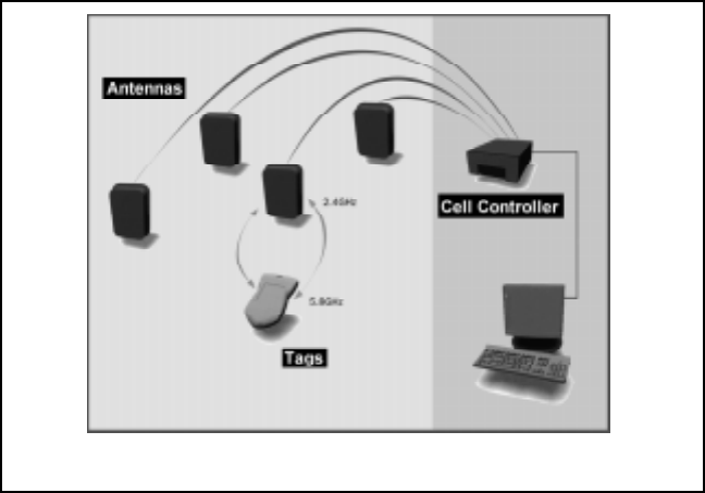
The 3D-iD Antennas are attached to the Cell Controller and are DC
powered by special, low-loss Coaxial Cables. Up to sixteen (16)
Antennas may be attached to a single Cell Controller. The Cell Con-
troller generates a 2.44GHzradio signal which it sends to the Antenna
via the Coaxial Cable connecting them. The Antenna broadcasts the
signals to the surrounding area with an ellipsoidal radiation pattern. Any
Tags that are within range recieve the signal, add their serial number,
and transflect the signal back to the antenna at 5.77GHz. The Antenna
then sends the response back down to the Cell Controller which
measures the delay between when the signal was sent and when it was
received, thus generating Tag-Antenna Distance (TAD) data.
Diagram of Cell Controller, Tags, Antennas and the Software system.
The Antennas come with a mount allowing them to be attached to a flat
surface, such as a wall. For other mounting configurations, please
contact your certified 3D-iD system integrator.
Antenna Placement Tips
The exact location of Antennas will be determined by a certified 3D-iD
system integrator. The Antennas will be positioned to optimize the
locating capability of the system in accordance with the requiremetns
set forth by the customer.
The Antennas must be placed within sufficient distance of their corre-
sponding Cell Controller (100 feet). The Coaxial Cables connecting an
Antenna to its Cell Controller must not be stretched, kinked or other-
wise damaged during Antenna installation.
The Antennas should not be placed very close to metal walls, micro-
wave ovens or other objects that will hinder their performance. Metallic
objects and dense walls can alter the radiation pattern of the Antennas.
The Antennas should be mounted in locations that prevents accidental
contact or intentional destruction. Mounting the Antennas near ceilings
and out of reach is strongly recommended.
The antenna must be installed so that there is at least a 6 inch gap
between it and any possible contact with people. Failure to install it in
this fashion may invalidate the users license to operate this product.

Mounting the Antenna
The Antenna mount is intended for flat walls of varying construction.
Please contact your certified 3D-iD system integrator for other mount-
ing applications.
1) Using the appropriate hardware, securely attach the circular base-
plate of the mount to a flat surface in the desired location. Ensure
sufficient clearance is left between the baseplate and any nearby ceilings
and walls to allow for full adjustment of the Antenna once it is mounted.
2) Attach the mounts post to the base plate. Tighten the lock nut with a
pliers.
3) Prepare the Antenna by attaching the small, rectangular mounting
plate to the back of the Antenna with the two (2) included 1/2 screws
and washers.
4) Attach Antenna to mount by aligning the mounting plate on the
Antenna with the threaded bolt at the end of the post and rotating the
Antenna until it stops. Tighten the locknuts to secure the Antenna.
PICTURES OF 1) BASE PLATE AND POST IN WALL
2) BACK OF ANTENNA WITH MOUNTING PLATE

1) Loosen both set screws on the mount with the enclosed wrench.
Align the Antenna so it is oriented in the direction indicated by the
system integrator. Tighten both set screws
Technical Specification
2) Attach the Antenna to its appropriate Coaxial Cable. For tension
relief, insert a tie wrap through theguide on the back of the antenna and
secure the Coaxial Cable with the tie-wrap.
Installing the Antenna
PICTURE OF MOUNTED ANTENNA
Frequency: Tx: 2442 + 83.5 MHz
Rx: 5800 + 150 MHz
Power: 12 V DC (supplied from coaxial cable)
Radiation Pattern: Ellipto-conical (62° azimuth, 32° elevation)
Dimensions: 10 x 7x 2
Environment: -20°C 40°C (operating range)
5% - 95% humidity, no condensation
See Cell Controller/Antenna Data Sheets for details
PinPoint Corporation
One Oak Park Bedford, MA 01730
http://www.pinpointco.com
phone: 781-687-9720
fax: 781-687-9730