R F Technologies SP2FSZ24 Nurse Call Pendant Transmitter User Manual manual
R F Technologies Inc Nurse Call Pendant Transmitter manual
manual

9600 Series Wireless
Call System
Hardware Installation Guide
PN 0510-1078-D
<

<
9600 Series Wireless
Call System
Hardware Installation Guide
PN 0510-1078-D
Release Date: 02/23/10
Users must read this guide before using the product.
<

Copyright 2009, 2010 by RF Technologies, Inc.
All Rights Reserved. No Part of this work may be reproduced or copied in any form or by
any means without written permission from RF Technologies, Inc.
Conformsto
ULStd.294
(3048736)
Important Warnings
It is important for your facility to implement and enforce the following WARNINGS in order to keep all equipment functioning
properly. Disregarding the information and instructions in this document is considered abnormal use and may result in injury or
system failure.
WARNING
ACCESSORIES (SUPPLIES)—To ensure patient safety and proper operation of equipment,
use only parts and accessories manufactured or recommended by RF Technologies, Inc. Parts
and accessories not manufactured or recommended by RF Technologies, Inc. may not meet the
requirements of the applicable safety and performance standards.
Failure to use the components and supplies specified by RF Technologies, Inc. may result in
equipment and/or system failure.
WARNING
EXPLOSION HAZARD—This device should not be used in the presence of flammable gas mixtures. It
should also not be used in oxygen enriched atmospheres.
WARNING
INSTALLATION AND CONFIGURATION—It is the responsibility of the facility to follow the
installation instructions carefully, as outlined in the applicable system guides, and to use the components
and supplies specified by RF Technologies, Inc. for all installations.
Failure to use the components and supplies specified by RF Technologies, Inc. may result
in equipment and/or system failure.
WARNING
INSTRUCTIONS FOR SET UP AND USE—It is the responsibility of the facility to follow the
instructions for set up and use carefully, as outlined in this manual, and to use the components and
supplies specified by RF Technologies, Inc. for set up and use. Do not attempt to use extension cords or
other equipment not supplied by RF Technologies, Inc.
Failure to use the components and supplies specified by RF Technologies, Inc. may result in
equipment and/or system failure.
WARNING
PATIENT GENERATED ALARMS—Do not rely exclusively on patient generated alarms for
patient care and safety. The alarm function of equipment in the possession of patients must be
verified periodically and regular patient surveillance is recommended.
WARNING
PATIENT MONITORING—The most reliable method of patient monitoring combines close
personal surveillance with correct operation of monitoring equipment. It is the responsibility of
the facility to periodically check on patients in possession of RF Technologies, Inc.'s
equipment (i.e. Pendants, Pull Cords, Control Units) to mitigate risk of inappropriate use of
equipment or strangulation and stumbling hazards from cables and cords
WARNING
PRODUCT WARRANTIES—Failure to follow the Warnings and Cautions in this guide voids
any and all Product Warranties
WARNING
STATIC DISCHARGE—Do not touch the conductor portion of any conductor or port.
Damage to the device may result.
WARNING
STRANGULATIONS AND TRIPPING HAZARD—Due to the possibility of strangulation, all cables
and cords should be routed away from the patient’s throat. Cables and cords must be routed in a way to
prevent tripping hazards.
WARNING
SYSTEM INSPECTION—It is the responsibility of the facility to establish and facilitate a
regular inspection schedule for your system. RF Technologies, Inc. recommend quarterly
inspections of your system for safety and performance by a qualified RF Technologies, Inc.
representative.
To arrange for a quarterly inspection by RF Technologies, Inc., call our Technical Support
Department at (800)-669-9946 or (262) 790-1771.
Failure to provide regular inspection of these products may result in equipment and/or system
failure.
WARNING
SYSTEM MAINTENANCE AND TESTING—It is the responsibility of the facility to
establish and facilitate a regular maintenance schedule for your system, as outlined in the
applicable system guides. This includes regular inspection, testing, and cleaning. RF
Technologies, Inc. recommend monthly maintenance and testing of your system. It is also
recommended that your facility keep records of maintenance and test completions.
Failure to provide regular maintenance and testing of these products may result in equipment
and/or system failure.
Bio-Incompatibility Notice
Do not use Pendants with people that have sensitivities or allergies to device materials. The device materials include
Acrylonitrile butadiene styrene (ABS), Silicon Rubber and Neoprene
WARNING
SYSTEM WIRING—All permanent supply connections must be done in accordance with
National Electric Code, NFPA 70.
WARNING
USER TRAINING—Only users who have received adequate training on the use of the system, as
outlined in this manual, should use the system. It is the responsibility of the facility to ensure all users
have been trained.
Failure to adequately train employees may cause system failure due to user error. In addition,
incorrect use of the equipment may also result in system failure.
WARNING
WORN OR DAMAGED PARTS—If the control unit pads or cables are worn or damaged, you must
have the product serviced. For more information, see the section entitled “Service and Return.”
WARNING
All RF Technologies transmitters, pendants and banding material “PRODUCT” have been
determined to be MR Unsafe as defined by ASTM F 2503-05. Use of “PRODUCT” in a
Magnetic Resonance Imaging system will cause injury to patients and staff, MR system
malfunction or “PRODUCT” malfunction. Do not bring “PRODUCT” into the MR system
area and follow your facilities policies to classify and label “PRODUCT” as MR Unsafe.
CAUTION
DISPOSAL—At the end of their service life the products described in this manual, as well as
accessories (i.e. lithium batteries, banding material, disposable pads, etc.), must be disposed of
in compliance with all applicable federal, state and local guidelines regulating the disposal of
products containing potential environmental contaminants. Dispose of the packaging material
by observing the applicable waste control regulations.
Compliance
Federal Communication Commission (FCC)
Compliance
This device complies with Part 15 of the FCC Rules. Operation is subject to the following two conditions: (1) this device
may not cause harmful interference, and (2) this device must accept any interference received, including interference that
may cause undesired operation of the device.
This equipment generates, uses, and can radiate radio frequency energy and, if not installed and used in accordance with
the instruction manual, may cause harmful interference to radio communications. Operation of this equipment in a
residential area is likely to cause harmful interference in which case the user will be required to correct the interference at
his own expense. Changes or modifications not expressly approved by the party responsible for compliance voids the
user’s authority to operate the equipment.
FCC and IC Radiation Exposure Statement for Mobile
Devices
(For the Pull Cord model 0800-0285 and model 0800-0317; Universal Transceiver model 0800-0301, which covers part
numbers 0800-0303 and 0800-0304; Extended Range Router model 0800-0351 and model 0800-0354; Router model
0800-0364; Asset Transceivers model 0800-0286 and model 0800-0302 and Motion Control Unit model 0800-0350)
This equipment complies with FCC and IC radiation exposure limits set forth for an uncontrolled environment. This
equipment should be installed and operated with minimum distance 20cm between the radiator and your body. This
transceiver must not be co-located or operating in conjunction with any other antenna or transceiver.
FCC and IC Radiation Exposure Statement for Portable
Devices
(For the Pendant Transceivers model 0800-0288 and model 0800-0349; Call Pendant model 0800-0375; Care Manager
model 9600-0500)
This equipment complies with FCC and IC radiation exposure limits set forth for an uncontrolled environment. This
equipment is in direct contact with the body of the user under normal operating conditions. This transceiver must not be
co-located or operating in conjunction with any other antenna or transceiver.
Industry Canada Compliance
Changes or modifications not expressly approved by RF Technologies could void the user’s authority to operate the
equipment. The Term “IC” before the radio certification number only signifies that Industry Canada technical
specifications were met.
Operation is subject to the following two conditions: (1) this device may not cause harmful interference, and (2) this
device must accept any interference received, including interference that may cause undesired operation of the device.
This device has been designed to operate with the antennas listed below, and having a maximum gain of 3dBi. Antennas
not included in this list or having a gain greater than 3dBi are strictly prohibited for use with this device. The required
antenna impedance is 50 ohms. Acceptable antennas are PCB antennas in all cases of the Router which uses a 2.4 GHz 1/
2 wave RP-SMA.
To reduce potential radio interference to other users, the antenna type and its gain should be so chosen that the equivalent
isotropically radiated power (e.i.r.p.) is not more than that permitted for successful communication.

9600 Series Wireless Call System (0510-1078-D) - Hardware Installation Guide i
Contents
Preface . . . . . . . . . . . . . . . . . . . . . . . . . . . . . . . . . . . . . . . . . 1
Introduction . . . . . . . . . . . . . . . . . . . . . . . . . . . . . . . . . . . . . . . . . . . . . . . . . .1
About this Guide. . . . . . . . . . . . . . . . . . . . . . . . . . . . . . . . . . . . . . . . . . . . . . .1
Additional Detailed Documentation . . . . . . . . . . . . . . . . . . . . . . . . . . . . . . 2
Contact Information . . . . . . . . . . . . . . . . . . . . . . . . . . . . . . . . . . . . . . . . . . . 2
Product Warranty . . . . . . . . . . . . . . . . . . . . . . . . . . . . . . . . . . . . . . . . . . . . . 2
Chapter 1
Installing Hardware Components . . . . . . . . . . . . . . . . . . . 3
Introduction . . . . . . . . . . . . . . . . . . . . . . . . . . . . . . . . . . . . . . . . . . . . . . . . . 3
Installation Checklist . . . . . . . . . . . . . . . . . . . . . . . . . . . . . . . . . . . . . . . . . . 3
Installing Components . . . . . . . . . . . . . . . . . . . . . . . . . . . . . . . . . . . . . . . . . 4
Install the Central Server . . . . . . . . . . . . . . . . . . . . . . . . . . . . . . . . . . . . . . . . . .4
Install the Gateway . . . . . . . . . . . . . . . . . . . . . . . . . . . . . . . . . . . . . . . . . . . . . . .5
Install Routers . . . . . . . . . . . . . . . . . . . . . . . . . . . . . . . . . . . . . . . . . . . . . . . . . . .7
Place a Pendant into Survey Mode . . . . . . . . . . . . . . . . . . . . . . . . . . . . . . . . . . . . . . . 8
Determine Placement of Routers . . . . . . . . . . . . . . . . . . . . . . . . . . . . . . . . . . . . . . . . . 9
Quick Look Router. . . . . . . . . . . . . . . . . . . . . . . . . . . . . . . . . . . . . . . . . . . . . . . . . . . 10
Gateway/Router Reset Button . . . . . . . . . . . . . . . . . . . . . . . . . . . . . . . . . . . . . . . . . . 12
LED Sequence . . . . . . . . . . . . . . . . . . . . . . . . . . . . . . . . . . . . . . . . . . . . . . . . . . . . . . 13
Gateway/Router Channel Default . . . . . . . . . . . . . . . . . . . . . . . . . . . . . . . . . . . . . . . 13
Additional Gateway/Router Installation . . . . . . . . . . . . . . . . . . . . . . . . . . . . .14
Changing Channels . . . . . . . . . . . . . . . . . . . . . . . . . . . . . . . . . . . . . . . . . . . . . . . . . . 15
Router Depth . . . . . . . . . . . . . . . . . . . . . . . . . . . . . . . . . . . . . . . . . . . . . . . . . . . . . . . 17
Rebuild Subnet on Scanned Devices . . . . . . . . . . . . . . . . . . . . . . . . . . . . . . . . . . . . . 18
Scan Devices . . . . . . . . . . . . . . . . . . . . . . . . . . . . . . . . . . . . . . . . . . . . . . . . . . . . . . . 19

Contents
ii 9600 Series Wireless Call System (0510-1078-D) - Hardware Installation Guide
Chapter 2
Installing Transceiver Devices . . . . . . . . . . . . . . . . . . . . . 21
Introduction . . . . . . . . . . . . . . . . . . . . . . . . . . . . . . . . . . . . . . . . . . . . . . . . .21
Transceiver Devices . . . . . . . . . . . . . . . . . . . . . . . . . . . . . . . . . . . . . . . . . . . . .21
LED Light Indicator. . . . . . . . . . . . . . . . . . . . . . . . . . . . . . . . . . . . . . . . . . . . .22
Installing Transceiver Devices. . . . . . . . . . . . . . . . . . . . . . . . . . . . . . . . . . .22
Pull Cords/Emergency Call . . . . . . . . . . . . . . . . . . . . . . . . . . . . . . . . . . . . . . .22
Check-in Pull Cord. . . . . . . . . . . . . . . . . . . . . . . . . . . . . . . . . . . . . . . . . . . . . . . . . . . 23
Pull Cord Transceiver with Extended Battery Pack . . . . . . . . . . . . . . . . . . . .24
Wall Mount Emergency Call . . . . . . . . . . . . . . . . . . . . . . . . . . . . . . . . . . . . . .27
Universal Transceiver . . . . . . . . . . . . . . . . . . . . . . . . . . . . . . . . . . . . . . . . . . . .29
Tamper . . . . . . . . . . . . . . . . . . . . . . . . . . . . . . . . . . . . . . . . . . . . . . . . . . . . . . . . . . . . 29
Nurse Call . . . . . . . . . . . . . . . . . . . . . . . . . . . . . . . . . . . . . . . . . . . . . . . . . . . . .32
Door/Window Transceiver . . . . . . . . . . . . . . . . . . . . . . . . . . . . . . . . . . . . . . .34
Door/Window Transceiver with Reset Button. . . . . . . . . . . . . . . . . . . . . . . . . . . . . . 36
PIR Sensor. . . . . . . . . . . . . . . . . . . . . . . . . . . . . . . . . . . . . . . . . . . . . . . . . . . . .37
Smoke Detector . . . . . . . . . . . . . . . . . . . . . . . . . . . . . . . . . . . . . . . . . . . . . . . .39
Pendant Transceivers . . . . . . . . . . . . . . . . . . . . . . . . . . . . . . . . . . . . . . . . . . . .40
Activate the Battery . . . . . . . . . . . . . . . . . . . . . . . . . . . . . . . . . . . . . . . . . . . . . . . . . . 40
Set up the Pendant . . . . . . . . . . . . . . . . . . . . . . . . . . . . . . . . . . . . . . . . . . . . . . . . . . . 40
Reset the Pendant. . . . . . . . . . . . . . . . . . . . . . . . . . . . . . . . . . . . . . . . . . . . . . . . . . . . 41
Verify the Pendant Appears in the System . . . . . . . . . . . . . . . . . . . . . . . . . . . . . . . . 41
Replace the Battery . . . . . . . . . . . . . . . . . . . . . . . . . . . . . . . . . . . . . . . . . . . . . . . . . . 42
Test the System Operation . . . . . . . . . . . . . . . . . . . . . . . . . . . . . . . . . . . . . .43
Chapter 3
Maintenance . . . . . . . . . . . . . . . . . . . . . . . . . . . . . . . . . . . 45
Introduction . . . . . . . . . . . . . . . . . . . . . . . . . . . . . . . . . . . . . . . . . . . . . . . . .45
Device Failure . . . . . . . . . . . . . . . . . . . . . . . . . . . . . . . . . . . . . . . . . . . . . . . .45
Router Failure . . . . . . . . . . . . . . . . . . . . . . . . . . . . . . . . . . . . . . . . . . . . . . . .46
Gateway Failure . . . . . . . . . . . . . . . . . . . . . . . . . . . . . . . . . . . . . . . . . . . . . .47

9600 Series Wireless Call System (0510-1078-D) - Hardware Installation Guide iii
Contents
Chapter 4
Specifications. . . . . . . . . . . . . . . . . . . . . . . . . . . . . . . . . . . 49
Specifications . . . . . . . . . . . . . . . . . . . . . . . . . . . . . . . . . . . . . . . . . . . . . . . .49
Power Cable Run Lengths . . . . . . . . . . . . . . . . . . . . . . . . . . . . . . . . . . . . . . . .49
Mesh Network Router/Gateway . . . . . . . . . . . . . . . . . . . . . . . . . . . . . . . . . . .50
Quick Look Display for Quick Look Router . . . . . . . . . . . . . . . . . . . . . . . . .50
Pendant Transceiver . . . . . . . . . . . . . . . . . . . . . . . . . . . . . . . . . . . . . . . . . . . . .51
Pull Cord . . . . . . . . . . . . . . . . . . . . . . . . . . . . . . . . . . . . . . . . . . . . . . . . . . . . . .51
Nurse Call . . . . . . . . . . . . . . . . . . . . . . . . . . . . . . . . . . . . . . . . . . . . . . . . . . . . .52
Door/Window Transceiver . . . . . . . . . . . . . . . . . . . . . . . . . . . . . . . . . . . . . . .52
PIR Sensor. . . . . . . . . . . . . . . . . . . . . . . . . . . . . . . . . . . . . . . . . . . . . . . . . . . . .53
Smoke Detector . . . . . . . . . . . . . . . . . . . . . . . . . . . . . . . . . . . . . . . . . . . . . . . .53
Universal Transceiver . . . . . . . . . . . . . . . . . . . . . . . . . . . . . . . . . . . . . . . . . . . .54

Contents
iv 9600 Series Wireless Call System (0510-1078-D) - Hardware Installation Guide
This page intentionally left blank.
9600 Wireless Call System (0510-1078-D) - Hardware Installation Guide 1
Preface
Introduction
This guide provides detailed information about the hardware components and devices of the ICM System. It
provides instructions about installation as well as specific requirements for mounting components that make
up the system.
The Code Alert 9600 Wireless Call System immediately notifies staff when a resident requires attention, and
provides details that are essential in responding quickly and competently to a resident’s needs. The Code
Alert 9600 Wireless Call System offers a variety of devices, each of which interfaces with the Central Server
to ensure that when a resident is in need, staff is alerted.
A Code Alert 9600 Series device may be worn by a resident; it could be mounted to a wall where it is easy to
access; it may be integrated with a wireless smoke detector; it could even be used in conjunction with other
systems such as the Code Alert Wanderer Monitoring System (exit controllers and electromagnetic door
locks).
Devices send data to the Central Server on a regular basis. When an event occurs that warrants a response,
staff is alerted by an audible alarm from the Central Server, a message is displayed on-screen, and the
designated staff is summoned to respond to the situation. Staff can also be notified of an event via pager or
phone.
About this Guide
This Guide is intended for users who install components of the 9600 Wireless Call System, in conjunction
with the Series 6.0 or greater Software. It includes detailed information about the hardware installation and
setup of various components that interface with the Series 6.0 Software.
WARNI NG: Before you begin any new upgrades, repairs or maintenance, RF
Technologies recommend that you backup the MSSQL and .DB Flat File
databases on a removable media, such as a external drive, to be copied to a new or
different computer if necessary. Refer to the Database Archive and Backup
Service Guide (0510-0306).

: Preface
2 9600 Wireless Call System (0510-1078-D) - Hardware Installation Guide
Additional Detailed Documentation
Documentation for your system is available in Portable Document Format (PDF) on the System
Documentation CD-ROM. Please contact your RF Technologies sales representative for replacement CD-
ROMs.
Contact Information
For more information about RF Technologies, Inc. products, go to www.rft.com. For technical support,
contact the Technical Support Team at (800) 669-9946 or (262) 790-1771. For questions or comments about
the 9600 Wireless Call System documentation, contact the RF Technologies Technical Publications team at
techpubs@rft.com.
Product Warranty
Product Warranty information can be found on the System Documentation CD-ROM or with your original
system proposal and invoice.
9600 Series Wireless Call System (0510-1078-D) - Hardware Installation Guide 3
Chapter 1
Installing Hardware
Components
Introduction
The basic components of the system consist of the Central Server, the Gateway, the Router and the
transceiver devices. The Central Server is a RF Technologies configured computer that runs the software. It
contains the database and provides communication with the devices in the system.
Depending on your configuration, the system can include several Client computers. The Client computers
allow the user to perform such functions as admitting, discharging, and clearing alarms. Each Client
computer includes a touchscreen monitor that displays alarms as they occur on a floor plan of the facility.
This chapter provides detailed information about setting up the Central Server and installing hardware
components to use in conjunction with the software. It also provides an Installation Checklist to assist with
the installation process.
Installation Checklist
1. Read this guide in its entirety before proceeding with the installation.
2. Review the floor plan of the facility and make sure the equipment shipped to you matches what is
shown on the floor plan.
3. Walk through the facility and determine the physical location of all components of your system,
compared to the floor plan.
4. Determine how the Gateway(s) and Routers are going to be powered.
a. If the device is going to be powered by the CPS, refer to Figure 4.1 on page 49 to choose the
appropriate wire size.
b. If the device is powered using wall outlet power supply, an available outlet must be located
near the device (refer to Figure 4.2 on page 49 to choose the appropriate wire size).
5. Install System Components
•Install the Central Server
•If applicable in your facility, install the Client computer(s)
•Install the Gateway
•Install the Routers
WARNING: When installing product, you must follow standard
accepted safety practices such as wearing safety glasses.
WARNING: Before cutting openings or drilling holes through walls,
you must verify that you will not strike any wiring or plumbing.
Chapter 1: Installing Hardware Components
4 9600 Series Wireless Call System (0510-1078-D) - Hardware Installation Guide
6. Install transceiver devices. Transceiver devices transmit and receive data.
•Mount all fixed devices (i.e. Pull-Cords, Smoke Detectors, Door/Window transceivers).
•Enter transceiver information into the software, refer to the Series 6.0 Software User
Guide (PN 0510-1079) and Series 6.0 Software Administrator Guide (PN 0510-
1080).
7. Using the software, define the options, or system-wide settings to be applied to your facility’s 9600
Series Wireless Call System.
8. Test the operation of the system.
•Test the software.
•Test the system for sufficient coverage.
•Test the operation of the Supervision function.
Installing Components
Install the Central Server
The first step in the installation of the hardware components is to set up the Central Server.
1. Check to see that you have all the required equipment for setting up the Central Server.
•50 megabytes (MB) of free hard disk space
•RF Technologies configured computer
•Keyboard
•Mouse
•UPS (uninterruptable power supply)
•Printer (optional)
•Remote connection hardware (if applicable)
2. Set up all the components of the Central Server.
3. Plug the components into the back of the Central Server (keyboard, mouse, printer).
4. Power the Central Server using the provided cord with an uninterruptable power supply (UPS). The
UPS should be plugged into a backup generator outlet.
WARNING: When installing the Central Server, proper placement/mounting of
the server is important. Adequate precautions must be taken to prevent the server
from falling, causing injury to persons. Cables must be routed in a way to prevent
tripping hazards.
Any rack mounted Central Server must be install in a controlled environment that
maintains temperature between 50°F and 95°F and humidity between 20% and
50%.
9600 Series Wireless Call System (0510-1078-D) - Hardware Installation Guide 5
Installing Components
Install the Gateway
The Gateway receives signals from Routers and transceiver devices and sends them to
the Central Server. The Gateway can be supervised; if no information is received by the
system from the Gateway for a specified amount of time, a Device Fault alarm is
generated in the Event List at the computer.
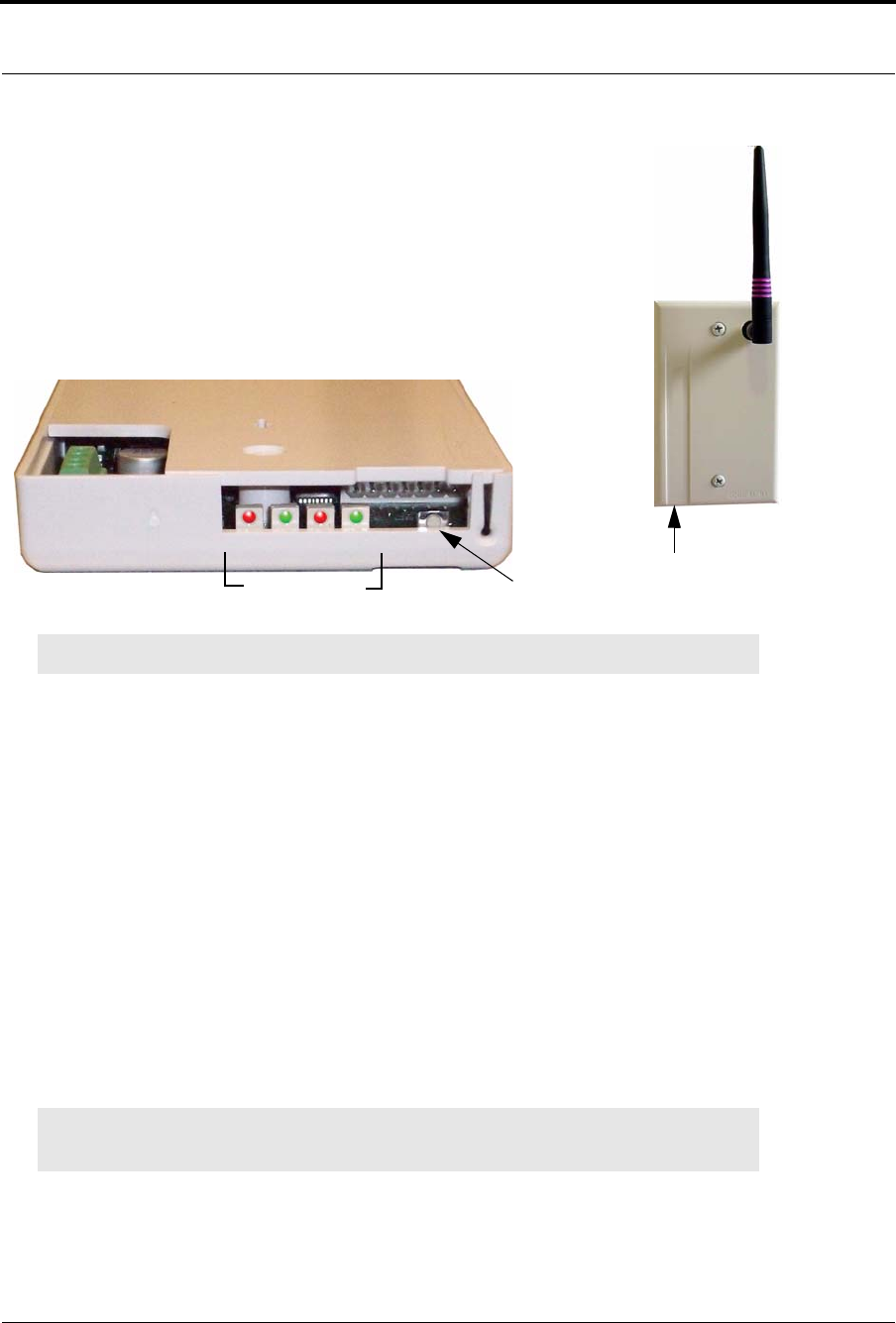
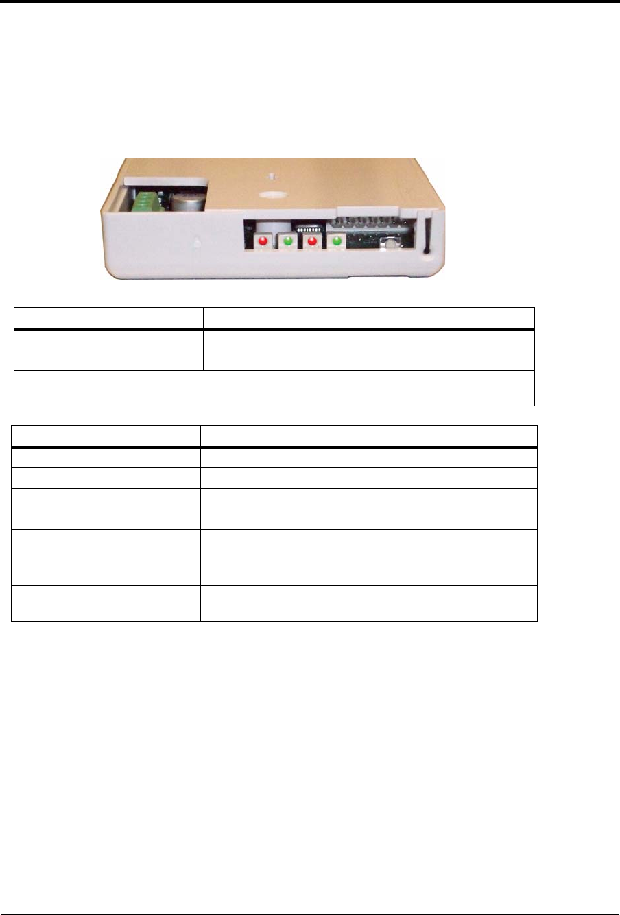
The Gateway has four (4) single-color LED lights; two green and two red. For more
information on LED lights and LED sequence refer to “LED Sequence” on page 13.
The two set of lights furthest from the Reset Button indicate transceiver device communication status. These
set of lights flashes briefly (once) every check-in (15 seconds by default) and when data is received or
transmitted.
•Green indicates communication is good (received data is formatted properly or the transmitted data was
sent successfully).
•Red indicates communication failure (received data has an error or the transmitted data was NOT sent
successfully).
The two set of lights closest to the Reset Button indicate RS232 communication status with the Central
Server. These set of flights flashes briefly (once) when data is transmitted via an external RS232 device to the
Central Server.
•Green indicates communication is good (transmission data acknowledged by the Central Server).
•Red indicates communication failure (transmission data NOT acknowledged by the Central Server). A
repeating, dim red LED flash (flashes once per second) indicates the device operating normally. Refer to “LED
Sequence” on page 13.
NOTE: The RF lights do not flash on the Router or Gateway in response to end device activity.
NOTE: The Gateway must be mounted at the maximum height from the ground and situated
where reception to affiliated Routers is not impaired.
Reset Button
Communication
Serial
Fail–Good
RF
Fail–Good
Reset Button

Chapter 1: Installing Hardware Components
6 9600 Series Wireless Call System (0510-1078-D) - Hardware Installation Guide
To install the Gateway directly to Server computer
1. Locate a mounting site for the Gateway that is within a 12-foot reach of the Central Server. To minimize noise
interference, the Gateway should be a minimum of 10-feet away from any wireless device or any high powered
electrical device.
Placement of the Gateway should not be located over a stud. The Gateway should be at a one-foot distance from
the bottom of the enclosure to the ceiling.
2. Using the rear plate of the Gateway as a template, place it level against the wall and mark the location of the two
mounting holes.
3. Center punch each hole and insert two nylon wall anchors (included).
4. Make certain that the RS232/Power Cable is plugged into the Gateway and that the ON/Off switch is in the ON
position.
5. Place the rear plate of the Gateway into the recess on the back of the Gateway enclosure.
6. With the antenna pointing upwards, place the Gateway over the wall anchors in alignment with the holes in the
enclosure and insert two screws (included).
7. If preferred, mount the raceway for containing and concealing the wires leading from the underside of the
Gateway down to the Central Server.
8. Connect the 9-Pin serial connector from the Gateway to the serial port on the Central Server.
9. Plug the power supply into a standard outlet. Using an uninterruptable power supply (UPS) is recommended.
10. If the power supply has a mounting tab, secure it to the outlet.
11. Using the software loaded on the Central Server, select the COM port assigned to the Gateway. Refer to the
section "Poll Server Settings" in the Series 6.0 Software Administrative Guide (PN 0510-1080).
To install the Gateway in or near a wiring closet
1. Locate a mounting site for the Gateway within the wiring closet. Placement of the Gateway should not be located
over a stud. The Gateway should be at a one-foot distance from the bottom of the enclosure to the ceiling.
2. Using the rear plate of the Gateway as a template, place it level against the wall and mark the location of the two
mounting holes.
3. Center punch each hole and insert two nylon wall anchors (included).
4. Make certain that the RS232/Power Cable is plugged into the Gateway and that the ON/OFF switch is in the ON
position.
5. Depending on which serial port server you use, do one of the following:
a. When using a 4-port serial port server (PN 9450-0910) with cable (PN 0460-0101), connect the RJ45 connector
from the Gateway to the top side of the serial port server. The serial port server is located within the black box
mounting assembly.
NOTE: In some circumstances where RF performance is impaired by a shielded wiring
closets or the location of the covered area is at a significant distance from the wiring
closet, the Gateway can be located outside the wiring closet by making use of the
provided 50 foot RS232/Power Cable.
9600 Series Wireless Call System (0510-1078-D) - Hardware Installation Guide 7
Installing Components
b. When using a single serial port server (PN 9600-0002) with cable (PN 0460-0124), connect the 9-
Pin connector from the Gateway to the single serial port server. Run Cat-5 wiring and terminate
each end with a RJ45 connector. Connect one end to the Ethernet connector on the bottom of the
single serial port server and the other end to the Ethernet switch.
Then, either plug the serial port into the CPS observing the polarity of the cable, red to (+ ) and
black to ( - ) or plug the power supply into a standard outlet. Using an uninterruptable power supply
(UPS) is recommended for standard output power.
6. Ensure that the wires are pulled through the wire tie wrap, secure them tightly with the wire tie and
cut off excess.
7. Place the rear plate of the Gateway into the recess on the back of the Gateway enclosure.
8. With the antenna pointing upwards, place the Gateway over the wall anchors in alignment with the
holes in the enclosure and insert two screws (included). Verify Gateway is firmly secured to the
wall to prevent device from falling.
9. Using the software loaded on the Central Server select the COM port assigned to the Gateway.
Refer to the section "Poll Server Settings" in the Series 6.0 Software Administrative Guide (PN
0510-1080).
To test the Gateway
1. Activate a transceiver and initiate an alarm event.
2. If the Gateway does not appear in the device list, verify that the appropriate communications port is
selected.
Install Routers
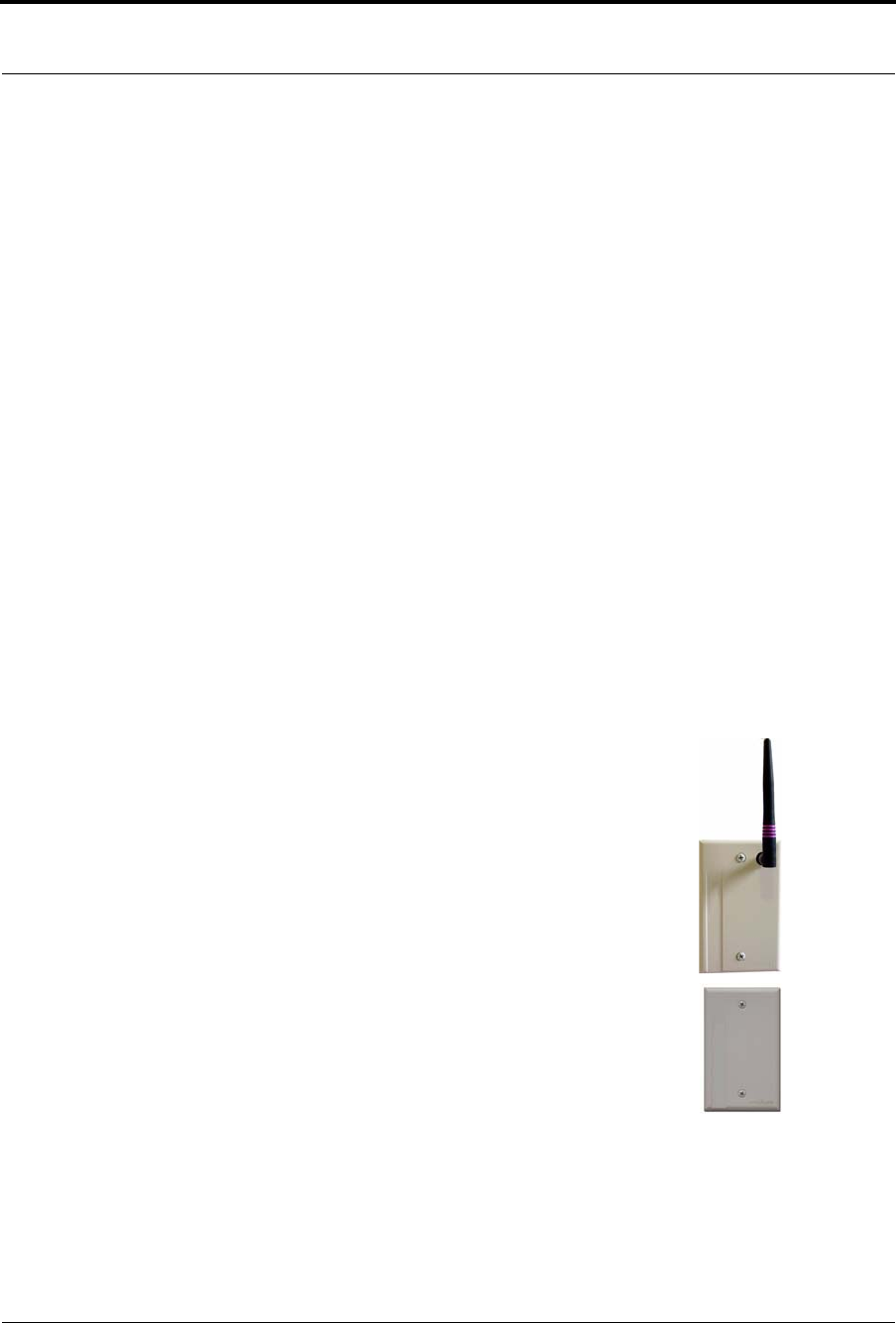
Routers receive signals from transceivers and re-transmit them to the Gateway. There are two
models of Routers, one with an internal antenna and one with an external antenna for greater
range. Routers can be supervised; a routine signal is sent from each Router and if the signal is
not received by the system, a Device Fault event is generated in the Event List at the computer.
The Router has four (4) single-color LED lights; two green and two red. For more information
on LED lights and LED sequence refer to “LED Sequence” on page 13.
The two lights furthest from the Reset Button indicate device transceiver communication
status These set of lights flashes briefly (once) every check-in (30 seconds by default), when a
tamper alarm is triggered or cleared, and when a data is forwarded.
•Green indicates communication is good and data is forwarded OK to the next Router.
•Red indicates communication failure and data is NOT forwarded to the next Router.
The two lights closest to the Reset Button indicate RS232 communication status. These set of lights flashes
briefly (once) when data is transmitted to an external RS232 device (i.e. Quick Look).
•Green indicates that the external RS232 device loopback is detected.
•Red indicates that the external RS232 device loopback is not detected.

Chapter 1: Installing Hardware Components
8 9600 Series Wireless Call System (0510-1078-D) - Hardware Installation Guide
Place a Pendant into Survey Mode
A Pendant in Survey Mode is used to survey the coverage area when installing Routers. Any Pendant
transceiver can be configured for Survey Mode. While in Survey Mode the Pendant periodically blinks either
green or red, depending on whether or not it is in range of a Router. Pressing the button on a Pendant in
Survey Mode does not generate or clear alarms.
Prepare Pendant for Survey Mode configuration
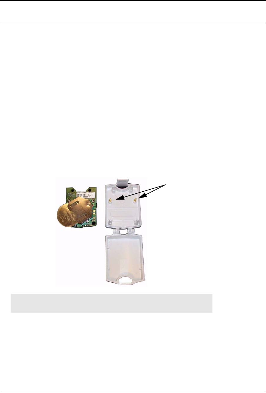
1. Insert the 3V Lithium coin cell battery into the Pendant.
2. Allow the Pendant to sit “untouched” for two minutes while it downloads the site’s channels.
3. Remove the battery from the Pendant.
To configure a Pendant for Survey Mode
1. Hold down the button on the Pendant transceiver.
2. While holding the button down, insert a 3V Lithium coin cell battery into the battery holder of the
Pendant transceiver.
3. Continue holding the button down until you see the light blink (approximately 2 seconds).
The Pendant blinks green or red every 1 1/2 seconds. Green indicates that the Pendant is within
range of a Router; red indicates the Pendant is outside of the coverage area.
To take a Pendant out of Survey Mode
1. Remove the 3V Lithium coin cell battery from the Pendant
2. Insert a “new” battery into battery holder of the Pendant. Do NOT hold the button down.
The Pendant is now ready for normal use (refer to “Pendant Transceivers” on page 40).

9600 Series Wireless Call System (0510-1078-D) - Hardware Installation Guide 9
Installing Components
Determine Placement of Routers
Routers are powered by a plug-in power supply or central power supply. A backup battery is also included in
the Router enclosure. Factors that affect the placement of Routers are the availability of a power source and
sufficient coverage for the supervision of transceivers.
1. The first Router's location is in the proximity of the Gateway as specified on the floor plan. Using a
Pendant that is in Survey Mode, walk a distance from the Gateway until the light on the Pendant
starts blinking red. This indicates that the Router is out of range of the Gateway.
2. Walk back into range.
3. Mount Router within range of the Gateway and near a 110 VAC wall outlet or at the termination
point from the central power supply. Repeat steps 1 and 2 to mount subsequent Routers.
NOTE: If using a 9V power supply, wiring from the power supply can be routed inside the wall or
(if preferred) mount the raceway for containing and concealing the wires leading from the
underside of the Router down to the 110 VAC wall outlet.
4. Placement of the Router should not be located over a stud and should be at a distance of one foot
from the bottom of the enclosure to the ceiling. The orientation of the Router should be vertical.
5. Using the rear plate of the Router as a template, place it level against the wall and mark the location
of the two mounting holes.
If the wiring from the wall outlet power supply or central power supply exits from being concealed
in the wall then locate the lower right corner of the rear plate (corner is cut out) over the exit hole.
6. Center punch each hole and drill in two nylon wall anchors (included). If the Router is located on a
concrete wall then you must use the wall anchors designed for use with concrete (not included).
7. Once the wiring has been run to the location of the Router attach the power supply wires to the
terminal block in the corner of the Router. If using a central power supply up to seven (7) Routers
may be daisy chained by terminating the next Router to the second terminal block. The minimum
field wire size to be employed shall be 22 AWG (0.36 mm2).
8. Ensure that the wires are pulled through the wire tie wrap, secure them tightly with the wire tie and
cut off excess.
9. Make certain that the Router’s ON/Off switch is in the ON position.
10. Place the rear plate of the Router into the recess on the back of the Router enclosure.
11. Place the Router over the wall anchors in alignment with the holes in the enclosure and insert two
screws (included). Verify Router is firmly secured to the wall to prevent device from falling.
12. If raceway is being used now is the time to apply it.
13. If the power is supplied by a wall outlet power supply then plug in the power supply.
14. If the power supply has a mounting tab, secure it to the outlet using the screw provided.
15. Repeat the above steps for the remaining Routers.
NOTE: A configuration map or floor plan of the facility is pre-determined with most 9600
Wireless Call Systems. Please rely on the configuration map or floor plan in conjunction
with the information provided below to determine Router placement.
Chapter 1: Installing Hardware Components
10 9600 Series Wireless Call System (0510-1078-D) - Hardware Installation Guide
Router Configuration in Multi-story Buildings
When a configuring a multi-story facility the Routers should be placed directly above one another as much as
possible to provide accurate location even in non-location required facilities.
Quick Look Router
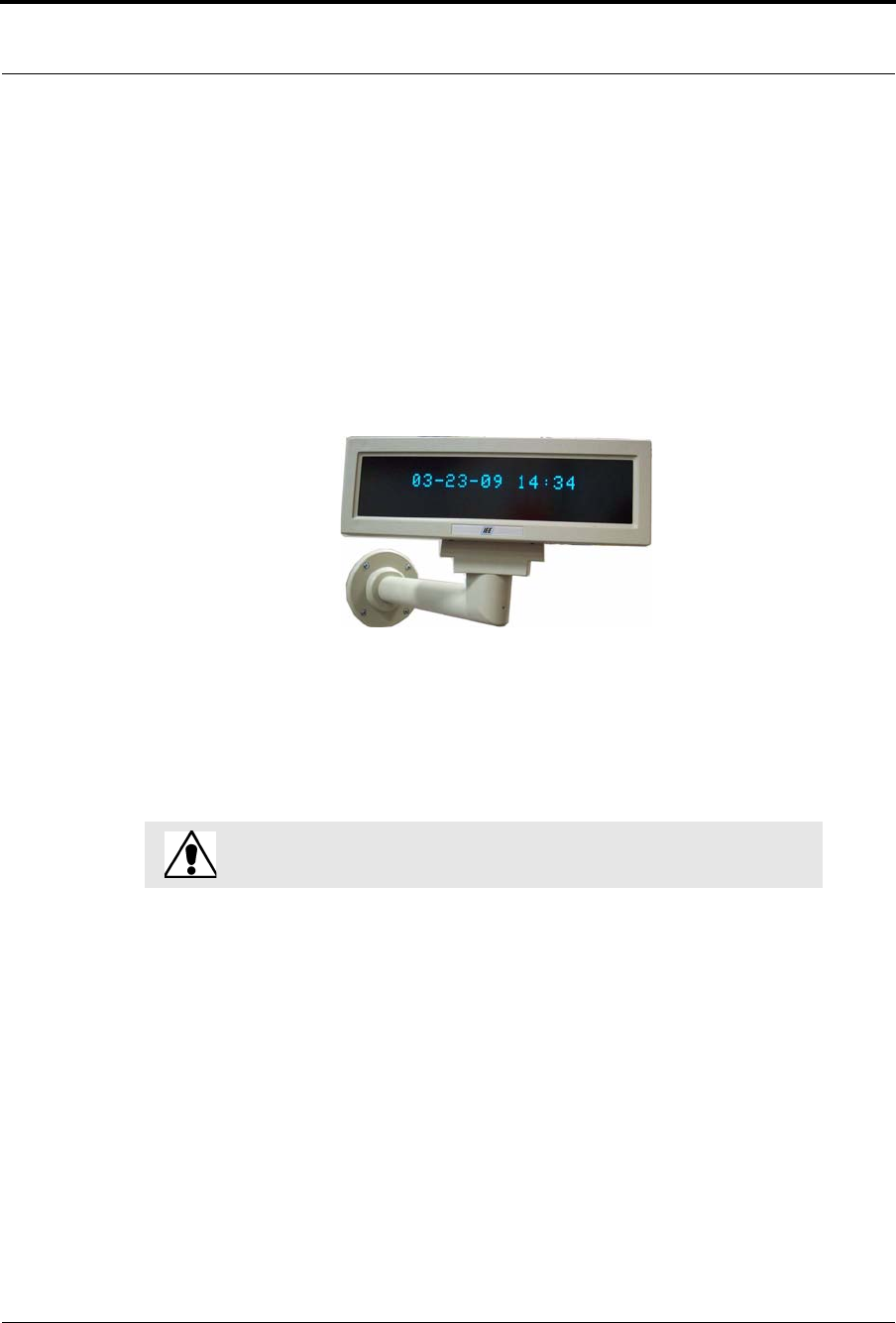
A Quick Look Router is an 9600 Series Router connected to a wireless Quick Look Display. When an alarm
is sent from the Server to the Router, the wireless display shows the type of alarm, location data and alarm
information. As new alarms occur, they appear immediately; the display then begins scrolling through each
active alarm.
The Quick Look Router also acts as an integral part of the back-up reflector. This reflector functionally
allows the 9600 Series network to take over the responsibility of distributing alarm information to the Quick
Look Routers in the event of an inoperable Server.
Quick Look Routers can be supervised; a routine signal is sent from each Quick Look Router and if the signal
is not received by the system, a Device Fault event is generated in the Event List at the computer.
WARNING: Quick Look Routers should not be added to multiple units. Since
Routers are used to determine location, inaccurate location data could result.
9600 Series Wireless Call System (0510-1078-D) - Hardware Installation Guide 11
Installing Components
To install the Quick Look Router with Quick Look Display
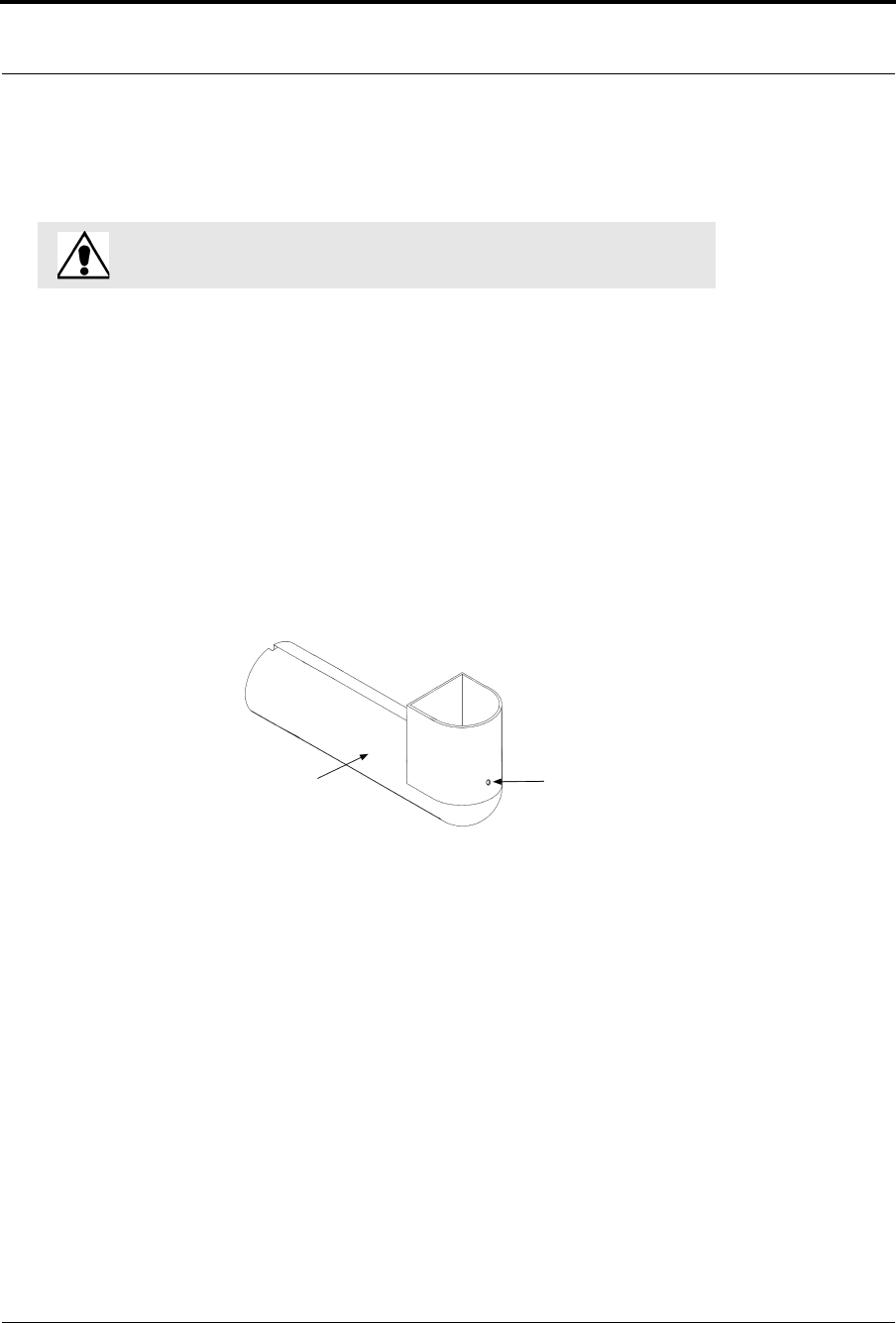
Use the following steps to mount the Quick Look Display.
1. Feed the wire attached to the head assembly of the Quick Look Display through the un-notched end
of the 4” wall-mount bracket.
2. Slide the head assembly onto the end of the 4” wall-mount bracket.
3. Secure it in place by tightening the set screw located on the end of the post or bracket.
4. Align the notches in the Quick Look base with the notches in the 4” wall-mount bracket and hold
together.
5. Feed the retaining nut over the wires leading out of the bottom of the base.
6. Tighten the retaining nut.
7. Be careful not to strip or damage the mounting base assembly.
8. Screw the base into the wall using the four screws provided.
9. Connect the Router to the Quick Look Display.
•Plug the RS-232 end of the 4-foot connector cable into the RS-232 terminal on the
lower right hand corner of the Router.
10. Wire the Router for power via the power terminal in the Router, noting the correct polarity.
11. Mount the Router within 4-feet of the Quick Look Display, near a 110 VAC wall outlet.
12. Power up the Router after powering up the display.
13. Connect the Router to 110 VAC wall power.
To test the Routers
1. For each Router use a Pendant that is in Survey Mode to test reception. Walk to the far reaches of
adjacent rooms and covered area to ensure that acceptable coverage is achieved.
2. For Quick Look Routers, verify location data and alarm information appears on the display when
an alarm is generated.
3. For more information contact or for technical support, contact the Technical Support Team at (800)
669-9946 or (262) 790-1771.
WA RNI N G: When installing a product, you must follow standard,
accepted safety practices, such as wearing safety glasses.
Set Screw
4” Wall Mount Bracket
Chapter 1: Installing Hardware Components
12 9600 Series Wireless Call System (0510-1078-D) - Hardware Installation Guide
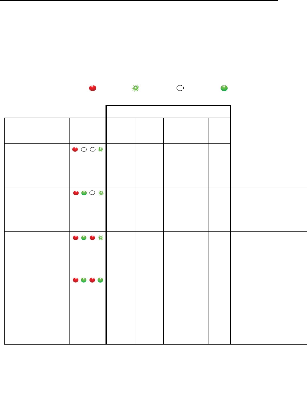
Gateway/Router Reset Button
The Router has four types of reset. Respectively, the Gateway supports the first three. By using the reset
button on the bottom edge of the Router/Gateway you can perform the resets described in the chart below.
Solid Red Flashing Green Non-illuminated Solid Green
Action Upon Release of Reset Button
Reset
Type To Execute Press
and Hold Reset
Button
Release Reset
Button When
LED Illuminates
Associated
(child)
End-
devices
Associated
(child)
Routers
Routing
Table Device
Name Channel
LED Sequence After Release of Reset
Button
1-second Hold until 1 LED
comes on solid
(about 1 second)
No change No change Clear No
change
Same 1.
2.
3.
4.
L1, L2, L3, L4 (sequentially)
All LEDs on
Green LEDs flash
Single green flash if
communication is successful
5-second Hold until 2 LED
comes on solid
(about 5 seconds)
Clear No change1Clear No
change
Same 1.
2.
3.
4.
L1, L2, L3, L4 (sequentially)
All LEDs on
Green LEDs flash
Single green flash if
communication is successful
10-second Hold until 3 LED
comes on solid
(about 10 seconds)
Clear Clear Clear Default225 1.
2.
3.
4.
L1, L2, L3, L4 (sequentially)
All LEDs on
Green LEDs flash
Single green flash if
communication is successful
15-second Hold until 4 LED
comes on solid
(about 15 seconds)
Clear Clear Clear Default2Scan31.
2.
3.
4.
5.
6.
L1, L2, L3, L4 (sequentially)
All LEDs on
No LED activity for 30 seconds
while channels are scanned
Green LEDs flash
Blink red RF 30 seconds
Single green LED flash and red RF
LED flashes for 15 seconds
1 If a Router/Gateway does not have child Routers (at the end of a branch in the tree structure), a 5-second reset will cause the Router/
Gateway to leave the network, and then rejoin the network. On the Router, this is indicated by observing the L2 flash off and back on
after 5 seconds.
2 A 10-second or 15 second reset will cause a Router/Gateway name to revert to factory default; Rout-xxxx/Gatexxxx, where xxxx
are the last 4 characters of the Router/Gateway MAC ID.
3 The Router will scan all channels and will join the first channel that replied with the highest RSSI (and stay on that channel
indefinitely).
9600 Series Wireless Call System (0510-1078-D) - Hardware Installation Guide 13
Installing Components
LED Sequence
Below is an explanation of the LED sequence.
Gateway/Router Channel Default
The Gateway and Router default to channel 25. In a facility with a single Gateway, it is recommended to
leave the Gateway and Routers on channel 25. In a facility with multiple Gateways, it is recommended to
power-up only one Gateway system at a time during installation. Once the first Gateway/Router system is up
and running, switch that system to another channel, then commission the next Gateway system (refer to
“Additional Gateway/Router Installation” on page 14).
LED Power Up Sequence Explanation of LED
L1, L2, L3, L4 (sequentially) Device executing normal firmware.
All LEDs On (not maintained) Device executing normal firmware.
NOTE: If power up sequence does not occur and the green light is blinking every second, than the device is in
manufacturer’s mode.
LED Display Sequence Explanation of LED
Dual Green LED Flash (10 times) Device is attempting to identify a Router/Gateway parent.
Single Green LED Flash (L2) Successfully joined with and checked in with identified parent.
Single Red LED Flash (L1) No response from identified parent.
Repeating (dim) Red LED Flash (L3) Device operating normally, flashes once per second (heart beat sequence).
Dual Green LED Flash (one time) Router/Gateway Successfully forwarded packet from a child to the
Central Server or display.
Single Green LED Flash (L4) Gateway received the check in message sent by Server every 15 seconds.
L3 and L4 Solid Illumination Battery switch turned off or battery fully discharged and requiring the
9600 Series Router Battery Recharger procedure (PN 0510-0336).
L4
L3
L2
L1
Chapter 1: Installing Hardware Components
14 9600 Series Wireless Call System (0510-1078-D) - Hardware Installation Guide
Additional Gateway/Router Installation
In some instances, it may be necessary to install an additional Gateway to support additional Routers. By
default, the Gateway and Routers are automatically assigned to channel 25. Once the first installation of
Gateway/Routers are complete and configured into the system, you must change the channel to install the
second set.
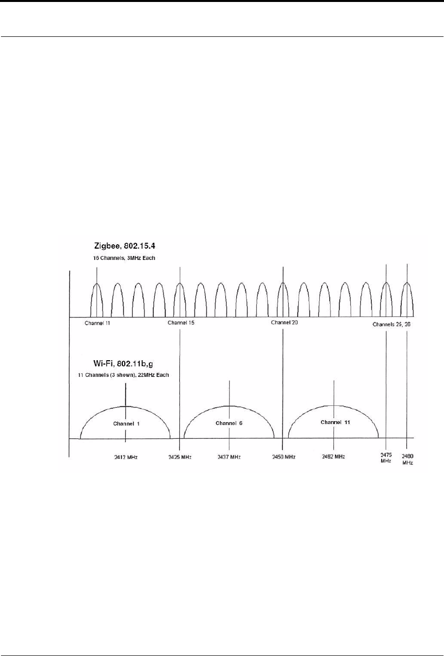
Channel selection will be site specific and dependant on the site’s environmental issues. Environmental
issues include WiFi, 2.4 GHz cordless phones, micowave ovens, and architecture (multiple Gateways). There
are 16 ZigBee channels in the 2.4 GHz spectrums numbered 11 to 26 (1–10 are in the 868–928 MHz
spectrum). Channel 26 is unusable as the power output is limited to half of the other channels due to its
proximity to the edge of the 2.4. GHz spectrums, and is configured “off” in the 9600 Wireless Call Systems.
Channel 25 is the default for all 9600 Series devices.
FIGURE 1.1: IEEE802.15.4 AND IEEE802.11 Channels
9600 Series Wireless Call System (0510-1078-D) - Hardware Installation Guide 15
Installing Components
Changing Channels
To change the channel to the Gateway and Routers you must access the Configuration-Device page.
1. From the Server computer running the Series 6.0 Software, select Tools from the Menu Bar.
2. Select Configuration from the drop-down menu.
3. If necessary, use your identification card or enter your Login and Password. Press Enter or click
OK. The System Management home page opens.
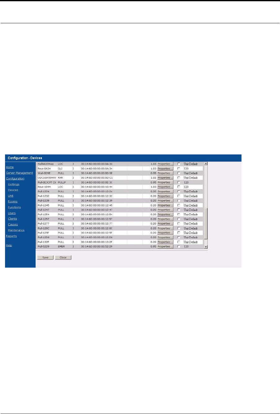
4. Select Configuration.The Configuration page opens with links to the Configuration menus.
All devices recognized by the system are listed in the Configuration Device window.
5. Select Devices.
The Configuration Devices window opens.
FIGURE 1.2: Configuration Device Window
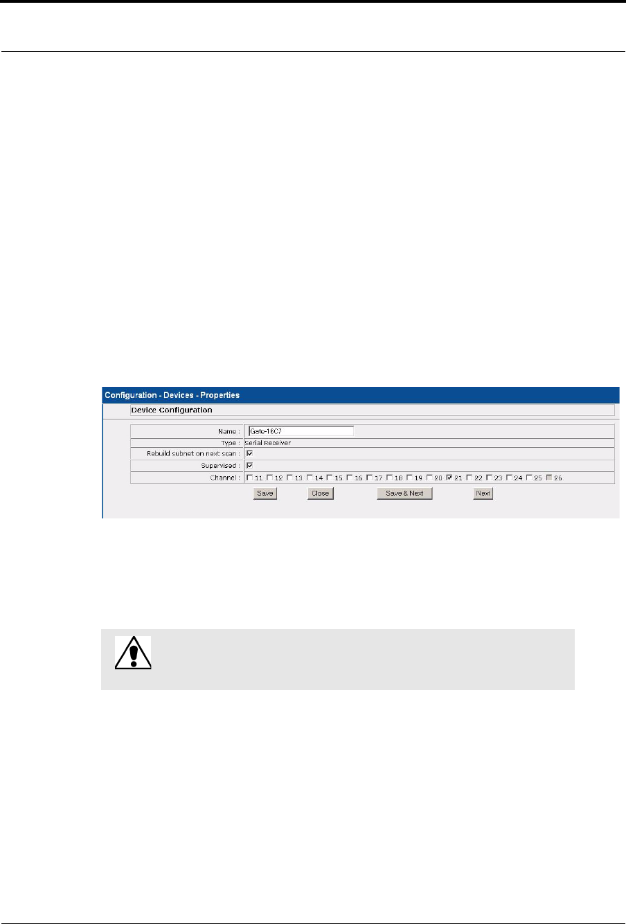
6. Click the Properties box next to the Gateway.
Chapter 1: Installing Hardware Components
16 9600 Series Wireless Call System (0510-1078-D) - Hardware Installation Guide
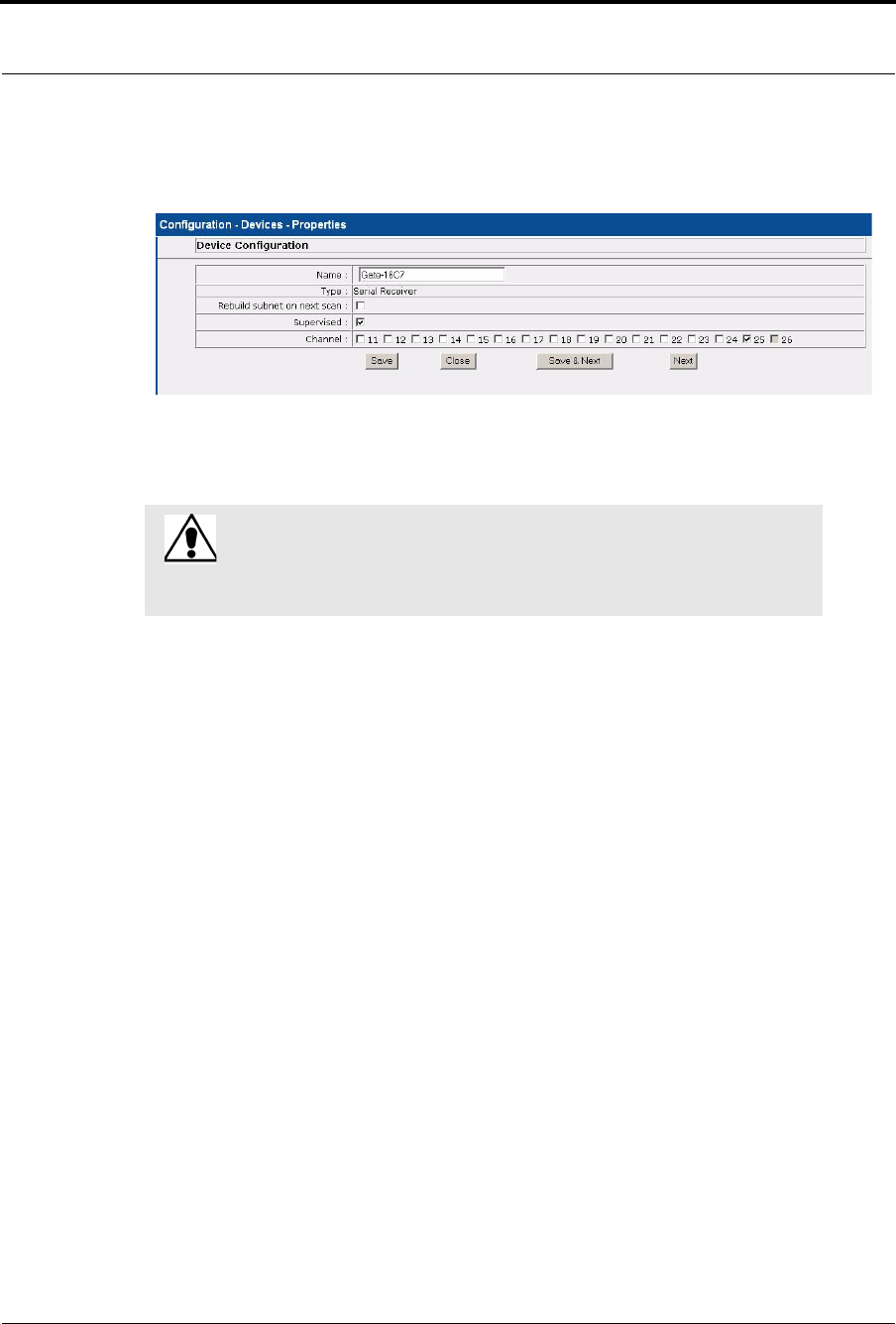
7. Deselect the default channel (25) and select the new channel. Selecting a new channel for the
Gateway will also change the channel for all associated Routers.
FIGURE 1.3: Device Properties Window
8. Click Save and then Close the window.
9. Once the channel for the Gateway and Routers has been changed, you must Scan Devices on that
comport to establish the change in the system. The Gateway will not use the new channel until the
Scan Devices function is complete.
WARNING: WAIT! You must wait at least 30 seconds and verify that all
Routers have checked in before using the Scan Devices function. As a rule you
should wait 100ms for each Router being changed before executing the Scan
Devices function.
9600 Series Wireless Call System (0510-1078-D) - Hardware Installation Guide 17
Installing Components
Router Depth
It is important to install Routers to minimize the number of hops to the Gateway while still providing
coverage at the furthest point from the Gateway. The Router Depth option allows you to adjust Router Depth
by staggering 5-second Router resets by one, two, three or four minutes. Each Router has an association limit
of 6 Routers; the hop limit for each Router is 4.
To select the Router Depth
1. From the Server computer running the Series 6.0 Software, select Tools from the Menu Bar.
2. Select Configuration from the drop-down menu.
3. If necessary, use your identification card or enter your Login and Password. Press Enter or click
OK. The System Management home page opens.
4. Select Configuration.The Configuration page opens with links to the Configuration menus.
All devices recognized by the system are listed in the Configuration Device window.
5. Select Devices.
The Configuration devices window opens.
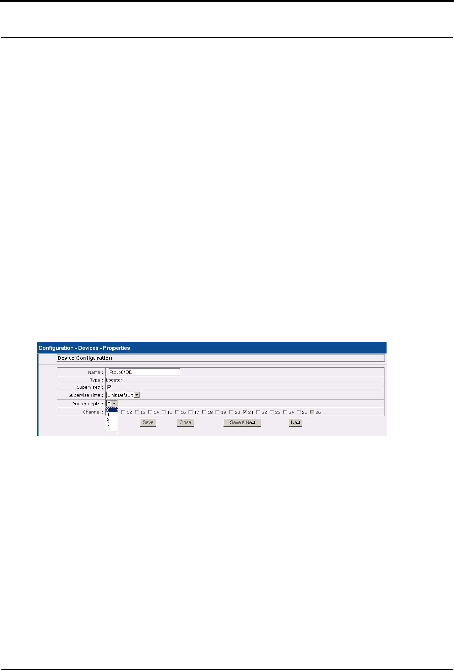
6. Click the Properties box next to the Router.
The Configuration Device Properties window opens.
FIGURE 1.4: Configuration Device Properties
7. Select the Router depth from the pull-down.
8. Click Save and the Close the window.
9. Once the Router Depth is selected, you must do a rebuild the subnet on scanned devices. (See
“Rebuild Subnet on Scanned Devices” on page 18.)
Chapter 1: Installing Hardware Components
18 9600 Series Wireless Call System (0510-1078-D) - Hardware Installation Guide
Rebuild Subnet on Scanned Devices
This option is used to rebuild the subnet on scanned devices.
1. From the Server computer running the Series 6.0 Software, select Tools from the Menu Bar.
2. Select Configuration from the drop-down menu.
3. If necessary, use your identification card or enter your Login and Password. Press Enter or click
OK. The System Management home page opens.
4. Select Configuration.The Configuration page opens with links to the Configuration menus.
All devices recognized by the system are listed in the Configuration Device window.
5. Select Devices.
The Configuration devices window opens.
6. Click the Properties box next to the Gateway.
The Configuration Device Properties window opens.
FIGURE 1.5: Configuration Device Properties
7. Click the checkbox next to Rebuild subnet on next scan.
8. Click Save and then Close the window.
9. You must execute the Scan command on that Gateway’s comport to begin.
WARNING: Rebuilding the subnet should only be done when end
devices are not present during installation. During the Rebuild, the
system will be down for up to 10 minutes.
9600 Series Wireless Call System (0510-1078-D) - Hardware Installation Guide 19
Installing Components
Scan Devices
The Server Management window allows you to Scan devices.
1. On the Menu Bar select Tools.
2. Select Configuration from the drop-down menu.
3. If necessary, use your identification card or enter your Login and Password. Press Enter or click
OK.
The System Management Home page opens.
4. Select Server Management.
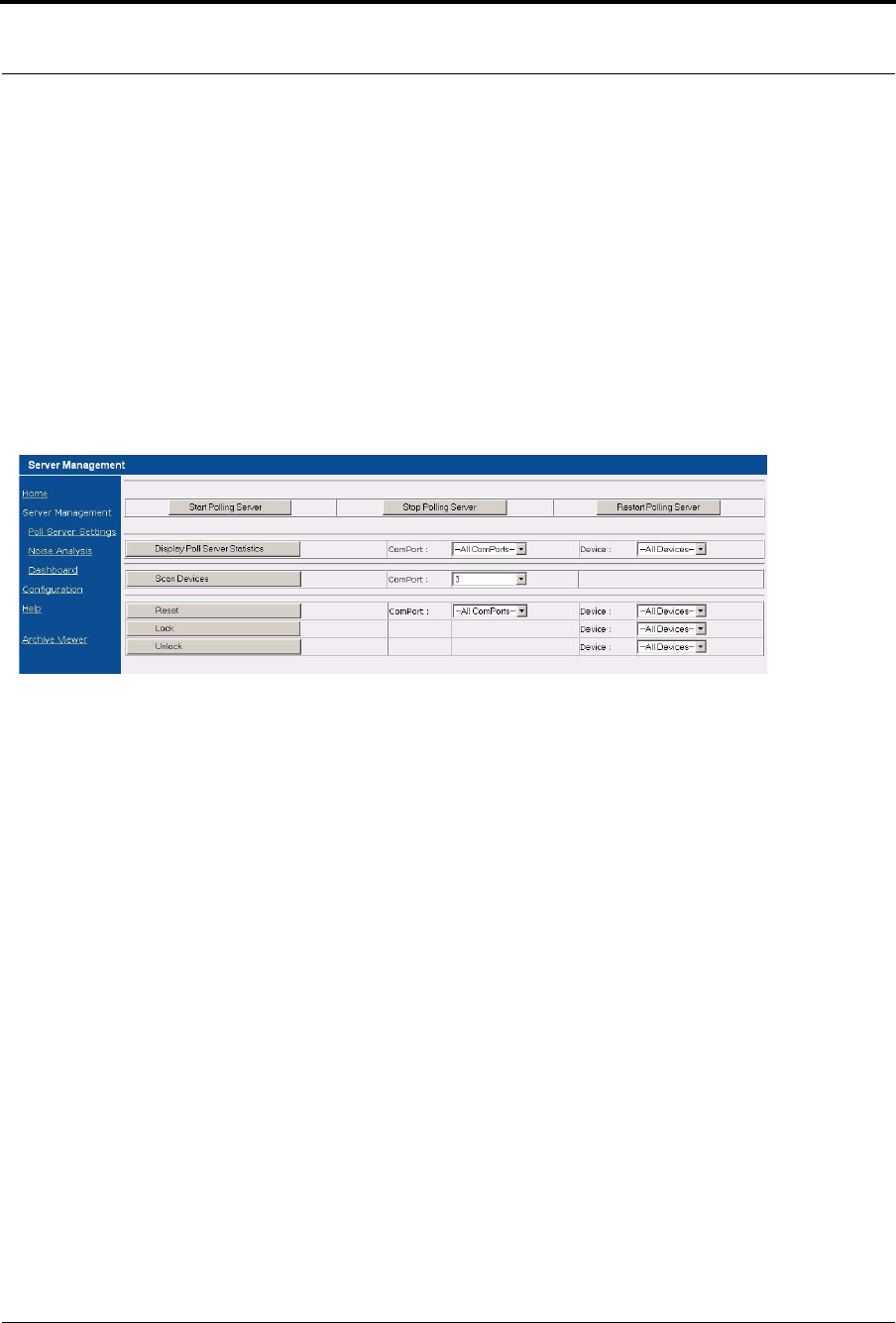
The Configuration Server Management home page opens.
FIGURE 1.6: Configuration Server Management Home Page
5. Next to the Scan Devices button, select the ComPort assigned to the Gateway/Router from the
ComPort pull-down.
6. Click Scan Devices, a Scan Status window opens verifying the successful completion of the scan.
7. Click Close to close the Scan Status window and return to the Server Management home page.
8. Open the Dashboard and verify the Gateway and each of the Routers are communicating.
9. Install the next Gateway and Routers.

Chapter 1: Installing Hardware Components
20 9600 Series Wireless Call System (0510-1078-D) - Hardware Installation Guide
This page intentionally left blank.
9600 Series Wireless Call System (0510-1078-D) - Hardware Installation Guide 21
Chapter 2
Installing Transceiver Devices
Introduction
This chapter provides detailed information about installing transceiver devices and testing the operations of
the 9600 Series Wireless Call System with those devices. Transceivers are devices that transmit and receive
data. The transceiver devices listed in this section are supported by the Code Alert 9600 Wireless Call System
running the Series 6.0 Software application. The Code Alert 9600 Wireless Call System includes transceivers
that are carried by the patient and fixed devices. A fixed device is a stationary device that is assigned to a
room or a unit. Fixed devices are not transported with the patient but stays in the unit to which they are
assigned.
Transceiver Devices
The transceiver devices are entered into the system by placing the device into an alarming state. The system
senses the device when the device goes into alarm and adds it to the device list in the Configuration-Device
window.
The user must then update the device information; for example, give the device a name and/or enable
features, refer to the Series 6.0 System Administrator Guide (PN 0510-1080).
The Code Alert 9600 Wireless Call System transceiver devices consist of the following:
•Pull Cord
•Wall Mount Emergency Call
•Universal
•Nurse Call
•Door/Window
•PIR Sensor
•Smoke Detector
•Pendant
WARNING: Before cutting openings or drilling holes through walls, you must
verify that you will not strike any wiring or plumbing.
NOTE: Pull Cords and Universal Transceivers check in every 20 minutes; Pendants
check-in every 100 seconds by default. These devices will auto populate the device list
when they check-in.

Chapter 2: Installing Transceiver Devices
22 9600 Series Wireless Call System (0510-1078-D) - Hardware Installation Guide
LED Light Indicator
The Pendant, Pull Cord and Universal transceivers contain a two-color indicator light. In general, green
indicates good and red indicates bad.
No light—if the LED indicator does not blink within a few seconds of alarming or clearing an alarm,
this may indicate a dead battery; try replacing the battery. If the problem persists, contact Technical
Support.
3 green blinks—alarm, clear, or check-in had been transmitted and a confirmation has been received
from the Gateway.
10 green blinks—device has successfully received new configuration data from the computer.
1 green blink—alarm, clear or check-in has been transmitted but the device has not yet received a
confirmation from the Gateway. Wait up to 15 seconds for the device to try again by itself; do not re-
alarm the device. The Pendant will also blink green once each time the blue button is pressed; as visual
feedback that the button press was recognized.
1 red blink—device cannot find a Router to communicate with; device may be out of range or on the
wrong channel.
2 red blinks—join failed; the device found one or more Routers, but Routers indicate they cannot
accept any additional devices. An additional Router may need to be added to support a large number of
devices in the same area.
Installing Transceiver Devices
Pull Cords/Emergency Call
A Pull Cord is usually mounted on the wall. This device is used to request staff assistance
and is commonly used in bedrooms and bathrooms. It is suitable for use in close
proximity to showers or baths; however to prevent damage, avoid any submersion.
The Pull Cord has one (1) LED light. The light is visible when the enclosure is open (i.e.
during installation), but not visible during normal operation when the enclosure is closed.
The light flashes briefly once every check-in (20 minutes by default), once each time the
device alarm is triggered or cleared, and once when the optional check-in button is
pressed. Green indicates that communication with the Router is good; red indicates
communication failure and the device is not able to transmit to the Router.
An Assistance Required alarm event is reported in the Event List when a patient pulls the
cord. The Pull Cord is supervised; a routine signal is sent from the transceiver and if the
signal is not received by the system, a Device Fault event is generated in the Event List at
the computer.

9600 Series Wireless Call System (0510-1078-D) - Hardware Installation Guide 23
Installing Transceiver Devices
Check-in Pull Cord
A Check-in Pull Cord enables the staff or patient to push a green button to check-in. Pressing the green button
indicates to the system that the patient has checked in or been visited by staff. The type of check-in depends
on how your Pull Cord is configured, refer to the Series 6.0 Software Administrator Guide (PN 0510-1080).
Check-in types
•Patient Check In—A patient pushes the button to notify the staff that he/she is awake and does not
require assistance.
•Staff Check In—A staff member pushes the check-in button once they have checked on a patient.
•Staff Care Complete—A staff member pushes the check-in button in response to an Assistance
Required alarm once the patient has been checked on and the alarming device is reset. If JCAHO is
enforced, this will clear the White alarm from the Client computer
To mount the Pull Cord transceiver
1. Using the rear plate of the Pull Cord as a template, place it level against the wall at the desired
mounting height and mark the location of the two mounting holes. A height of 48 inches is
standard.
2. Center punch each hole and install two nylon wall anchors (included). If the Pull Cord is located on
a concrete wall then you must use the wall anchors designed for use with concrete (not included).
Make certain that wall anchors are installed straight and flush to the face of the wall. If not this will
cause the alarm lever to bind and thus not release correctly.
3. Determine the desired length of the red Pull Cord string. The standard length of a Pull Cord strings
is six feet long. However, as mounting heights vary, the length of the string may need to be
adjusted.
To adjust the length of the Pull Cord string:
a. Gently pop the red alarm lever free from the enclosure and remove the string.
b. Cut the string to the desired length and rewind it on the alarm lever in the reverse order it was
removed. There are instructions printed on the side of the red alarm lever for assistance in
winding the string.
c. Press the red alarm lever back onto the enclosure and route the pull cord string through the
small slit in the bottom corner of the enclosure.
4. Pull the plastic battery tab to activate the battery or refer to the section entitled “To replace the
battery to the Emergency Call” on page 28 to insert a new battery.
5. Place the rear plate of the Pull Cord into the recess on the back of the transceiver enclosure.
6. Place the Pull Cord assembly over the wall anchors in alignment with the holes in the enclosure and
insert two screws (included).
NOTE: Do not over tighten the screws as this will cause the alarm lever to bind and thus
not release correctly.

Chapter 2: Installing Transceiver Devices
24 9600 Series Wireless Call System (0510-1078-D) - Hardware Installation Guide
Pull Cord Transceiver with Extended Battery Pack
The Pull Cord Transceiver can be either surface mounted or flush mounted. Due to the size of the Extended
Life Battery Pack a surface mount enclosure or single gang enclosure will be required to house the battery
holder. The following sections provide detailed steps on how to mount the transmitter using both methods.
To surface mount the Transceiver
1. Hold the base of the surface mount enclosure against the wall at the desired mounting height.
2. Mark the location of the two mounting holes.
3. Drill holes where the marks were made. If the drilled holes do not hit a stud wall, you must use wall
anchors.
4. Line up the holes on the base of the enclosure with the newly drilled holes.
5. Mount the base of the enclosure to the wall using two drywall screws.
6. Determine the desired length of the pull cord string. The standard length of a Pull Cord strings is six
feet long. However, as mounting heights vary, the length of the string may need to be adjusted.
7. Connect the battery pack to the pigtail connector on the Pull Cord assembly.
8. Make certain that the pigtail wires leading from the Pull Cord Assembly pass through the cutout in
the back enclosure cover and that they are not pinched.
9. Place the pull cord assembly aligned over the mating holes in the surface mount enclosure and
secure in place with the two screws provided.
NOTE: Do not over tighten the screws as this will cause the alarm lever to bind and thus
not release correctly.

9600 Series Wireless Call System (0510-1078-D) - Hardware Installation Guide 25
Installing Transceiver Devices
To flush mount the Transceiver
1. Hold the base of the flush mount enclosure against the wall at the desired mounting height and trace
the outline of the flush mount enclosure.
2. Cutout the hole along the traced lines.
3. Insert the flush mount enclosure into the hole and secure in place by routing the wall mounting
flaps outward and tight against the inside surface of the drywall.
4. Determine the desired length of the pull cord string. The standard length of a Pull Cord strings is six
feet long. However, as mounting heights vary, the length of the string may need to be adjusted.
5. In order for the battery pack to fit into the single gang box the two halves that hold the batteries
need to be folded in half. To do this remove the liner from the tape strip on the back side of the
Extended Life Battery Pack and slowly fold the two halves together in order to adhere one half to
the other.
6. Connect the battery pack to the pigtail connector on the Pull Cord assembly.
7. Make certain that the pigtail wires leading from the Pull Cord Assembly pass through the cutout in
the back enclosure cover and that they are not pinched.
8. Place the pull cord assembly aligned over the mating holes in the flush mount enclosure and secure
in place with the two screws provided.
To set up the Pull Cord for use
1. Activate the Pull Cord by pulling the cord.
If the transceiver is working properly, the Central Server will sense the transceiver when it goes into
alarm and add it to its list of devices.
2. Reset the Pull Cord by rotating the red HELP lever back to the UP position.
3. At the Central Server, update the Pull Cord information, for example, giving the Pull Cord a name
and/or assigning it to a room or unit. Refer to the “Update Devices” section in the Series 6.0
Software Administrator Guide (PN 0510-1080).
NOTE: Do not over tighten the screws as this will cause the alarm lever to bind and thus
not release correctly.
Chapter 2: Installing Transceiver Devices
26 9600 Series Wireless Call System (0510-1078-D) - Hardware Installation Guide
To replace the battery to the Pull Cord
1. Use a small Phillips screwdriver to remove the front cover
of the Pull Cord from its wall mounting.
2. Grip the battery holder and use a small flat screwdriver to
hold back the top circuit board retainer clip.
3. Gently pry up that corner of the circuit board past the
retaining clip. Repeat for the second retaining clip and
remove the circuit board.
4. If changing the battery, use a small, non-conductive piece
of plastic or wood to push the 3V Lithium coin cell battery
from the rear of the battery clip until it comes free.
5. Insert the new 3V Lithium coin cell battery into the battery holder. Be sure to align the positive (+)
end of the battery as marked on the battery and battery holder.
6. Verify communication by observing the LED light.
7. Once communication is verified, return the circuit board into the enclosure, slide the left edge of the
circuit board under the two lower retaining clips then lower the top end down and gently push until
it snaps under the two upper retaining clips.
8. Replace the front cover of the Pull Cord to its wall mounting.
To replace the AA Batteries for the Pull Cord with Extended Life Battery Pack
1. Remove the Pull Cord Assembly from its enclosure.
2. Grip the battery holder and pull all four batteries free from the battery holder.
3. Insert four new AA Lithium Ion batteries into the battery holder.
4. Verify communication by observing the LED on the Pull Cord circuit board.
5. Once communication is verified replace the rear cover of the Pull Cord and remount it to the surface or
flush mount enclosure.
NOTE: Do not use a metal screwdriver or metallic instrument to remove the battery. This
may damage the device.
NOTE: Do not use a metal screwdriver or metallic instrument to remove the battery. This
may damage the device.
Retaining Clips
9600 Series Wireless Call System (0510-1078-D) - Hardware Installation Guide 27
Installing Transceiver Devices
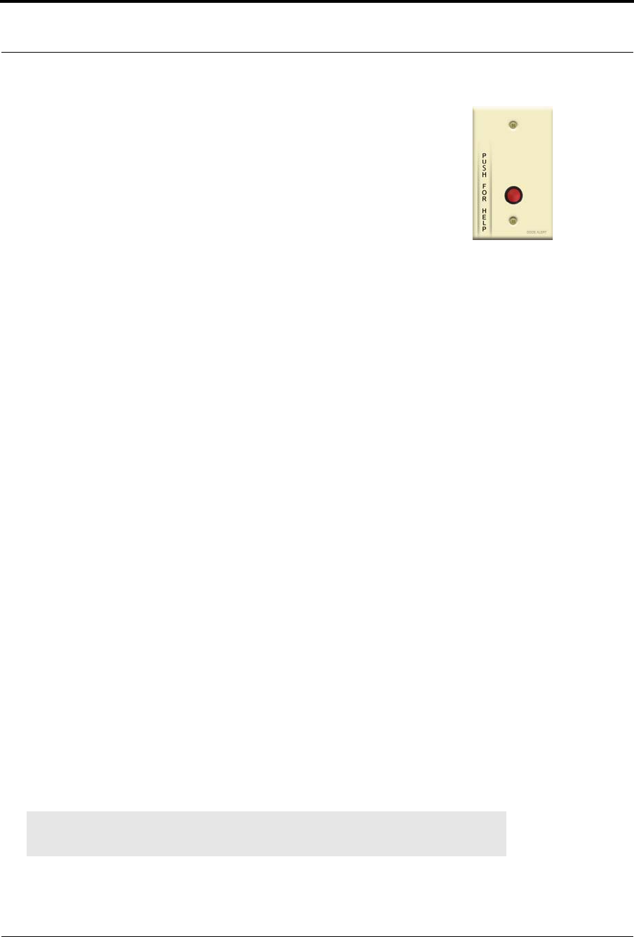
Wall Mount Emergency Call
A Wall Mount Emergency Call is mounted on the wall. This device is used to request staff
assistance and is commonly used in bedrooms and bathrooms. It is suitable for use in close
proximity to showers or baths; however to prevent damage, avoid any submersion.
The Wall Mount Emergency Call has one (1) LED light. The light is visible when the
enclosure is open (i.e. during installation), but not visible during normal operation when
the enclosure is closed. The light flashes briefly once every check-in (20 minutes by
default) and once each time the device alarm is triggered or cleared. Green indicates that
communication with the Router is good; red indicates communication failure and the
device is not able to transmit to the Router.
An Assistance Required alarm event is reported in the Event List when a patient pushes the red button. The
Emergency Call is supervised; a routine signal is sent from the Emergency Call and if the signal is not
received by the system, a Device Fault event is generated in the Event List at the computer. The Wall Mount
Emergency Call is powered by a replaceable 3V battery.
To mount the Emergency Call transceiver
1. Using the rear plate of the Emergency Call as a template, place it level against the wall at the
desired mounting height and mark the location of the two mounting holes. A height of 48 inches is
standard.
2. Center punch each hole and install two nylon wall anchors (included). If the Emergency Call is
located on a concrete wall then you must use the wall anchors designed for use with concrete (not
included).
3. Pull the plastic battery tab to activate the battery or refer to the section entitled “To replace the
battery to the Emergency Call” on page 28 to insert a new battery.
4. Place the rear plate of the Emergency Call into the recess on the back of the transceiver enclosure.
5. Place the Emergency Call assembly over the wall anchors in alignment with the holes in the
enclosure and insert two screws (included).
To set up the Emergency Call for use
1. Activate the Emergency Call by pushing the red button. When pushed, the button remains in
indicating the device is in an alarm state.
If the Emergency Call is working properly, the Central Server will sense the Emergency Call when
it goes into alarm and add it to its list of devices.
2. Reset the Emergency Call by pushing the red button again, the button pops out indicating the
transceiver has changes states and is now idle and ready for its next usage.
3. At the Central Server, update the Emergency Call information, for example, giving the Emergency
Call a name and/or assigning it to a room or unit. Refer to the “Update Devices” section in the
Series 6.0 Software Administrator Guide (PN 0510-1080).
NOTE: The Emergency Call will enroll as a Pull Cord. The device type must be updated
for it to function properly.
Chapter 2: Installing Transceiver Devices
28 9600 Series Wireless Call System (0510-1078-D) - Hardware Installation Guide
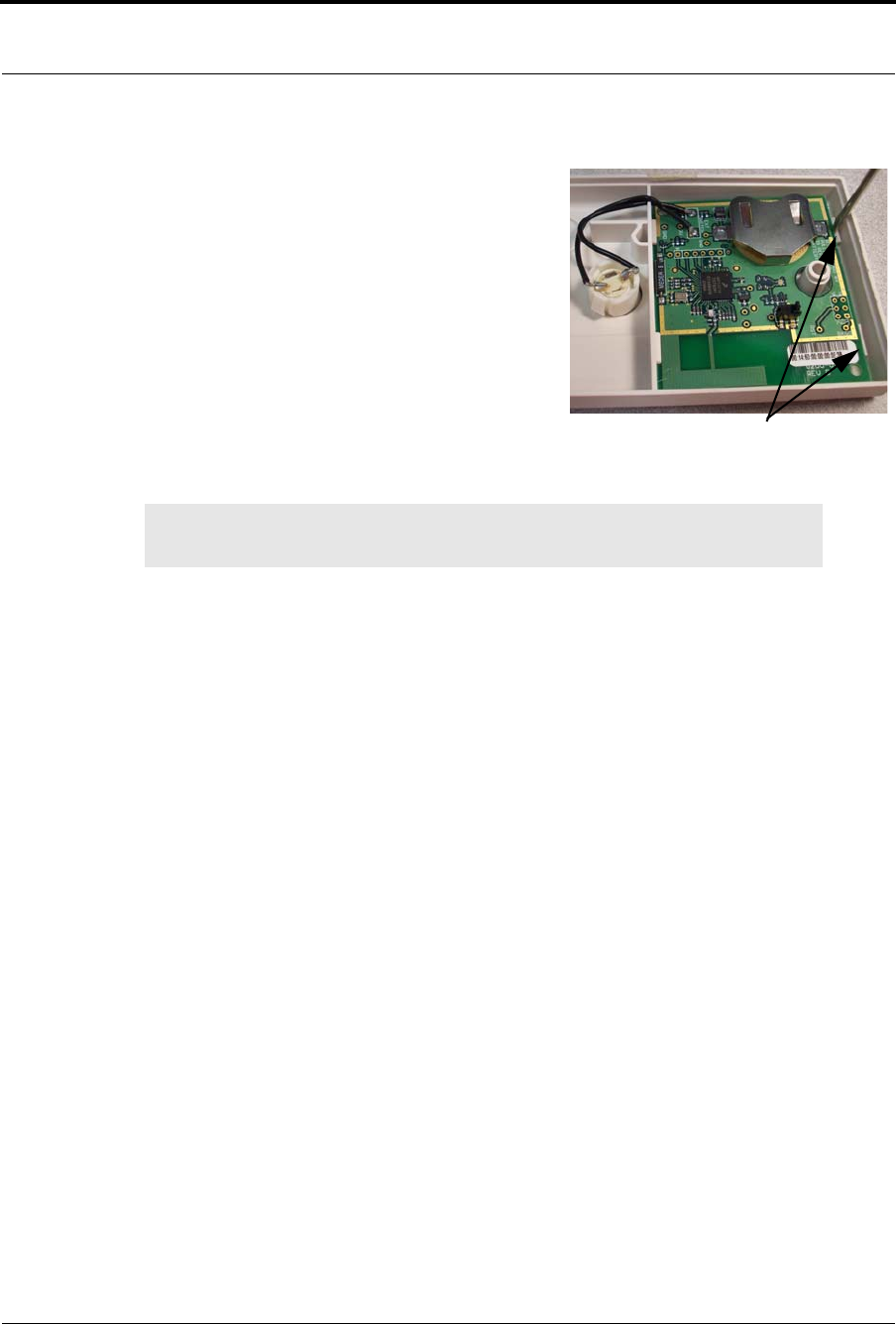
To replace the battery to the Emergency Call
1. Use a small Phillips screwdriver to remove the front
cover of the Emergency Call from its wall
mounting.
2. Grip the battery holder and use a small flat
screwdriver to hold back the top circuit board
retainer clip.
3. Gently pry up that corner of the circuit board past
the retaining clip. Repeat for the second retaining
clip and remove the circuit board.
4. If changing the battery, use a small, non-conductive
piece of plastic or wood to push the 3V Lithium coin
cell battery from the rear of the battery clip until it comes free.
5. Insert the new 3V Lithium coin cell battery into the battery holder. Be sure to align the positive (+)
end of the battery as marked on the battery and battery holder.
6. Verify communication by observing the LED light.
7. Once communication is verified, return the circuit board into the enclosure, slide the left edge of the
circuit board under the two lower retaining clips then lower the top end down and gently push until
it snaps under the two upper retaining clips.
8. Replace the front cover of the Emergency Call to its wall mounting.
NOTE: Do not use a metal screwdriver or metallic instrument to remove the battery. This
may damage the device.
Retaining Clips
9600 Series Wireless Call System (0510-1078-D) - Hardware Installation Guide 29
Installing Transceiver Devices
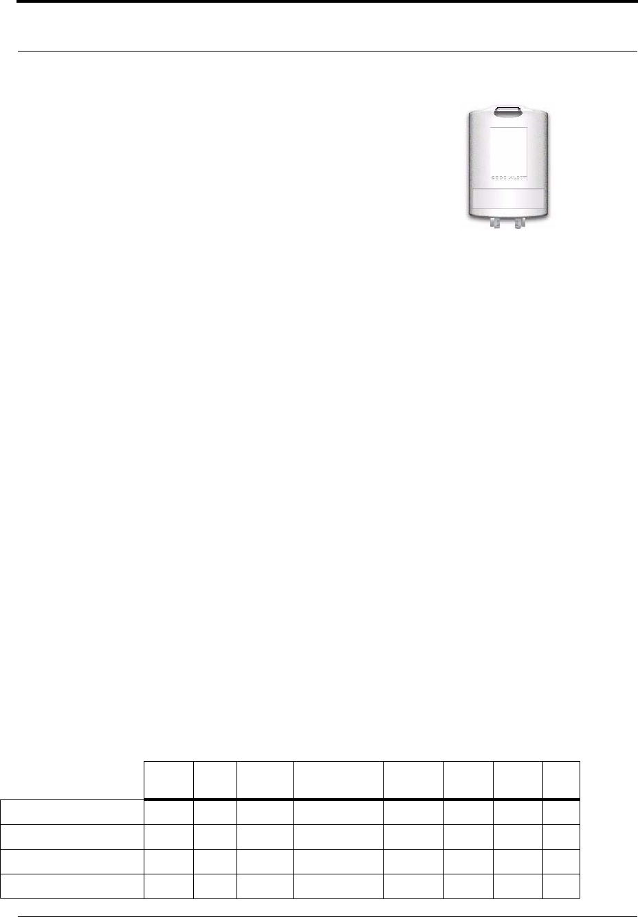
Universal Transceiver
A Universal transceiver can be used to integrate your facility’s existing equipment
such as backup generators or other devices that can be integrated with the software.
Universal transceivers can be programmed as either NO (normally open) or NC
(normally closed) devices. They automatically activate when the input from a
monitored device has a contact close. When this happens, the Universal transceiver
sends event information to the Central Server. The Universal transceiver is powered
by a replaceable 3V battery.
The Universal has one (1) LED light. The light is visible when enclosure door is open (i.e. during
installation), but not visible during normal operation when the enclosure door is closed. The light flashes
briefly once every check-in (20 minutes by default) and once each time the device alarm is triggered or
cleared. Green indicates communication with the Router is good; red indicates communication failure and
device is not able to transmit to the Router.
To wire the Universal transceiver connect the two 22-gauge, 2-conductor stranded wire into the appropriate
terminals on the existing device. Refer to the device manufacturer’s instructions or contact the RF
Technologies, Inc. Technical Support Team at (800)-669-9946 or (262) 790-1771 to identify the correct
terminals.
The Universal transceiver can be mounted with a screw using a mounting hole; it can be applied with the
attached adhesive pad; or it can be mounting with a lanyard or zip tie through the opening at the top of the
transceiver.
Tamper
The Universal transceiver’s tamper functionality operates in several modes depending on the device and the
type of tamper interference. In either case, when initiated, a Ta mp er alarm event will be listed on the Event
List at the Central Server. The types of tamper events are:
•Case Open Tamper— initiated when the case to the Universal transceiver is opened.
•Mounting Tape Tamper—initiated when the PCB is separated from the enclosure.
•Nurse Call Cord Set Tamper—initiated when the Nurse Call Cord set is removed from the Nurse
Call transceiver.
•Externals Enclosure Tamper —initiated when the external closure of the PIR Sensor is opened.
Below is a table showing the type of tamper event associated with a particular device.
Nurse
Call EAC Door/
Window Door Manual
Reset Door
Check-in PIR Smoke CO
Case Open Tamper xx x x x x
Mounting Tape Tamper xx x x x
Nurse Call Cord Set Tamper x
External Enclosure Tamper x
Chapter 2: Installing Transceiver Devices
30 9600 Series Wireless Call System (0510-1078-D) - Hardware Installation Guide
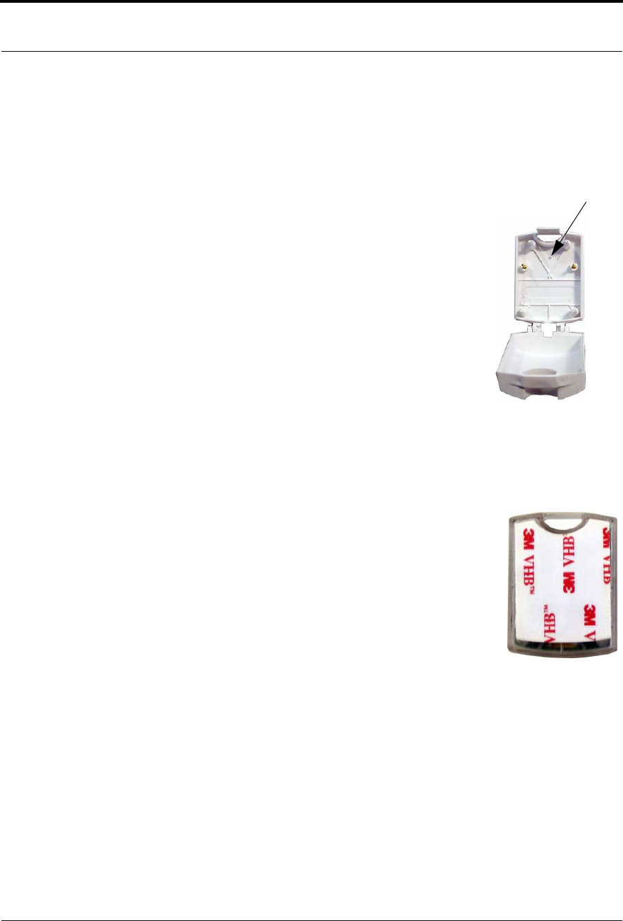
To mount the Universal transceiver using mounting hole
1. Use your fingers to open the front cover of the transceiver by pushing the retaining clip on the top
downward. This allows the hinged cover to drop down and expose the circuit board.
2. Carefully pull the circuit board free from the pins on the enclosure.
3. Drill a 1/8 inch mounting hole through the indentation in the transceiver
enclosure.
4. Using the enclosure of the Universal transceiver as a template, place it
level against the wall and mark the location of the mounting hole.
5. Mark out the mounting hole and drill a 1/16 inch diameter hole where
you made the mark.
6. Line up the hole on the transceiver enclosure with the newly drilled hole
and mount the enclosure to the door frame using a number 6 screw (not
included).
7. Pull the plastic battery tab to activate the battery or refer to the section
entitled “To replace the battery in a Universal transceiver” on page 31
to insert a new battery.
8. Return the circuit board onto the two pins.
9. Snap the front cover of the transceiver back into place.
To mount the Universal transceivers with adhesive pad
The Universal transceiver can be attached using an adhesive pad that can be
purchased with the transceiver.
1. Remove an adhesive pad from the strip of paper.
2. Place the transceiver face down.
3. Line the adhesive pad up with the back of the transceiver.
4. Apply the adhesive pad.
5. Verify that the pad is applied correctly and is not hanging over the sides
of the transceiver.
6. Determine where you want to apply the transceiver. The surface must be clean, dry and free of
condensed moisture.
7. Pull the plastic battery tab to activate the battery or refer to the section entitled “To replace the
battery in a Universal transceiver” on page 31 to insert a new battery.
8. Remove the adhesive plastic guard.
9. Firmly attach the transceiver to the mounting surface. Ideal application temperature range is 70°F to
100°F (21°C to 38°C).
10. Press firmly and hold for approximately 10 seconds to activate the pressure sensitive adhesive.
11. After application, the bond strength will increase as the adhesive flows onto the surface. At room
temperature, approximately 50% of ultimate bond strength will be achieved after 20 minutes, 90%
after 24 hours and 100% after 72 hours.
Drill hole
9600 Series Wireless Call System (0510-1078-D) - Hardware Installation Guide 31
Installing Transceiver Devices
To set up the Universal transceiver for use
1. Activate the Universal transceiver by inserting the battery.
2. Test the transceiver by activating the existing device.
If the transceiver is working properly, the Central Server will sense the Universal when it goes into
alarm and add it to the list of devices.
3. At the Central Server, update the transceiver information, for example, giving it a name and/or
assigning it to a room or unit. Refer to the “Update Devices” section in the Series 6.0 Software
Administrator Guide (PN0510-1080).
To replace the battery in a Universal transceiver
1. Use your fingers to open the front cover of the transceiver by pushing the retaining clip on the top
downward. This allows the hinged cover to drop down and expose the circuit board.
2. Carefully pull the circuit board free from the pins on enclosure.
3. If changing the battery, use a small, non-conductive piece of plastic or wood to push the 3V
Lithium coin cell battery from the rear of the battery clip until it pops free.
4. Insert the 3V Lithium coin cell battery into the battery holder as shown. Be sure to align the positive
(+) end of the battery as marked on the battery and battery holder.
5. Verify communication by observing the LED light.
6. Return the circuit board onto the two pins.
7. Once communication is verified, snap the front cover of the transceiver back into place.
NOTE: Do not use a metal screwdriver or metallic instrument to remove the battery. This
may damage the device.
Pins
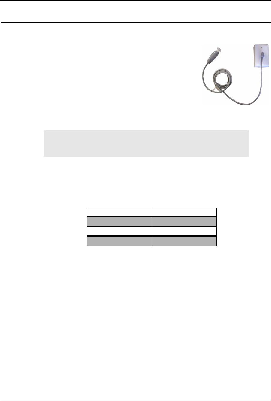
Chapter 2: Installing Transceiver Devices
32 9600 Series Wireless Call System (0510-1078-D) - Hardware Installation Guide
Nurse Call
A Nurse Call is affixed near the bed of the patient. An Assistance
Required alarm event is reported in the Event List when a patient pushes
the button on the Nurse Call cord set. The Nurse Call is supervised; a
routine signal is sent from the transceiver and if the signal is not received
by the system, a Device Fault event is generated in the Event List at the
computer.
Additionally, a Nurse Call Cord Set Tamper alarm is initiated when the Nurse Call cord set is removed from
the Nurse Call. The Nurse Call is powered by a replaceable 3V battery within the Universal enclosure.
To wire the Universal transceiver to the Nurse Call
The 9600 Series Universal transceiver is wired directly to the Nurse Call terminal block using the 22 AWG
wire.
1. Terminate the wires from the Universal transmitter to the Nurse Call per the diagram below.
*The wire labeling is on the underside of the Universal transceiver’s circuit board.
2. Use your fingers to open the front cover of the Universal transceiver by pushing the retaining clip
on the top downward. This allows the hinged cover to drop down and expose the circuit board.
3. Carefully pull the circuit board free from the pins on the enclosure.
4. Pull the plastic battery tab on the Universal transceiver to activate the battery.
5. Return the circuit board onto the two pins.
6. Snap the front cover of the Universal transceiver back into place.
7. Return the Universal transceiver to its place inside the Nurse Call enclosure.
NOTE: The Universal transceiver integrates with the Nurse Call. Refer to “Universal
Transceiver” on page 29 for information on the LED light, tamper functionality and
replacing the battery.
Universal Transceiver* Nurse Call Terminal
NO C1
GND C2
NC S2
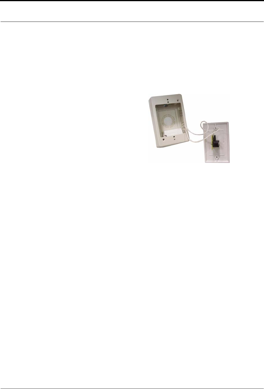
9600 Series Wireless Call System (0510-1078-D) - Hardware Installation Guide 33
Installing Transceiver Devices
To mount the Nurse Call transceiver
1. Using the rear enclosure of the Nurse Call as a template, place it level against the wall at the desired
mounting height and mark the location of the two mounting holes.
2. Center punch each hole and install two nylon wall anchors (included). If the Nurse Call is located
on a concrete wall then you must use the wall anchors designed for use with concrete (not
included).
3. Place the Nurse Call enclosure over the wall anchors in
alignment with the holes in the enclosure and insert two
screws (included).
4. With the Universal transceiver in place, secure the Nurse
Call faceplate to the rear enclosure with two screws. Be
careful not to pinch wires.
To set up the Nurse Call for use
1. Plug in the desired Nurse Call Cord set into the Nurse Call.
2. Activate the Nurse Call by pressing the button.
If the Nurse Call is working properly, the Central Server will sense the Nurse Call when it goes into
alarm and add it to its list of devices.
3. Reset the Nurse Call by pulling the button back to the UP position.
4. At the Central Server, update the Nurse Call information, for example, giving the Nurse Call a
name and/or assigning it to a room or unit. Refer to the “Update Devices” section in the Series 6.0
Software Administrator Guide (PN 0510-1080).
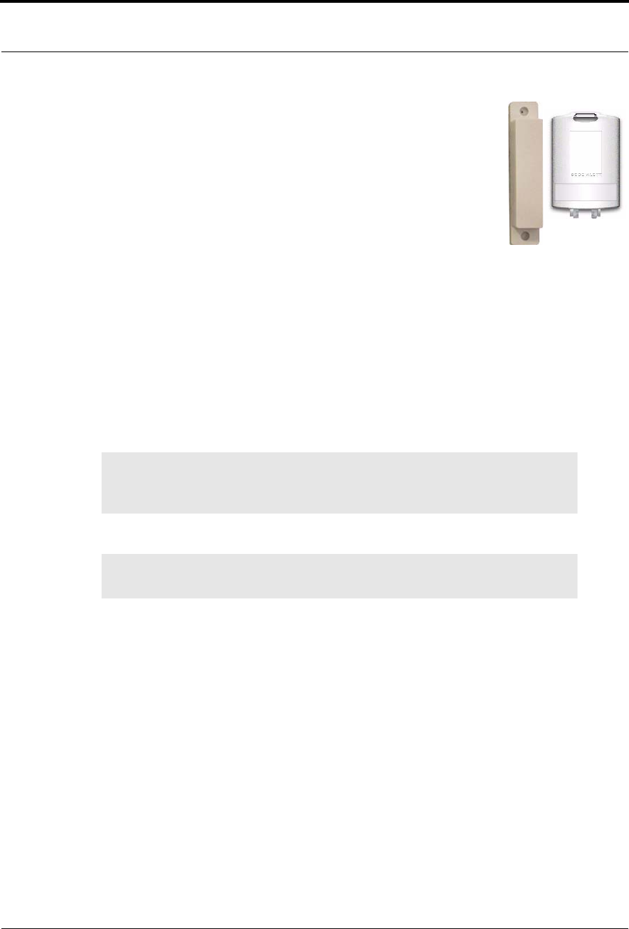
Chapter 2: Installing Transceiver Devices
34 9600 Series Wireless Call System (0510-1078-D) - Hardware Installation Guide
Door/Window Transceiver
A Door/Window transceiver is used to protect a door or window against
unauthorized egress. An Exit alarm event is reported in the Event List when a
monitored door or window is opened. The alarm automatically clears when the
door or window is closed. The Door/Window transceiver is supervised; if no
information is received by the system from the transceiver for a specified number
of minutes, a Device Fault alarm is generated in the Event List at the computer.
The Door/Window transceiver has one (1) LED light. The light is visible when
enclosure door is open (i.e. during installation), but not visible during normal operation when the enclosure
door is closed. The light flashes briefly once every check-in (20 minutes by default) and once each time the
device alarm is triggered or cleared. Green indicates communication with the Router is good; red indicates
communication failure and device is not able to transmit to the Router.
The Door/Window transceiver comes in two pieces: the transceiver enclosure and a magnet. The magnet is
attached directly to the door or window. The transceiver enclosure is mounted on the door or window frame
and can be mounting with the attached adhesive pad or a screw. An alarm triggers when the devices are
separated. The Door/Window transceiver is powered by a replaceable 3V battery within the Universal
enclosure.
To mount the Door/Window magnet to the door or window
1. Determine placement of the magnet. The distance between the reed switch in the transceiver and
the magnet must be no more than 1/2 inch.
2. Using the Door/Window transceiver magnet as a template, place it level against the door or
window and mark the location of the two mounting holes.
3. Drill holes where you made the marks.
4. Line up the holes on the magnet with the newly drilled holes and mount the magnet using the
screws provided.
NOTE: The Universal transceiver integrates with the Door/Window transceiver. Refer to
“Universal Transceiver” on page 29for information on the LED light, tamper
functionality and replacing the battery.
NOTE: When mounting the Door/Window magnet on a door, there is a better sensitivity
if the magnet is mounted closer to the opposite edge from the hinges.
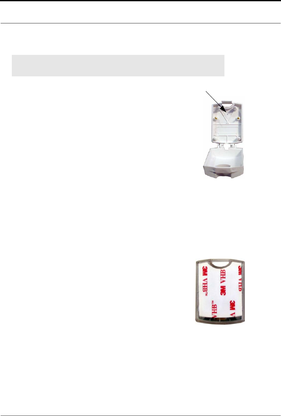
9600 Series Wireless Call System (0510-1078-D) - Hardware Installation Guide 35
Installing Transceiver Devices
To mount the Door/Window transceiver using mounting hole
1. Use your fingers to open the front cover of the transceiver by pushing the
retaining clip on the top downward. This allows the hinged cover to drop
down and expose the circuit board.
2. Carefully pull the circuit board free from the pins on the enclosure.
3. Drill a 1/8 inch mounting hole through the indentation in the transceiver
enclosure.
4. Hold the enclosure against the door/window frame so that when the circuit
board is in place, the internal reed switch faces the magnet on the door.
5. Mark out the mounting hole and drill a 1/16 inch diameter hole where you
made the mark.
6. Line up the hole on the transceiver enclosure with the newly drilled hole
and mount the enclosure to the door frame with a number 6 screw (not
included).
7. Pull the plastic battery tab to activate the battery or refer to the section entitled “To replace the
battery in a Universal transceiver” on page 31.
8. Return the circuit board onto the two pins.
9. Snap the front cover of the transceiver back into place.
To mount the Door/Window transceivers with adhesive pad
The Door/Window transceiver can be attached using an adhesive pad that
can be purchased with the transceiver.
1. Determine where you want to mount the transceiver. The mounting
surface must be clean, dry and free of condensed moisture.
2. Pull the plastic battery tab to activate the battery or refer to the section
entitled “Smoke Detector” on page 39 to insert a new battery.
3. Remove the adhesive plastic guard.
4. Hold the enclosure against the door/window frame so that when the
circuit board is in place, the internal reed switch faces the magnet on the
door.
5. Firmly attach the transceiver to the door/window frame. Ideal application temperature range is 70°F
to 100°F (21°C to 38°C).
6. Press firmly and hold for approximately 10 seconds to activate the pressure sensitive adhesive.
7. After application, the bond strength will increase as the adhesive flows onto the surface. At room
temperature, approximately 50% of ultimate bond strength will be achieved after 20 minutes, 90%
after 24 hours and 100% after 72 hours.
NOTE: Orientate the internal reed switch next to magnet 3/8 inch away. The Universal
transmitter has been tested and shown to work as far as 1/2 inch.
Drill hole here
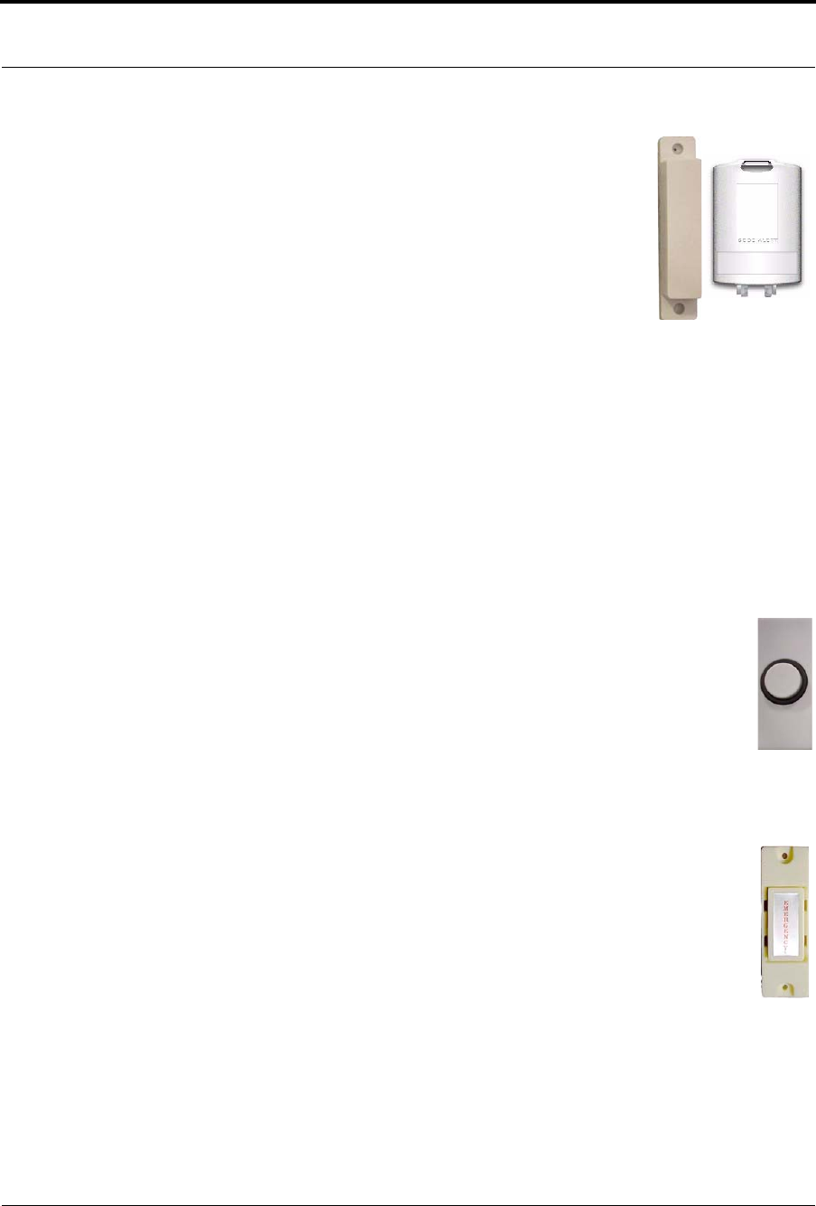
Chapter 2: Installing Transceiver Devices
36 9600 Series Wireless Call System (0510-1078-D) - Hardware Installation Guide
Door/Window Transceiver with Reset Button
If your Door/Window transceiver comes with a reset button, the alarm must be
reset at the door by pressing the reset button once the door/window is closed. The
Door/Window transceiver comes in three pieces: the transceiver enclosure, a
magnet and a reset button. There are two types of reset buttons.
To mount the Door/Window transceiver with Reset Button
1. Mount the Door/Window magnet (refer to “To mount the Door/Window
magnet to the door or window” on page 34). The distance between the
reed switch in the transceiver and the magnet must be no more than 1/2
inch.
2. Mount the Door/Window transceiver (refer to “To mount the Door/
Window transceivers with adhesive pad” on page 35 or “To mount the
Door/Window transceivers with adhesive pad” on page 35). Orientate
the internal reed switch next to the magnet 3/8 inch away.
3. Mount the reset button.
To mount the Reset buttons
There are two types of reset buttons. The Universal transceiver comes pre-wired with 4 feet of 2-
conductor 22 gauge wire. Route wire into door or window jamb and to desired reset button
location.
1. To mount the reset button that has the round push button:
a. Use your fingers to remove the front cover.
b. Using the base of the reset button as a template, place it level against the door or
wall and mark the location of the two mounting holes.
c. Drill holes where you made the marks.
d. Line up the holes on the base of the reset button with the newly drilled holes and
mount the base using the screws provided.
e. Snap the front cover of the reset button back onto the base.
2. To mount the reset button that is labeled EMERGENCY:
a. Using the reset button as a template, place it level against the wall or door and mark
the location of the two mounting holes.
b. Drill holes where you made the marks.
c. Line up the holes on the base of the reset button with the newly drilled holes and
mount the reset button using the screws provided.
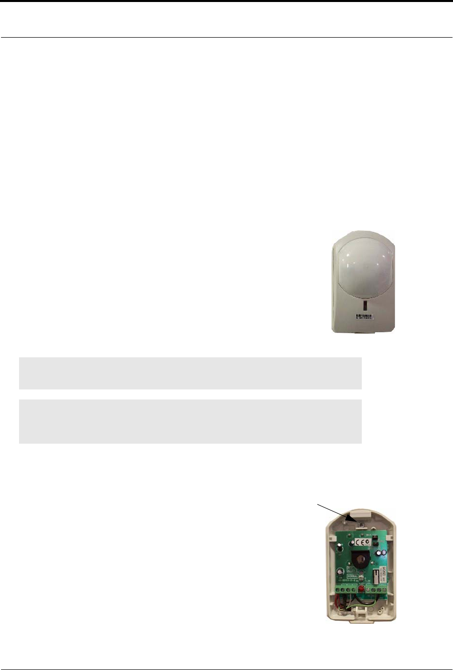
9600 Series Wireless Call System (0510-1078-D) - Hardware Installation Guide 37
Installing Transceiver Devices
To set up the Door/Window transceiver for use
1. Activate the Door/Window transceiver by opening the door or window.
If the transceiver is working properly, the Central Server will sense the Door/Window transceiver
when it goes into alarm and add it to its list of devices.
2. Reset the Door/Window transceiver by closing the door or window and pressing the reset button if
applicable.
3. At the Central Server, update the Door/Window transceiver information, for example, giving it a
name and/or assigning it to a room or unit. Be sure to enable the Inactivity Check-In feature and
select beginning and end times. Refer to the “Update Devices” section in the Series 6.0 Software
Administrator Guide (PN 0510-1080).
PIR Sensor
The Passive Infrared (PIR) Sensor is a passive infrared motion detector that senses
motion in a room or hallway. An Assistance Required alarm event is reported in the
Event List each time the detector is activated.
A PIR Sensor can be supervised; a routine signal is sent from the device and if the signal
is not received by the system, a Device Fault event is generated in the Event List at the
computer. The PIR Sensor is powered by a replaceable 3V battery within the Universal
enclosure.
To mount the PIR Sensor
1. Remove the sensor lens cap from the base the sensor.
2. Using a small Phillips head screwdriver, remove the electronic
assembly enclosure.
3. Hold the base of the PIR Sensor enclosure against the wall at
the desired mounting height.
4. Mark the location of the two mounting holes.
5. Drill holes where the marks were made.
If the drilled holes do not hit a stud wall, you must use wall
anchors.
6. Line up the holes on the base of the enclosure with the newly
drilled holes.
NOTE: More specific mounting and testing specifications can be found in the
manufacturer’s instructions (included with the product).
NOTE: The Universal transceiver integrates with the PIR Sensor. Refer to “Universal
Transceiver” on page 29for information on the LED light, tamper functionality and
replacing the battery.
Unscrew here
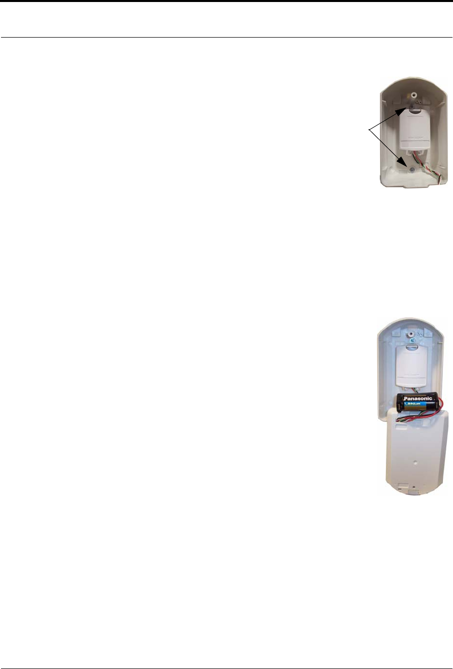
Chapter 2: Installing Transceiver Devices
38 9600 Series Wireless Call System (0510-1078-D) - Hardware Installation Guide
7. Mount the base of the enclosure to the wall using two drywall
screws.
8. If necessary, insert the 3V battery (see “To replace the battery
in a PIR Sensor”).
9. Replace the electronic assembly.
10. Replace the sensor lens cap.
To set up the PIR Sensor for use
1. Activate the PIR Sensor by placing it in alarm (walk in the
motion detection area of the sensor).
2. If the PIR Sensor is working properly, the Central Server will sense the PIR Sensor when it goes
into alarm and add it to its list of devices.
3. The alarm resets once motion is no longer detected in the detection area.
4. At the Central Server, update the PIR Sensor information, for example, giving it a name and/or
assigning it to a room or unit. Refer to the “Update Devices” section in the Series 6.0 Software
Administrator Guide (PN 0510-1080).
To replace the battery in a PIR Sensor
1. With the PIR Sensor facing you, remove the sensor lens cap from the
base the sensor.
2. Using a small Phillips head screwdriver, remove the electronic assembly
enclosure.
3. Remove the old battery.
4. Insert the 3V battery into the battery holder. Be sure to align the positive
(+) end of the battery as marked on the battery holder.
5. Replace the electronic assembly enclosure.
6. Replace the sensor lens cap.
Mounting
holes
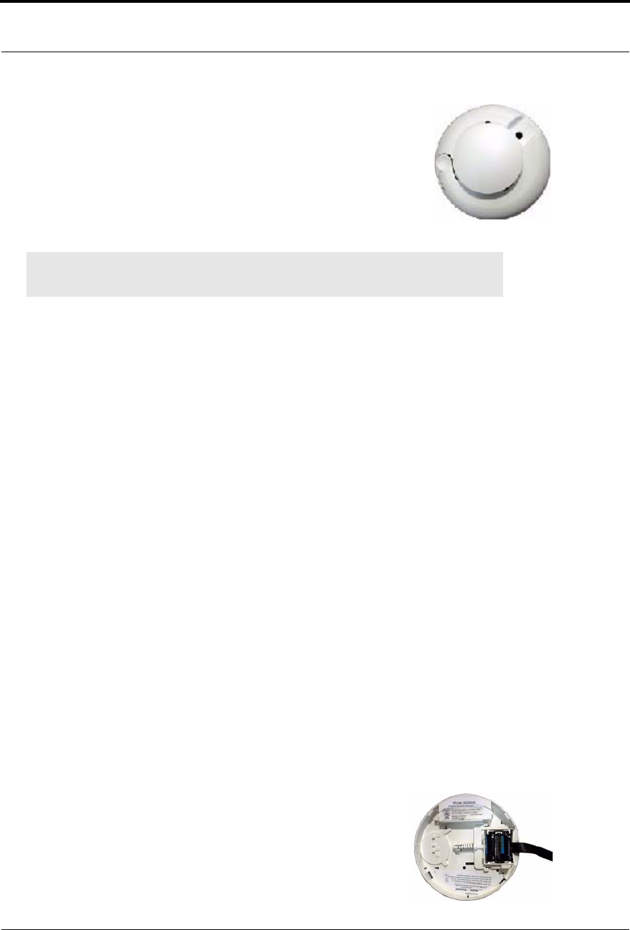
9600 Series Wireless Call System (0510-1078-D) - Hardware Installation Guide 39
Installing Transceiver Devices
Smoke Detector
If your facility is using wireless Smoke Detectors in conjunction with your Series
6.0 System, a Smoke alarm event is reported in the Event List each time a Smoke
Detector is activated. A Smoke Detector is supervised; a routine signal is sent from
the device and if the signal is not received by the system, a Device Fault event is
generated in the Event List at the computer. The Smoke Detector is powered by a
replaceable 3V battery.
To mount the Smoke Detector
1. Remove the detector body from its mounting base by twisting the detector counter clockwise.
2. Hold the base of the Smoke Detector enclosure against the wall at the desired mounting height or
on the ceiling.
3. Mark the location of the two mounting holes.
4. Drill holes where the marks were made.
If the drilled holes do not hit a stud wall, you must use wall anchors.
5. Line up the holes on the base of the enclosure with the newly drilled holes.
6. Mount the base of the enclosure to the wall or ceiling using two drywall screws.
7. If necessary, insert the 3V battery (see “To replace the battery in a Smoke Detector”).
8. Replace the detector back onto its mounting base.
To set up the Smoke Detector for use with your software
1. Activate the Smoke Detector by placing it in alarm. Press the Test/Silence button until the LED
lights or the sounder activates (about 4 seconds).
2. If the Smoke Detector is working properly, the Central Server will sense the Smoke Detector when
it goes into alarm and add it to its list of devices.
3. Reset the alarming device by pressing the Test/Silence button until the LED lights or the sounder
activates (about 4 seconds).
4. At the Central Server, update the Smoke Detector information, for example, giving it a name and/or
assigning it to a room or unit. Refer to the “Update Devices” section in the Series 6.0 Software
Administrator Guide (PN 0510-1080).
To replace the battery in a Smoke Detector
1. With the Smoke Detector facing you, remove the detector body from
its mounting base by twisting the detector counter clockwise.
2. Insert two AA half-size batteries into the battery holder as shown. Be
sure to align the positive (+) end of the battery as marked on the
batteries and battery holder.
3. Replace the detector back onto its mounting base.
NOTE: More specific mounting and testing specifications can be found in the
manufacturer’s instructions (included with the product).

Chapter 2: Installing Transceiver Devices
40 9600 Series Wireless Call System (0510-1078-D) - Hardware Installation Guide
Pendant Transceivers
The Pendant transceiver is a wireless, mobile transceiver that can be worn around the neck or wrist, or
attached to a belt. The protective boot protects the Pendant transceiver against dropping and water ingress.
However to prevent water damage, avoid prolonged submersion and direct contact with a water stream.
The Pendant has one (1) light that is visible from the outside of the enclosure. The light flashes 3 times in
rapid succession when the alarm is triggered or cleared. A green light indicates communication with the
Gateway/Router is good; red indicates communication failure and the device is not able to transmit to the
Gateway/Router.
The Pendant can be supervised; if no information is received by the system from the Gateway for a specified
supervision time, a Check Transmitter alarm is generated in the Event List at the computer. Since the Pendant
is a mobile device, no installation is required.
Activate the Battery
The Pendant is shipped with a replaceable 3V battery. To activate the battery, use your fingers to remove the
back cover and pull off the plastic battery tab. Be sure the battery stays in the battery holder while the plastic
tab is pulled. Additionally, make certain that you are not pressing on the blue button while activating the
battery.
Set up the Pendant
With the Pendant transceiver within range of the system, activate
the Pendant by pressing the blue button.
If the transceiver is working properly, the green light will flash a
series of times, indicating that the Alarm signal is being
transmitted. The system senses the Pendant when it goes into
alarm and adds it to its list of available devices.
NOTE: The default channel for Gateway/Router installation is channel 25. The Pendant will
start its search for a Gateway/Router parent on channel 25. If where you activate the
transceiver is not in the vicinity of channel 25, a series of red light flashes will occur for 2
minutes then the Pendant will search all channels to find a Gateway/Router parent. Once
communication is established a series of green light flashes occur.
Press for 1/2 second
3 green flashes
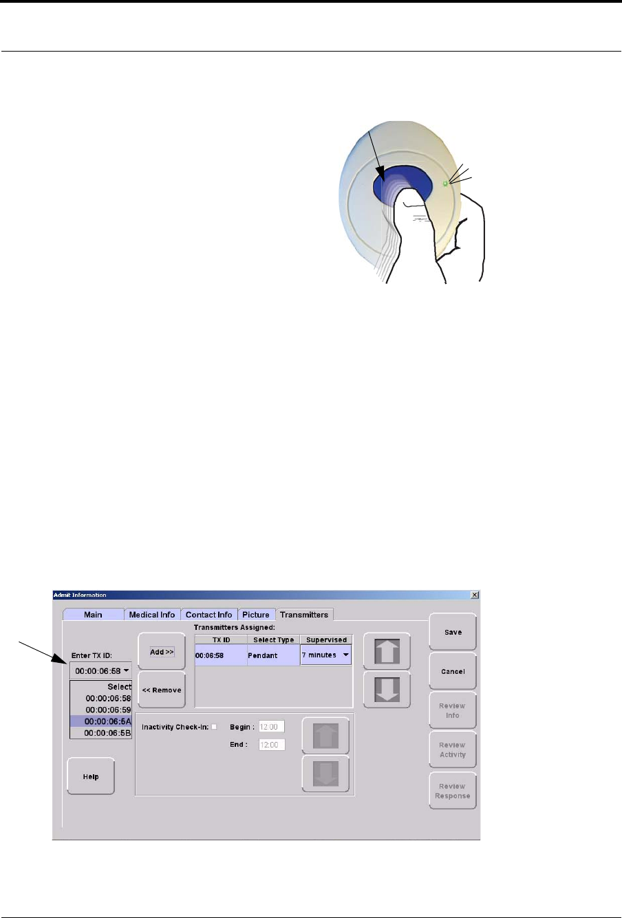
9600 Series Wireless Call System (0510-1078-D) - Hardware Installation Guide 41
Installing Transceiver Devices
Reset the Pendant
Reset the Pendant by rapidly pressing the button six times within
3 seconds.
The green light will flash each time the button is pressed. If the
Pendant is reset properly, the green light will flash a series of
flashes, indicating that the Reset signal is being transmitted.
Verify the Pendant Appears in the System
The pendant is now ready to be assigned. Verify the Pendant appears in the TX ID pull-down by using the
Admit function.
4. Click Admit on the toolbar.
5. If necessary, use your proximity card or magnetic/barcode card or enter your Login and Password
then press Enter or click OK.
The Admit Selection window appears.
6. Select Manual Admit.
7. Select the Transmitters tab.
8. Verify that the TX ID number (last four sets of numbers printed on the Pendant) appears in the
Enter Tx ID: pull-down.
3 green flashes
Press quickly 6 times in 3 seconds

Chapter 2: Installing Transceiver Devices
42 9600 Series Wireless Call System (0510-1078-D) - Hardware Installation Guide
Replace the Battery
RF Technologies uses only Panasonic 3.0 V Coin Cell Lithium Battery
model # CR 2032. This battery provides 10 to 30 percent more power than
other batteries in this size.
To replace a battery in a Pendant transceiver
1. Use your fingers to remove the back cover of the Pendant and
expose the circuit board.
2. If changing the battery, use a small, non-conductive piece of plastic
or wood to push the 3V Lithium coin cell battery from the rear of the battery holder until it pops
free.
3. Press the blue button a few times ensure no charge is remaining in the circuits.
4. Insert the 3V Lithium coin cell battery into the battery holder. Be sure to align the positive (+) end
of the battery as marked on the battery and battery holder.
5. Verify communication by observing the LED light.
6. Snap the back cover back onto the Pendant.
NOTE: Do not use a metal screwdriver or metallic instrument to remove the battery. This
may damage the device.

9600 Series Wireless Call System (0510-1078-D) - Hardware Installation Guide 43
Test the System Operation
Test the System Operation
After all of the components that make up the 9600 Series Wireless Call System are in place, the system-wide
settings are applied, and information specific to at least one transceiver is entered into the database, test the
operation of the entire system. First, confirm that the software is responding; second, ensure that there is
sufficient coverage by the Routers; and third, test the operation of the Supervision function.
To test the software
1. At the Central Server, activate a Pendant transceiver by pressing the button. If the transceiver is
functioning properly, its green light will flash a series of times, indicating that it is sending a signal.
If the software is responding, an Alarm event will be listed on the Event List at the Central Server.
2. Reset the transceiver by rapidly pressing the button six times. The green light will flash each time
the button is pressed. If the transceiver is reset properly, the green light will flash a series of times,
indicating that the Reset signal is being transmitted.
If the software is responding, a Reset event will be listed on the Event List at the Central Server.
To test the system for sufficient coverage
1. At a remote location in the facility, activate a Pendant transceiver by pressing the button. If the
transceiver is functioning properly, its green light will flash a series of times, indicating that it is
sending a signal.
If there is sufficient coverage by the Routers, an Alarm event will be listed on the Event List at the
Central Server.
If your facility is using a paging system in conjunction with your 9600 Series Wireless Call System,
an Alarm message will be received by the pager.
2. Again at a remote location, reset the transceiver by rapidly pressing the button six times. The green
light will flash each time the button is pressed. If the transceiver is reset properly, the green light
will flash a series of times, indicating that the Reset signal is being transmitted.
If there is sufficient coverage by the Routers, a Reset event will be listed on the Event List at the
Central Server.
If your facility is using a paging system in conjunction with your 9600 Series Wireless Call System,
a Reset message will be received by the pager.
3. Repeat these steps at several locations to ensure that the transceiver’s signal is received from all
areas.
To test the operation of the Supervision function
1. Confirm that all of the supervision settings are defined. Refer to the section entitled “Configure
Units” in the Series 6.0 Software Administrator Guide (PN 0510-1080). Make a note of the number
of minutes selected for Transmitter Supervised Time.
2. Confirm that the Supervision setting is enabled for the transceiver(s) used for testing. Refer to the
“Admit” section in the Series 6.0 Software User Guide (PN 0510-1079).
3. Place a number of Pendant transceivers in remote locations throughout the facility.
4. If the Supervision function is operating properly and coverage is adequate, none of the devices will
issue a Missing event at the Central Server.

Chapter 2: Installing Transceiver Devices
44 9600 Series Wireless Call System (0510-1078-D) - Hardware Installation Guide
This page intentionally left blank.

9600 Series Wireless Call System (0510-1078-D) - Hardware Installation Guide 45
Chapter 3
Maintenance
Introduction
The 9600 Series network of devices is partially capable of self-maintenance in the event a device fails. The
system software has four data communications to aid in the maintenance of the network.
1. Reset—force individual Routers, all Routers on a single comports, or all Routers on all
comports to reset.
2. Scan—forces the Gateway and all its Routers to change channel or to execute a rebuild depending
upon what was configured.
3. Configure—individual device (name, supervision rate, channel, layer, etc.).
4. Delete—Remove individual devices from Router tables.
Device Failure
When a single, limited function end device (i.e. Pull Cord, Universal) fails, the following procedure will
remove it from the short address table and allow replacement.
To replace a failed end device
1. Unpower and physically remove the failed device.
2. Delete the device from the Configuration >>Devices window in the software. This results in a
broadcast command from the Gateway to remove this MAC short address for the Router table it
was joined to.
3. With the replacement device within range of the Router, remove the battery tab to activate the
device. The replacement device will automatically search all channels to find a “full function”
device to join.
4. Physically install the replacement device.
5. Alarm and then Reset the device. The system recognizes the device when it goes into alarm and
places it into the Device List for configuration.
6. Configure the replacement device in the software using the same device name as the failed device
previously deleted.
7. If necessary, configure the replacement device into a Unit.
8. If necessary, configure the replacement device into a Room.

Chapter 3: Maintenance
46 9600 Series Wireless Call System (0510-1078-D) - Hardware Installation Guide
Router Failure
When a full function device (Router) fails, its limited function device (i.e. Pull Cord, Universal) will fail to
communicate and automatically search for another Router upon a check-in or alarm.
To replace a failed Router
1. In the software application, click Report on the toolbar and open the Device Tree Report.
2. Sort the Device Tree Report by Comport and print the report.
3. Find the Router and all of its dependant Routers and make a list of these Routers (any Routers that
contain the defective Router name in their path).
4. Remove power from each Router noted in step 3.
a. If AC power is provided by a CPS, turn the CPS output off at this time (all Routers will report
low battery in 5 minutes, but that’s OK).
b. If AC power is provided by individual wall warts, unplug the wall wart for each Router noted
in step 3.
c. Remove battery power (turn battery slide switch to off position) for each Router noted in step
3.
5. In the software, delete all of the Routers noted in step 3 (check delete, click save).
6. Remove battery from each Pull Cord and Universal device that could possibly be within range of
the Routers noted in step 3.
7. Replace the defective Router.
8. Start with just the new Router for the steps below.
9. Apply power to the Router.
a. Apply battery power (turn battery slide switch to on position) for this Router.
b. If AC power is provided by a CPS, leave the CPS output off for now.
c. If AC power is provided by individual wall warts, also plug in the wall wart for this Router.
10. Perform a 15-second reset on this Router (refer to chapter 1 table x if necessary for a 15-second).
11. Wait for a visual indication Router joined the network (dual green blinks for several seconds).
12. Secure Router to the wall.
13. Repeat steps 9-11 for all remaining Routers noted in step 3 (important note: remaining Routers
must be done in order of shortest path to longest path based on the tree report from step 2).
14. Verify each Router noted in step 3 now appears in the software.
15. If AC power is provided by a CPS, re-enable the CPS output at this time.
16. Wait up to the supervision time for a Router and verify none of the Routers are reporting low
battery.

9600 Series Wireless Call System (0510-1078-D) - Hardware Installation Guide 47
Gateway Failure
17. Restore each Pull Cord and Universal from step 6.
a. With battery still removed, press the tamper switch a few times (ensures caps are discharged
and device performs a proper power-up reset).
b. Insert battery.
c. Verify device light indicator blinks green 3 times.
d. Re-mount device.
18. Alarm and clear each Pull Cord and Universal and verify the PC reports each alarm and clear.
19. Open the Device Tree Report and verify that none of the Routers, Pull Cords and Universal devices
are reporting an FFFF short address or have a path that states “Parent is not real”. If the Pull Cords
or Universal devices are, remove their battery, press the tamper switch a few times and replace the
battery. If the Routers are, rebuild the network from that point out using the above procedure or
execute the Rebuild functionality to fix.
Gateway Failure
When a Gateway fails, its Personal Area Network ID (PAN ID) remains in the system. Routers and end
devices search for connectivity to a single Gateway’s PAN ID. The PAN ID is based on the Media Access
Control address (MAC address) of the Gateway.
To replace a failed Gateway
1. Unpower and physically remove the failed Gateway.
a. turn off the Gateway
b. remove the serial cable
c. remove the external antenna
d. remove the board from the enclosure
2. Prepare the replacement Gateway.
a. remove the antenna from the replacement Gateway
b. remove the board from the enclosure
c. place the new Gateway in the old enclosure
3. Execute the Gateway Service Set MAC ID Utility.
4. Connect the replacement Gateway to the service technician’s laptop through the serial port or
PortServer.
5. Start the Set MAC ID Utility.
6. Enter the comport of the Gateway and press Enter.
7. Enter the last eight characters of the MAC ID from the original Gateway and press Enter.
8. Enter the channel number of the original gateway and press Enter.
9. Verify that the programing was successful, then press Q and disconnect the Gateway from the
service technician’s laptop.
10. Perform a 5-second reset on the Gateway.

Chapter 3: Maintenance
48 9600 Series Wireless Call System (0510-1078-D) - Hardware Installation Guide
11. Reattach the external antenna.
12. Connect the power and serial cable on the replacement Gateway.
13. Note the LED sequence on the RS232 status LED. Refer to the LED Sequence Chart for a Service
Replacement (page 12).
14. Physically mount the replacement Gateway.
15. Looking at the Dashboard, verify that the Gateway is checking in every 15 seconds.
16. From the software application, initiate a Reset.
a. go to the Server Management page
b. select the ComPort that the new Gateway is connected
c. click Reset
17. Ensure that all Device Fault events are resolved.
18. Using a RMA form, return the failed Gateway’s circuit board and the replacement Gateway
enclosure to RFT for analysis.
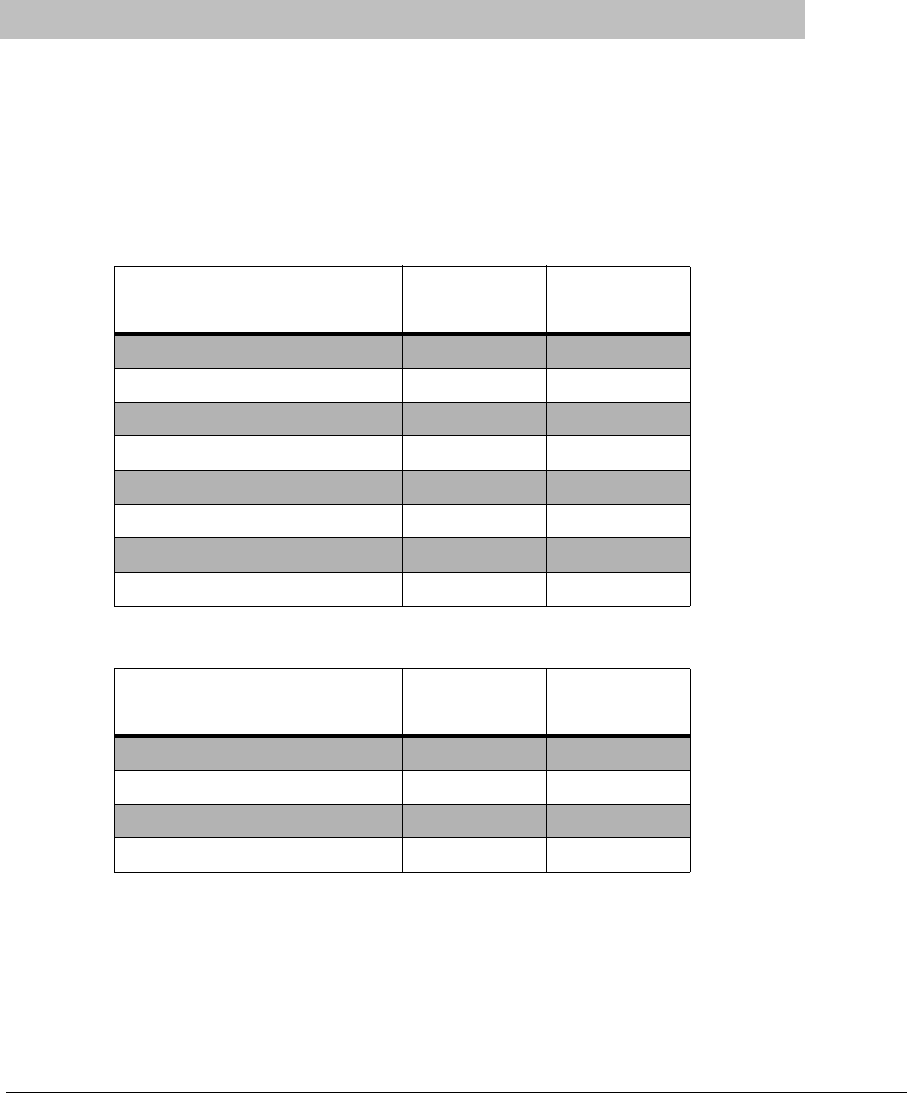
9600 Series Wireless Call System (0510-1078-D) - Hardware Installation Guide 49
Chapter 4
Specifications
Specifications
This section contains information on maximum power cable run lengths for installation of daisy-chained
9600 Series Routers/Gateways. It also provides specifications for the Code Alert 9600 Series devices,
including details about the specific requirements and certifications.
Power Cable Run Lengths
FIGURE 4.1: Powered by CPS
FIGURE 4.2: Powered by Wall Outlet Power Supply
Number of Routers/Gateways CPS
16/2AWG CPS
18/2 AWG
8390' 245'
7450' 280'
6525' 325'
5630' 390'
4785' 490'
31050' 650'
21575' 980'
13150' 1960'
Number of Routers/Gateways 12V @ 1.5A
18/2AWG 9.0V @ 200mA
22/2 AWG
4600'
3740'
21000'
12000' 125'

Chapter 4: Specifications
50 9600 Series Wireless Call System (0510-1078-D) - Hardware Installation Guide
Mesh Network Router/Gateway
Quick Look Display for Quick Look Router
Router/Gateway Specifications
Power 9-15 VDC, .2 A UL Listed
Battery Backup 3.7 V, Lithium Ion Rechargeable Battery, 940 mAH Battery Backup
(10 - 12 hours)
Frequency 2.4 GHz Direct Sequence Spread Spectrum
Frequency Range 2.405 - 2.480 GHz
Bandwidth 5 MHz/Channel
Transmit Power +14 dBm
Operating Temperature 0° F - 100° F
Receive Sensitivity Received Signal, Minimum -72dBm
SNR, Minimum 9dB
Dimensions 4.5" H x 2.7" W x .56" D
Weight 2.9 oz. (82.21g)
Color Off White
Certification FCC, Part 15
Zigbee 802.15.4 Compliant
Quick Look Display Specifications
Size 3.6 x 11.0 x 1.8 inches (View dimensions of display)
Weight 1.7 ounces
Color Light Gray Enclosure
Voltage 12V DC
Display Vacuum Fluorescent (Aqua), 2 lines, 20 Characters per line
Tilt Adjustment Reclines maximum 90 degrees
Current Consumption Specification 400mA
Swivel 330 degree rotation
Included Accessories 4" wall-mount bracket
Certification FCC, Part 15
Zigbee 802.15.4 Compliant

9600 Series Wireless Call System (0510-1078-D) - Hardware Installation Guide 51
Specifications
Pendant Transceiver
Pull Cord
Pendant Transceiver Specifications
Power 3.0V Coin Cell Lithium Battery, CR 2450
Battery Life 3 Months
Low Battery Trouble Level 2.4 VDC
Frequency 2.4 GHz Direct Sequence Spread Spectrum
Frequency Range 2.405 - 2.475 GHz
Bandwidth 5 MHz/Channel
Transmit Power +9 dBm
Receive Sensitivity Received Signal, Minimum -72dBm
SNR, Minimum 9dB
Dimensions 2.13" H x 1.34" W x 60" D
(5.41 cm x 3/40 cm x 12.7 cm)
Weight 1.4 oz. (39.69g)
Water Resistant 4' for 1/2 Hour
Protective Boot Latex-Free Silicon
Color Blue
Certification FCC, Part 15
Zigbee 802.15.4 Compliant
Pull Cord Specifications
Power 3.0V Coin Cell Lithium Battery, CR2450
Battery Life 4-5 year
Low Battery Trouble Level 2.4 VDC
Frequency 2.4 GHz Direct Sequence Spread Spectrum
Frequency Range 2.405 - 2.480 GHz
Transmit Power 0 dBm
Receive Sensitivity Received Signal, Minimum -72dBm
SNR, Minimum 9dB
Dimensions 4.5" H x 2.7" W x 5.6" D
Weight 2.9 oz. (82.21g)
Color Off White
Certification FCC, Part 15
Zigbee 802.15.4 Compliant

Chapter 4: Specifications
52 9600 Series Wireless Call System (0510-1078-D) - Hardware Installation Guide
Nurse Call
Door/Window Transceiver
Nurse Call Specifications
Power 3.0V Coin Cell Lithium Battery, CR 2450
Battery Life 3-5 year
Low Battery Trouble Level 2.4 VDC
Frequency 2.4 GHz Direct Sequence Spread Spectrum
Frequency Range 2.405 - 2.480 GHz
Transmit Power 0 dBm
Receive Sensitivity Received Signal, Minimum -72dBm
SNR, Minimum 9dB
Color Off White
Certification FCC, Part 15
Zigbee 802.15.4 Compliant
Door/Window Transceiver Specifications
Power 3.0V Coin Cell Lithium Battery, CR 2450
Battery Life 2 year
Low Battery Trouble Level 2.4 VDC
Frequency 2.4 GHz Direct Sequence Spread Spectrum
Frequency Range 2.405 - 2.480 GHz
Transmit Power 0 dBm
Receive Sensitivity Received Signal, Minimum -72dBm
SNR, Minimum 9dB
Dimensions 2.2" H x 1.8" W x 8" D
Weight .68 oz.
Color Off White
Certification FCC, Part 15
Zigbee 802.15.4 Compliant
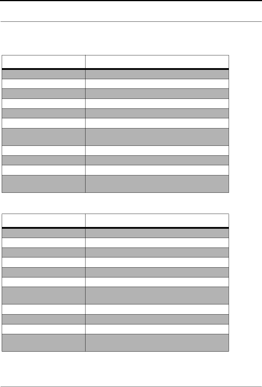
9600 Series Wireless Call System (0510-1078-D) - Hardware Installation Guide 53
Specifications
PIR Sensor
Smoke Detector
PIR Sensor Specifications
Power 3.0V Lithium Battery
Battery Life 1-2 year (based on use)
Low Battery Trouble Level 2.4 VDC
Frequency 2.4 GHz Direct Sequence Spread Spectrum
Frequency Range 2.405 - 2.480 GHz
Transmit Power 0 dBm
Receive Sensitivity Received Signal, Minimum -72dBm
SNR, Minimum 9dB
Dimensions 3" H x 4.38" L x 2.38" W
Weight .40 lbs
Color Off White
Certification FCC, Part 15
Zigbee 802.15.4 Compliant
Smoke Detector Specifications
Power Two 3.0V Lithium Batteries
Battery Life 1-2 year
Low Battery Trouble Level 2.4 VDC
Frequency 2.4 GHz Direct Sequence Spread Spectrum
Frequency Range 2.405 - 2.480 GHz
Transmit Power 0 dBm
Receive Sensitivity Received Signal, Minimum -72dBm
SNR, Minimum 9dB
Dimensions 2.5" H x 5.5" in Diameter
Weight .60 lbs
Color Off White
Certification FCC, Part 15
Zigbee 802.15.4 Compliant

Chapter 4: Specifications
54 9600 Series Wireless Call System (0510-1078-D) - Hardware Installation Guide
Universal Transceiver
Universal Transceiver Specifications
Power 3.0V Coin Cell Lithium Battery, CR 2450
Battery Life 2 year
Low Battery Trouble Level 2.4 VDC
Frequency 2.4 GHz Direct Sequence Spread Spectrum
Frequency Range 2.405 - 2.480 GHz
Transmit Power 0 dBm
Receive Sensitivity Received Signal, Minimum -72dBm
SNR, Minimum 9dB
Dimensions 2.2" H x 1.8" W x 8" D
Weight .64 oz.
Color Off White
Certification FCC, Part 15
Zigbee 802.15.4 Compliant