R F Technologies SP3FSZ24 Wireless Nurse Call and Security Device User Manual 0510 1099 Rev I Installation Guide
R F Technologies Inc Wireless Nurse Call and Security Device 0510 1099 Rev I Installation Guide
0510-1099-Rev I_Installation Guide

Quick Response® Premiere Wireless Call
System
Hardware Installation Guide

© 2017 RF Technologies, Inc. All specifications subject to change without notice.
All Rights Reserved. No Part of this work may be reproduced or copied in any form or by any means without written permission
from RF Technologies, Inc.
® and ™ indicate trademarks owned by RF Technologies, Inc.

Contents
Quick Response Premiere Hardware Installation Guide Page 1 of 77
0510-1099-I
Contents
CONTENTS ............................................................................................................................................. 1
WARNINGS / CAUTIONS / COMPLIANCE ............................................................................................ 5
Warnings .......................................................................................................................................... 5
Cautions ........................................................................................................................................... 7
Bio-Incompatibility Notice ................................................................................................................. 7
Federal Communication Commission (FCC) Compliance .............................................................. 8
FCC – Part 15 ............................................................................................................................ 8
Radiation Exposure Statement for Mobile Devices ................................................................... 8
Radiation Exposure Statement for Portable Devices ................................................................ 9
Industry Canada Compliance ........................................................................................................... 9
Detachable Antenna Operation ............................................................................................... 10
Licence-Exempt RSSs ............................................................................................................. 10
PREFACE .............................................................................................................................................. 11
Introduction .................................................................................................................................... 11
Intended Audience ......................................................................................................................... 11
Additional Documentation .............................................................................................................. 11
Contact Information ........................................................................................................................ 12
Product Warranty ........................................................................................................................... 12
CHAPTER 1 – INSTALLING HARDWARE COMPONENTS ............................................................... 13
Introduction .................................................................................................................................... 13
Installation Checklist ...................................................................................................................... 13
System Components ...................................................................................................................... 14
Central Server.......................................................................................................................... 14
Gateway ................................................................................................................................... 15
Router ...................................................................................................................................... 18
Quick Look ............................................................................................................................... 20
32 Channel Controller .............................................................................................................. 22
Dome Lights............................................................................................................................. 23
Wiring Diagram ........................................................................................................................ 26
Power Cable Run Lengths ....................................................................................................... 27
32 Channel Controller Configuration ....................................................................................... 27
Channels .................................................................................................................................. 29
Router Depth ........................................................................................................................... 30
Gateway / Router Reset Button ............................................................................................... 33
LED Sequence ........................................................................................................................ 34
Troubleshooting ............................................................................................................................. 34
End Device Failure .................................................................................................................. 35
Cloning ..................................................................................................................................... 35
Router Failure .......................................................................................................................... 35

Contents
Page 2 of 77 Quick Response Premiere Hardware Installation Guide
0510-1099-I
Gateway Failure ...................................................................................................................... 37
CHAPTER 2 – INSTALLING END DEVICES ....................................................................................... 39
Introduction .................................................................................................................................... 39
Call Stations ................................................................................................................................... 39
Display ..................................................................................................................................... 39
Mounting .................................................................................................................................. 40
Add Retention .......................................................................................................................... 41
Nurse Call ................................................................................................................................ 41
Push Button Emergency Call ................................................................................................... 42
Pull Cord .................................................................................................................................. 42
Pull Cord with Check-In ........................................................................................................... 43
Battery Replacement ............................................................................................................... 44
Universal Transceiver .................................................................................................................... 44
Display ..................................................................................................................................... 44
Mounting .................................................................................................................................. 45
Battery Replacement ............................................................................................................... 46
Tamper .................................................................................................................................... 46
Door/Window Transceiver .............................................................................................................. 47
Display ..................................................................................................................................... 47
Mounting .................................................................................................................................. 47
Door/Window Transceiver w/Reset Button .................................................................................... 49
Mounting .................................................................................................................................. 49
Battery Replacement ............................................................................................................... 50
Pendants ........................................................................................................................................ 52
Display ..................................................................................................................................... 52
Activate .................................................................................................................................... 52
Battery Replacement ............................................................................................................... 53
LED Light Indicators ....................................................................................................................... 55
Carbon Monoxide ........................................................................................................................... 56
Wiring ....................................................................................................................................... 56
Activate .................................................................................................................................... 56
Testing the System ........................................................................................................................ 57
Com Port Mapping ................................................................................................................... 57
Device Configuration ............................................................................................................... 57
Dashboard ............................................................................................................................... 58
Device Tree Report ................................................................................................................. 58
Software Operation .................................................................................................................. 58
Monitor System ........................................................................................................................ 59
CHAPTER 3 – SPECIFICATIONS ........................................................................................................ 61
Introduction .................................................................................................................................... 61
Central Power Supply .................................................................................................................... 61
Universal Power Supply ................................................................................................................. 62
Gateway ......................................................................................................................................... 63
Router............................................................................................................................................. 64

Contents
Quick Response Premiere Hardware Installation Guide Page 3 of 77
0510-1099-I
Quick Look Display ........................................................................................................................ 65
32 Channel Controller .................................................................................................................... 67
Dome Lights ................................................................................................................................... 68
Call Stations ................................................................................................................................... 69
Universal Transceiver .................................................................................................................... 70
Door/Window Transceiver .............................................................................................................. 71
Pendant .......................................................................................................................................... 72
Application Disruption Alarm .......................................................................................................... 73
PIR Motion Sensor ......................................................................................................................... 74
Smoke Detector ............................................................................................................................. 75
Carbon Monoxide Alarm ................................................................................................................ 76
REVISION HISTORY ............................................................................................................................. 77

Contents
Page 4 of 77 Quick Response Premiere Hardware Installation Guide
0510-1099-I
This page intentionally left blank

Warnings / Cautions / Compliance
Quick Response Premiere Hardware Installation Guide Page 5 of 77
0510-1099-I
Warnings / Cautions / Compliance
It is important for your facility to implement and enforce the following WARNINGS and CAUTIONS in
order to keep all equipment functioning properly. Disregarding the information and instructions in this
document is considered abnormal use and may result in injury or system failure.
Warnings
ACCESSORIES (SUPPLIES)—To ensure resident safety and proper
operation of equipment, use only parts and accessories manufactured or
recommended by RF Technologies, Inc. Parts and accessories not
manufactured or recommended by RF Technologies, Inc. may not meet
the requirements of the applicable safety and performance standards.
Failure to use the components and supplies specified by RF
Technologies, Inc. may result in equipment and/or system failure.
EXPLOSION HAZARD—These devices should not be used in the
presence of flammable gas mixtures. It should also not be used in oxygen
enriched atmospheres.
INSTALLATION AND CONFIGURATION—It is the responsibility of the
facility to follow the installation instructions carefully, as outlined in the
applicable system guides, and to use the components and supplies
specified by RF Technologies, Inc. for all installations.
Failure to use the components and supplies specified by RF
Technologies, Inc. may result in equipment and/or system failure.
INSTRUCTIONS FOR SET UP AND USE—It is the responsibility of the
facility to follow the instructions for set up and use carefully, as outlined in
this manual, and to use the components and supplies specified by RF
Technologies, Inc. for set up and use. Do not attempt to use extension
cords or other equipment not supplied by RF Technologies, Inc.
Failure to use the components and supplies specified by RF
Technologies, Inc. may result in equipment and/or system failure.
STATIC DISCHARGE—Do not touch the conductor portion of any
conductor or port. Damage to the device may result.
STRANGULATIONS AND TRIPPING HAZARD—Due to the possibility of
strangulation, all cables and cords should be routed away from the
resident’s throat. Cables and cords must be routed in a way to prevent
tripping hazards.

Warnings / Cautions / Compliance
Page 6 of 77 Quick Response Premiere Hardware Installation Guide
0510-1099-I
SYSTEM INSPECTION—It is the responsibility of the facility to establish
and facilitate a regular inspection schedule for your system. RF
Technologies, Inc. recommends quarterly inspections of your system for
safety and performance by a qualified RF Technologies, Inc.
representative.
To arrange for a quarterly inspection by RF Technologies, Inc., call our
Technical Support Department at (800)-669-9946 or (262) 790-1771.
Failure to provide regular inspection of these products may result in
equipment and/or system failure.
SYSTEM MAINTENANCE AND TESTING—It is the responsibility of the
facility to establish and facilitate a regular maintenance schedule for your
system, as outlined in the applicable system guides. This includes regular
inspection, testing, and cleaning. RF Technologies, Inc. recommends
monthly maintenance and testing of your system. It is also recommended
that your facility keep records of maintenance and test completions.
Failure to provide regular maintenance and testing of these products
may result in equipment and/or system failure.
SYSTEM WIRING—All permanent supply connections must be done in
accordance with National Electric Code, NFPA 70.
USER TRAINING—Only users who have received adequate training on
the use of the system, as outlined in this manual, should use the system.
It is the responsibility of the facility to ensure all users have been trained.
Failure to adequately train employees may cause system failure due
to user error. In addition, incorrect use of the equipment may also
result in system failure.
MR UNSAFE
All RF Technologies transmitters, pendants and banding material
“PRODUCT” have been determined to be MR Unsafe as defined by
ASTM F 2503-05. Use of “PRODUCT” in a Magnetic Resonance Imaging
system will cause injury to residents and staff, MR system malfunction or
“PRODUCT” malfunction. Do not bring “PRODUCT” into the MR system
area and follow your facilities policies to classify and label “PRODUCT” as
MR Unsafe.

Warnings / Cautions / Compliance
Quick Response Premiere Hardware Installation Guide Page 7 of 77
0510-1099-I
Cautions
WORN OR DAMAGED PARTS—If the control unit pads or cables are
worn or damaged, you must have the product serviced. For more
information, see the section entitled “Service and Return.”
DISPOSAL—At the end of their service life the products described in this
manual, as well as accessories (i.e. lithium batteries, banding material,
disposable pads, etc.), must be disposed of in compliance with all
applicable federal, state and local guidelines regulating the disposal of
products containing potential environmental contaminants. Dispose of the
packaging material by observing the applicable waste control regulations.
RESIDENT GENERATED ALARMS—Do not rely exclusively on resident
generated alarms for resident care and safety. The alarm function of
equipment in the possession of residents must be verified periodically and
regular resident surveillance is recommended.
RESIDENT MONITORING—The most reliable method of resident
monitoring combines close personal surveillance with correct operation of
monitoring equipment. It is the responsibility of the facility to periodically
check on residents in possession of RF Technologies, Inc.'s equipment
(i.e. Pendants, Pull Cords, Control Units) to mitigate risk of inappropriate
use of equipment or strangulation and stumbling hazards from cables and
cords.
PRODUCT WARRANTIES—Failure to follow the Warnings and Cautions
in this guide voids any and all Product Warranties.
Bio-
Incompatibility
Notice
Do not use Pendants with people that have sensitivities or allergies to
device materials. The device materials include Acrylonitrile butadiene
styrene (ABS), Silicon, Rubber, and Neoprene.

Warnings / Cautions / Compliance
Page 8 of 77 Quick Response Premiere Hardware Installation Guide
0510-1099-I
Federal Communication Commission (FCC) Compliance
FCC – Part 15
This device complies with Part 15 of the FCC Rules. Operation is subject
to the following two conditions: (1) this device may not cause harmful
interference, and (2) this device must accept any interference received,
including interference that may cause undesired operation of the device.
This equipment generates, uses, and can radiate radio frequency energy
and, if not installed and used in accordance with the instruction manual,
may cause harmful interference to radio communications. Operation of
this equipment in a residential area is likely to cause harmful interference
in which case the user will be required to correct the interference at his
own expense. Changes or modifications not expressly approved by RF
Technologies Inc. voids the user’s authority to operate the equipment.
NOTE: This equipment has been tested and found to comply with the
limits for a Class A digital device, pursuant to Part 15 of the FCC Rules.
These limits are designed to provide reasonable protection against
harmful interference when the equipment is operated in a commercial
environment. This equipment generates, uses, and can radiate radio
frequency energy and, if not installed and used in accordance with the
instruction manual, may cause harmful interference to radio
communications. Operation of this equipment in a residential area is likely
to cause harmful interference in which case the user will be required to
correct the interference at his or her own expense.
Radiation
Exposure
Statement for
Mobile Devices
(For the Pull Cord model 0800-0285 and model 0800-0317; Universal
Transceiver model 0800-0301/0800-0303/0800-0304; Extended Range
Router model 0800-0351/0800-0445/0800-0550; Gateway with External
Antenna model 0800-0354/0800-0446/0800-0551; Router model 0800-
0364; Asset Transceivers model 0800-0286 and model 0800-0302 and
Motion Control Unit model 0800-0350)
This equipment complies with FCC and IC radiation exposure limits set
forth for an uncontrolled environment. This equipment should be installed
and operated with minimum distance 20cm between the radiator and your
body. This transceiver must not be co-located or operating in conjunction
with any other antenna or transceiver except in accordance with
FCC/ISED Canada multi-transmitter product procedures.
Cet équipement est conforme aux normes FCC et IC l'exposition aux
rayonnements limites établies pour un environnement non contrôlé. Cet
équipement doit être installé et utilisé avec une distance minimale de 20
cm entre le radiateur et votre corps. Cet émetteur-récepteur doit être situé
à côté ou fonctionner avec toute autre antenne ou émetteur-récepteur
qu'en conformité avec la réglementation FCC/indicateurs du Canada
produit émetteur multi-procédures.

Warnings / Cautions / Compliance
Quick Response Premiere Hardware Installation Guide Page 9 of 77
0510-1099-I
Radiation
Exposure
Statement for
Portable
Devices
(For the Call Pendants model 0800-0375 / 0800-0590)
This equipment complies with FCC and IC radiation exposure limits set
forth for an uncontrolled environment. This equipment is in direct contact
with the body of the user under normal operating conditions. This
transceiver must not be co-located or operating in conjunction with any
other antenna or transceiver except in accordance with FCC/ISED
Canada multi-transmitter product procedures.
Cet équipement est conforme aux normes FCC et IC l'exposition aux
rayonnements limites établies pour un environnement non contrôlé. Cet
équipement est en contact direct avec le corps de l'utilisateur dans les
conditions normales de fonctionnement. Cet émetteur-récepteur doit être
situé à côté ou fonctionner avec toute autre antenne ou émetteur-
récepteur qu'en conformité avec la réglementation FCC/indicateurs du
Canada produit émetteur multi-procédures.
Industry Canada
Compliance
Changes or modifications not expressly approved by RF Technologies
Inc. could void the user’s authority to operate the equipment. The Term
“IC” before the radio certification number only signifies that Industry
Canada technical specifications were met.
This device complies with Industry Canada license-exempt RSS
standard(s). Operation is subject to the following two conditions: (1) this
device may not cause harmful interference, and (2) this device must
accept any interference received, including interference that may cause
undesired operation of the device.
Le présent appareil est conforme aux CNR d'Industrie Canada
applicables aux appareils radio exempts de licence. L'exploitation est
autorisée aux deux conditions suivantes : (1) l'appareil ne doit pas
produire de brouillage, et (2) l'utilisateur de l'appareil doit accepter tout
brouillage radioélectrique subi, même si le brouillage est susceptible d'en
compromettre le fonctionnement.
Under Industry Canada regulations, this radio transmitter may only
operate using an antenna of a type and maximum (or lesser) gain
approved for the transmitter by Industry Canada. To reduce potential radio
interference to other users, the antenna type and its gain should be so
chosen that the equivalent isotropically radiated power (e.i.r.p.) is not
more than that necessary for successful communication.
Conformément à la réglementation d'Industrie Canada, le présent
émetteur radio peut fonctionner avec une antenne d'un type et d'un gain
maximal (ou inférieur) approuvé pour l'émetteur par Industrie Canada.
Dans le but de réduire les risques de brouillage radioélectrique à
l'intention des autres utilisateurs, il faut choisir le type d'antenne et son
gain de sorte que la puissance isotrope rayonnée équivalente (p.i.r.e.) ne
dépasse pas l'intensité nécessaire à l'établissement d'une communication
satisfaisante.

Warnings / Cautions / Compliance
Page 10 of 77 Quick Response Premiere Hardware Installation Guide
0510-1099-I
Detachable
Antenna
Operation
The following radio transmitters: Extended Range Router models 0800-
0351/0800-0445/0800-0550; Gateway with External Antenna models
0800-0354/0800-0446/0800-0551, Model 0330-0044 (2.2dBi gain) have
been approved by Industry Canada to operate with the antenna types
listed below with the maximum permissible gain indicated. Antenna types
not included in this list, having a gain greater than the maximum gain
indicated for that type, are strictly prohibited for use with this device.
Le présent émetteur radioidentifier le dispositif par son numéro de
certification a été approuvé par Industrie Canada pour fonctionner avec
les types d'antenne énumérés ci-dessous et ayant un gain admissible
maximal. Les types d'antenne non inclus dans cette liste, et dont le gain
est supérieur au gain maximal indiqué, sont strictement interdits pour
l'exploitation de l'émetteur.
Licence-
Exempt RSSs
This device complies with Industry Canada’s licence-exempt RSSs.
Operation is subject to the following two conditions: (1) this device may
not cause interference, and (2) this device must accept any interference,
including interference that may cause undesired operation of the device.
Cet appareil est conforme à l'Industrie Canada RSSs exempts de licence.
Le fonctionnement est soumis aux deux conditions suivantes : (1) cet
appareil ne doit pas causer d'interférences et (2) cet appareil doit
accepter toute interférence, y compris les interférences pouvant
provoquer un fonctionnement indésirable de l'appareil.

Preface
Quick Response Premiere Hardware Installation Guide Page 11 of 77
0510-1099-I
Preface
Introduction
This guide provides detailed information about the hardware components
and devices of the Quick Response Premiere Wireless Call System. It
provides instructions about installation as well as specific requirements for
mounting components that make up the system. The Quick Response
Premiere Wireless Call System is to be professionally installed.
The system immediately notifies staff when a resident requires attention,
and provides details that are essential in responding quickly and
competently to a resident’s needs. The system offers a variety of devices,
each of which interfaces with the Central Server to ensure that when a
resident is in need, staff is alerted.
A Quick Response Premiere device may be worn by a resident; it could
be mounted to a wall where it is easy to access; it could even be used in
conjunction with other systems such as the Wanderer Monitoring System
(exit controllers and electromagnetic door locks).
Devices send data to the Central Server on a regular basis. When an
event occurs that warrants a response, staff is alerted by an audible alarm
from the Central Server, a message is displayed on-screen, and the
designated staff is summoned to respond to the situation. Staff can also
be notified of an event via pager or phone.
Intended
Audience
This guide is intended for users who install components of the Quick
Response Premiere Wireless Call System, in conjunction with the
applicable Series Software. It includes detailed information about the
hardware installation and setup of various components that interface with
the applicable Series Software.
WARNING: Before you begin any new upgrades, repairs or maintenance,
RF Technologies recommends that you back up the MSSQL and .DB Flat
File databases on a removable media, such as an external drive, to be
copied to a new or different computer if necessary. Refer to the Database
Archive and Backup Service Guide (0510-0306).
Additional
Documentation
Documentation for your system is available in Portable Document Format
(PDF) on the System Documentation CD-ROM. Please contact your RF
Technologies sales representative for replacement CD-ROMs.

Preface
Page 12 of 77 Quick Response Premiere Hardware Installation Guide
0510-1099-I
Contact
Information
For more information about RF Technologies, Inc. products, go to
www.rft.com.
For technical support, contact the Technical Support Team at (800) 669-
9946 or (262) 790-1771.
For questions or comments about the System Documentation, contact the
RF Technologies Technical Publications team at techpubs@rft.com.
Product
Warranty
Product Warranty information can be found on the System Documentation
CD or with your original system proposal and invoice.

Chapter 1 – Installing Hardware Components
Quick Response Premiere Hardware Installation Guide Page 13 of 77
0510-1099-I
Chapter 1 – Installing Hardware Components
Introduction
The basic components of the system consist of the Central Server, the
Gateway, the Router and the transceiver devices. The Central Server is a
RF Technologies configured computer that runs the software. It contains
the database and provides communication with the devices in the system.
The Computer Monitoring Station must be permanently located at the
central nurse’s station.
Depending on your configuration, the system can include several Client
computers. The Client computers allow the user to perform such functions
as admitting, discharging, and clearing alarms. Each Client computer
includes a touchscreen monitor that displays alarms as they occur on a
floor plan of the facility.
Although this manual describes the many various devices that can be
included, the minimum system configuration must consist of no less than
the following devices:
One patient station (Pull Cord, Nurse Call Jack and Cord or Pendant)
Dome Light
Gateway
Router
32 Zone Relay Output Assembly
Computer Monitoring Station
This chapter provides detailed information about setting up the Central
Server and installing hardware components to use in conjunction with the
software. It also provides an Installation Checklist to assist with the
installation process.
When installing product, you must follow standard accepted safety
practices such as wearing safety glasses.
Before cutting openings or drilling holes through walls, you must verify
that you will not strike any wiring or plumbing.
Installation
Checklist
1. Read this guide in its entirety before proceeding with the installation.
2. Review the floor plan of the facility and make sure the equipment
shipped to you matches what is shown on the floor plan.
3. Walk through the facility and determine the physical location of all
components of your system, compared to the floor plan.
4. Determine how the Gateway(s) and Routers are going to be powered
(refer to the Power Cable Run Lengths chart under Specifications to
choose the appropriate wire size)

Chapter 1 – Installing Hardware Components
Page 14 of 77 Quick Response Premiere Hardware Installation Guide
0510-1099-I
5. Install System Components
Central Server
If applicable in your facility, Client computer(s)
Gateway
Routers
6. Install transceiver devices. Transceiver devices transmit and receive
data.
Mount all fixed devices (i.e. Pull-Cords, Smoke Detectors,
Door/Window transceivers)
Enter transceiver information into the software (refer to the
applicable Series Software User and Administrator Guides)
7. Using the software, define the options, or system-wide settings to be
applied to your facility’s Quick Response Premiere Wireless Call
System.
8. Test the operation of the system.
Test the software
Test the system for sufficient coverage
Test the operation of the Supervision function
System Components
Central Server
The first step in the installation of the hardware components is to set up
the Central Server. The Central Server computer can be placed on a flat
surface, and the monitor may be mounted on a wall. Optional wall
mounting kits are available from RF Technologies (PN 0120-0097 and
0120-0098). These mounting kits comply with VESA mounting standards.
Please follow the manufacturer's instructions for mounting the monitor.
WARNING: When installing the Central Server, proper
placement/mounting of the server is important. Adequate precautions
must be taken to prevent the server from falling, causing injury to persons.
Cables must be routed in a way to prevent tripping hazards.
Any rack mounted Central Server must be installed in a controlled
environment that maintains temperature between 50°F and 95°F and
humidity between 20% and 50%.
1. Check to see that you have all the required equipment for setting up
the Central Server:
15 Gigabytes (GB) of free hard disk space
RF Technologies configured computer
Monitor
Keyboard
Mouse
UPS (uninterruptable power supply)
Chapter 1 – Installing Hardware Components
Quick Response Premiere Hardware Installation Guide Page 15 of 77
0510-1099-I
Printer (optional)
Remote connection hardware (if applicable)
2. Set up all the components of the Central Server.
3. Plug the components into the back of the Central Server (monitor,
keyboard, mouse, printer).
4. Power the Central Server using a Plug-in Power Supply with a battery
backup unit (UPS). The UPS should be plugged into a backup
generator outlet.
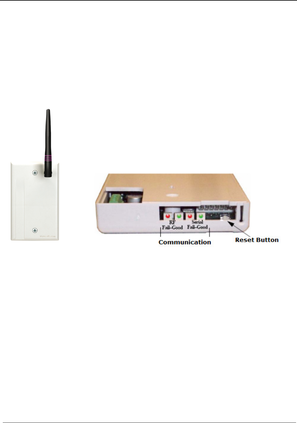
Gateway
The Gateway receives signals from Routers and transceiver devices and
sends them to the Central Server. The Gateway can be supervised; if no
information is received by the system from the Gateway for a specified
amount of time, a Device Fault alarm is generated in the Event List at the
computer.
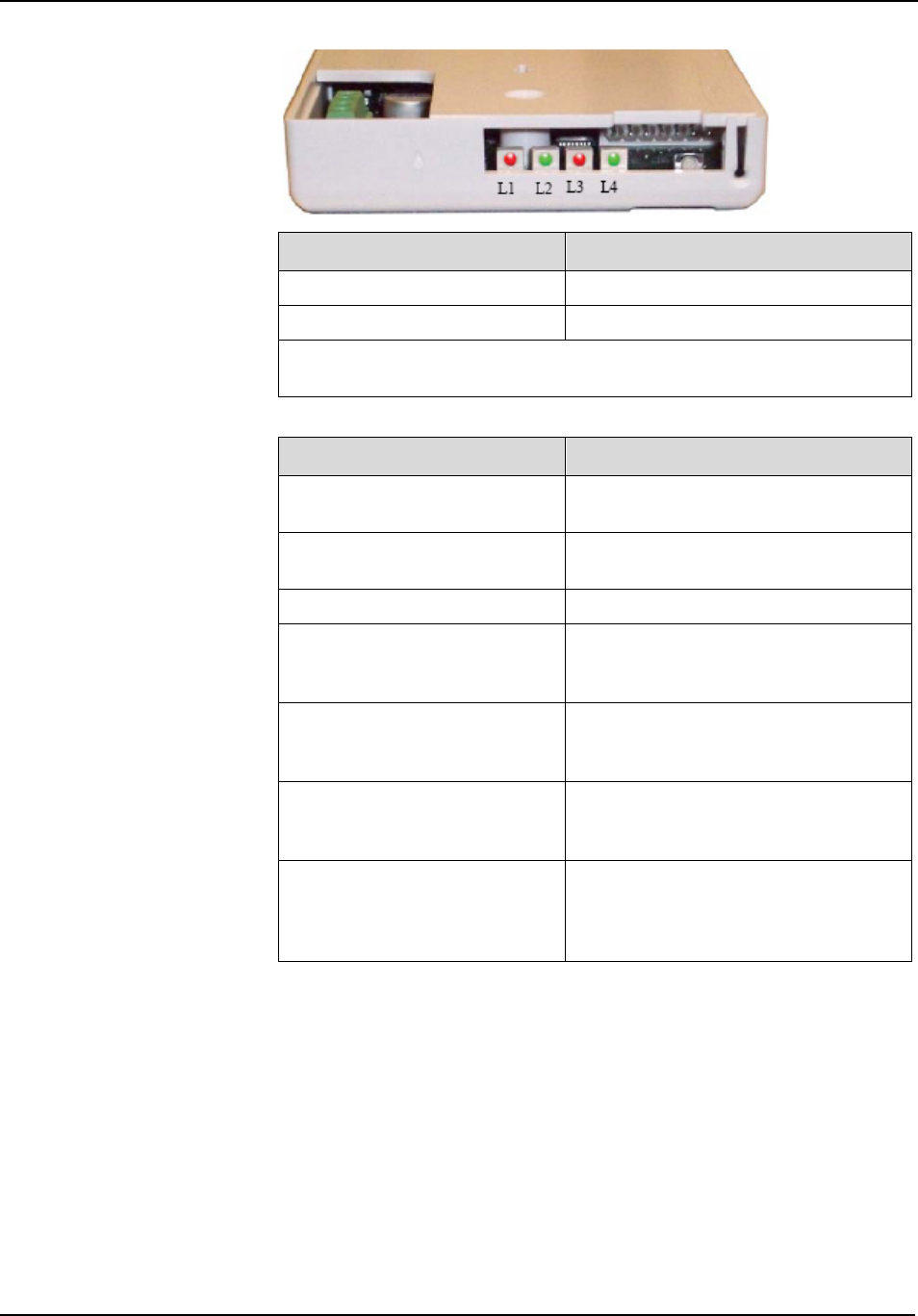
The Gateway has four (4) single-color LED lights; two green and two red.
For more information on LED lights and LED sequence refer to the LED
Sequence section.
Bottom view of the gateway
RF Fail-Good: The two sets of lights furthest from the Reset Button
indicate transceiver device communication status. These set of lights flash
briefly (once) every check-in (15 seconds by default) and when data is
received or transmitted.
Green indicates communication is good (received data is
formatted properly or the transmitted data was sent successfully).
Red indicates communication failure (received data has an error
or the transmitted data was NOT sent successfully).
Serial Fail-Good: The two sets of lights closest to the Reset Button
indicate RS232 communication status with the Central Server. These set
of lights flash briefly (once) when data is transmitted via an external
RS232 device to the Central Server.
Green indicates communication is good (transmission data
acknowledged by the Central Server).
Red indicates communication failure (transmission data NOT
acknowledged by the Central Server).
A repeating, dim red LED flash (flashes once per second)
indicates the device operating normally.

Chapter 1 – Installing Hardware Components
Page 16 of 77 Quick Response Premiere Hardware Installation Guide
0510-1099-I
NOTE: The RF lights do not flash on the Router or Gateway in response
to end device activity.
To install the Gateway directly to the Server computer:
1. Locate a mounting site for the Gateway that is within a 12-foot reach
of the Central Server. To minimize noise interference, the Gateway
should be a minimum of 10-feet away from the paging base or any
high powered electrical device.
2. Placement of the Gateway should not be located over a stud. The
Gateway should be at a one-foot distance from the bottom of the
enclosure to the ceiling.
NOTE: The Gateway must be mounted as high as possible from the
ground and situated where reception to affiliated Routers is not impaired.
3. Using the rear plate of the Gateway as a template, place it level
against the wall and mark the location of the two mounting holes.
4. Center punch each hole and insert two nylon wall anchors (included).
5. Make certain that the RS232/Power Cable is plugged into the
Gateway and that the ON/Off switch is in the ON position. After the
ON/Off switch is turned to the ON position, the LED’s at the bottom of
the device should flicker. If they do not flicker then turn the switch to
the OFF position and then turn it back ON.
6. Place the rear plate of the Gateway into the recess on the back of the
Gateway enclosure.
7. Make sure the antenna is screwed on, then with the antenna pointing
upwards, place the Gateway over the wall anchors in alignment with
the holes in the enclosure and insert two screws (included).
8. If preferred, mount the raceway for containing and concealing the
wires leading from the underside of the Gateway down to the Central
Server.
9. Connect the 9-Pin serial connector from the Gateway to the serial port
on the Central Server.
10. Plug the power supply into a standard outlet. Using an uninterruptable
power supply (UPS) is recommended.
11. If the power supply has a mounting tab, secure it to the outlet.
12. Using the software loaded on the Central Server, select the COM port
assigned to the Gateway. Refer to the section "Poll Server Settings" in
the Software Administrator Guide.

Chapter 1 – Installing Hardware Components
Quick Response Premiere Hardware Installation Guide Page 17 of 77
0510-1099-I
To install the Gateway in or near a wiring closet:
1. Locate a mounting site for the Gateway within the wiring closet.
Placement of the Gateway should not be located over a stud. The
Gateway should be at a one-foot distance from the bottom of the
enclosure to the ceiling.
NOTE: In some circumstances where RF performance is impaired by a
shielded wiring closets or the location of the covered area is at a
significant distance from the wiring closet, the Gateway can be located
outside the wiring closet by making use of the provided 50 foot
RS232/Power Cable.
2. Using the rear plate of the Gateway as a template, place it level
against the wall and mark the location of the two mounting holes.
3. Center punch each hole and insert two nylon wall anchors (included).
4. Make certain that the RS232/Power Cable is plugged into the
Gateway and that the ON/OFF switch is in the ON position. After the
ON/Off switch is turned to the ON position, the LED’s at the bottom of
the device should flicker. If they do not flicker then turn the switch to
the OFF position and then turn it back ON.
5. Depending on which serial port server you use, do one of the
following:
When using a 4-port serial port server (PN 9450-0910) with cable
(PN 0460-0101), connect the RJ45 connector from the Gateway
to the top side of the serial port server. The serial port server is
located within the black box mounting assembly.
When using a single serial port server (PN 9600-0002) with cable
(PN 0460-0124), connect the 9-Pin connector from the Gateway
to the single serial port server. Run Cat-5 wiring using standard
568B and terminate each end with a RJ45 connector. Connect
one end to the Ethernet connector on the bottom of the single
serial port server and the other end to the Ethernet switch.
6. Now, either plug the serial port into the CPS observing the polarity of
the cable, red to (+ ) and black to ( - ) or plug the power supply into a
standard outlet. Using an uninterruptable power supply (UPS) is
recommended for standard output power.
7. Ensure that the wires are pulled through the wire tie wrap, secure
them tightly with the wire tie and cut off excess.
8. Place the rear plate of the Gateway into the recess on the back of the
Gateway enclosure.
9. Make sure the antenna is screwed on, then with the antenna pointing
upwards, place the Gateway over the wall anchors in alignment with
the holes in the enclosure and insert two screws (included). Verify
Gateway is firmly secured to the wall to prevent device from falling.
10. Using the software loaded on the Central Server select the COM port
assigned to the Gateway. Refer to the section “Poll Server Settings” in
the Software Administrative Guide.
Chapter 1 – Installing Hardware Components
Page 18 of 77 Quick Response Premiere Hardware Installation Guide
0510-1099-I
To test the Gateway:
1. From Server Management home page, select Scan Devices
2. From the Configuration home page, select Devices
3. Verify that the Gateway appears in the device list
4. Activate a transceiver and initiate an alarm event
5. The transceiver should now appear in the device list under the same
Com Port as the Gateway
6. If the transceiver does not populate in the device list, verify that the
appropriate communications port is selected and the Gateway is
powered
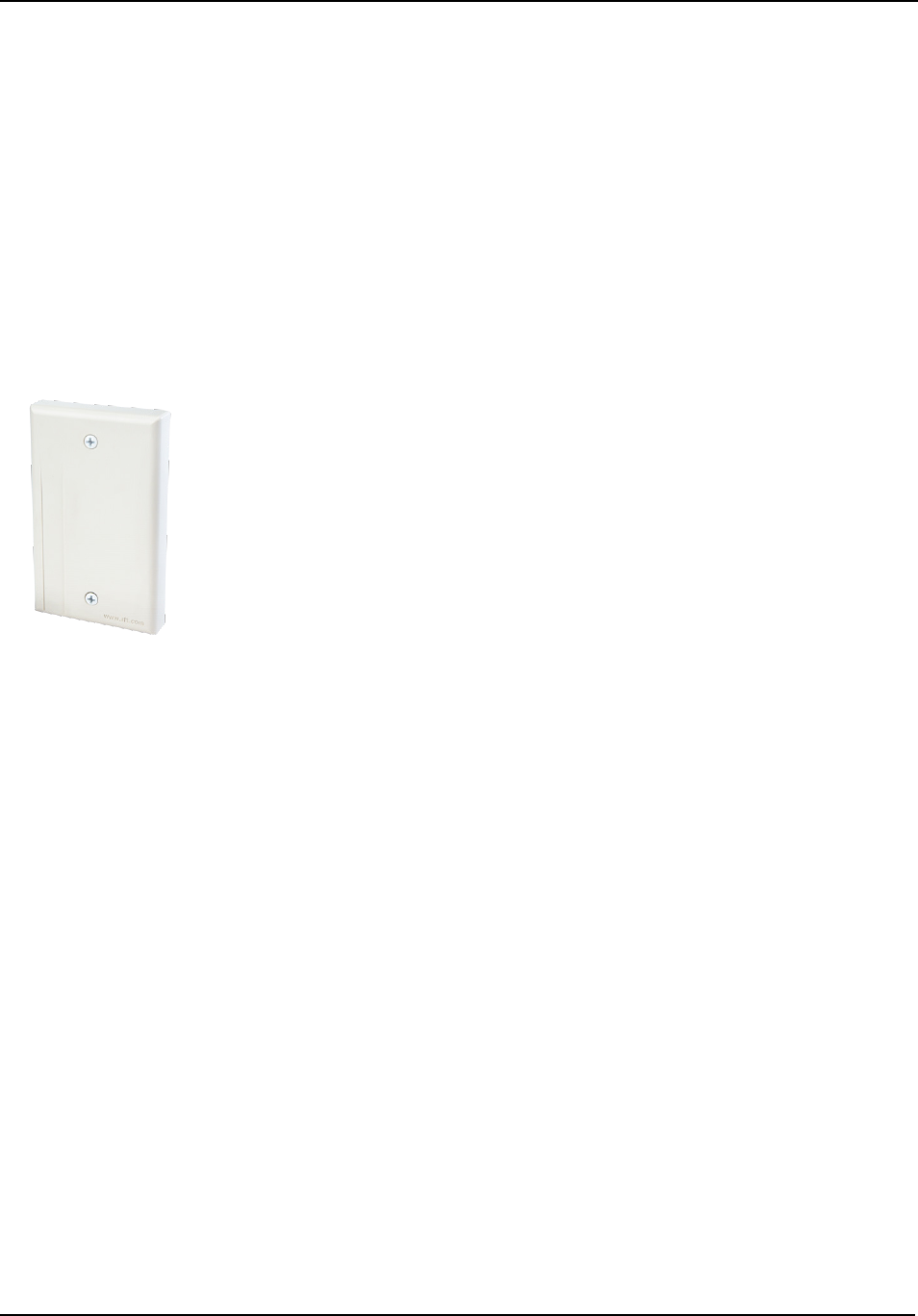
Router
Routers receive signals from transceivers and re-transmit them to the
Gateway. There are two models of Routers, one with an internal antenna
and one with an external antenna for greater range. Routers can be
supervised; a routine signal is sent from each Router and if the signal is
not received by the system, a Device Fault event is generated in the
Event List at the computer.
Routers are powered by a plug-in power supply or central power supply. A
backup battery is also included in the Router enclosure. Routers can be
placed on either the wall or on the ceiling. If mounting to the ceiling, the
issue of bleeding through to the floor above must be considered. Other
factors that affect the placement of Routers are the availability of a power
source and sufficient coverage for the supervision of transceivers.
The Router has four (4) single-color LED lights; two green and two red.
For more information on LED lights and LED sequence refer to the LED
Sequence section
RF Fail-Good: The two sets of lights furthest from the Reset Button
indicate transceiver device communication status. These set of lights flash
briefly (once) every check-in (30 seconds by default), when a tamper
alarm is triggered or cleared, and when a data is forwarded.
Green indicates communication is good and data is forwarded
OK to the next Router.
Red indicates communication failure and data is NOT forwarded
to the next Router.
Serial Fail-Good: The two sets of lights closest to the Reset Button
indicate RS232 communication status with the Central Server. These set
of lights flash briefly (once) when data is transmitted via an external
RS232 device (i.e. Quick Look™) to the Central Server.
Green indicates that the external RS232 device loopback is
detected.
Red indicates that the external RS232 device loopback is not
detected.

Chapter 1 – Installing Hardware Components
Quick Response Premiere Hardware Installation Guide Page 19 of 77
0510-1099-I
NOTE: A configuration map or floor plan of the facility is pre-determined
with most Quick Response Premiere Wireless Call Systems. Please rely
on the configuration map or floor plan in conjunction with the information
provided below to determine Router placement.
To determine placement of routers:
1. The first Router's location is in the proximity of the Gateway as
specified on the floor plan. Using a Pendant that is in Survey Mode,
walk a distance from the Gateway until the light on the Pendant starts
blinking red. This indicates that the Router is out of range of the
Gateway.
2. Walk back into range.
3. Mount Router within range of the Gateway and near a 110 VAC wall
outlet or at the termination point from the central power supply.
Repeat steps 1 and 2 to mount subsequent Routers.
NOTE: If using a 9V power supply, wiring from the power supply can
be routed inside the wall or (if preferred) mount the raceway for
containing and concealing the wires leading from the underside of the
Router down to the 110 VAC wall outlet.
4. For wall placement, the Router should not be located over a stud and
should be at a distance of one foot from the bottom of the enclosure
to the ceiling.
5. For ceiling placement, the Router should mounted down the center of
the hallway or centered in a room. Its orientation can be parallel or
perpendicular to the walls of the hallway. For optimal location, mount
Router in the center of the ceiling tile.
6. Using the rear plate of the Router as a template, place it level against
the intended mounting surface and mark the location of the two
mounting holes. If the wiring from the wall outlet power supply or
central power supply exits from the intended mounting surface then
locate the lower right corner of the rear plate (corner is cut out) over
the exit hole.
7. Center punch each hole and drill in two nylon wall anchors (included).
If the Router is located on a concrete mounting surface then you must
use the wall anchors designed for use with concrete (not included). If
the Router is to be installed on drop ceiling tiles use the threaded
drywall anchor taking care to not damage ceiling tile during installation
process.
8. Once the wiring has been run to the location of the Router attach the
power supply wires to the terminal block in the corner of the Router. If
using a central power supply up to seven (7) Routers may be daisy
chained by terminating the next Router to the second terminal block.
The minimum field wire size to be employed shall be 18 AWG (0.36
mm2).
9. Insure that the wires are pulled tight through the wire tie wrap and cut
excess.
10. Make certain that the Router's ON/Off switch is in the ON position.
After the ON/Off switch is turned to the ON position, the LED’s at the
bottom of the device should flicker. If they do not flicker then turn the
switch to the OFF position and then turn it back ON.
11. Place the rear plate of the Router into the recess on the back of the
Router enclosure.
Chapter 1 – Installing Hardware Components
Page 20 of 77 Quick Response Premiere Hardware Installation Guide
0510-1099-I
12. Place the Router over the wall anchors in alignment with the holes in
the enclosure and insert two screws (included). Verify Router is firmly
secured to the intended mounting surface to prevent the device from
falling.
13. For extended range Routers make certain that the external antenna
points over the top edge of the enclosure. Any other orientation will
reduce device performance.
14. If raceway is being used now is the time to apply it.
15. If the power is supplied by a wall outlet power supply, then plug in the
power supply.
16. If the power supply has a mounting tab, secure it to the outlet using
the screw provided.
17. Repeat the above steps for the remaining Routers.
NOTE: When configuring a multi-story facility the Routers should be
placed directly above one another as much as possible to provide
accurate location even in non-location required facilities.
To test the Routers:
1. For each router use a pendant that is in Survey Mode to test
reception. Walk to the far reaches of adjacent rooms and covered
area to ensure that acceptable coverage is achieved.
2. For Quick Look displays, verify location data and alarm information
appears on the display when an alarm is generated.
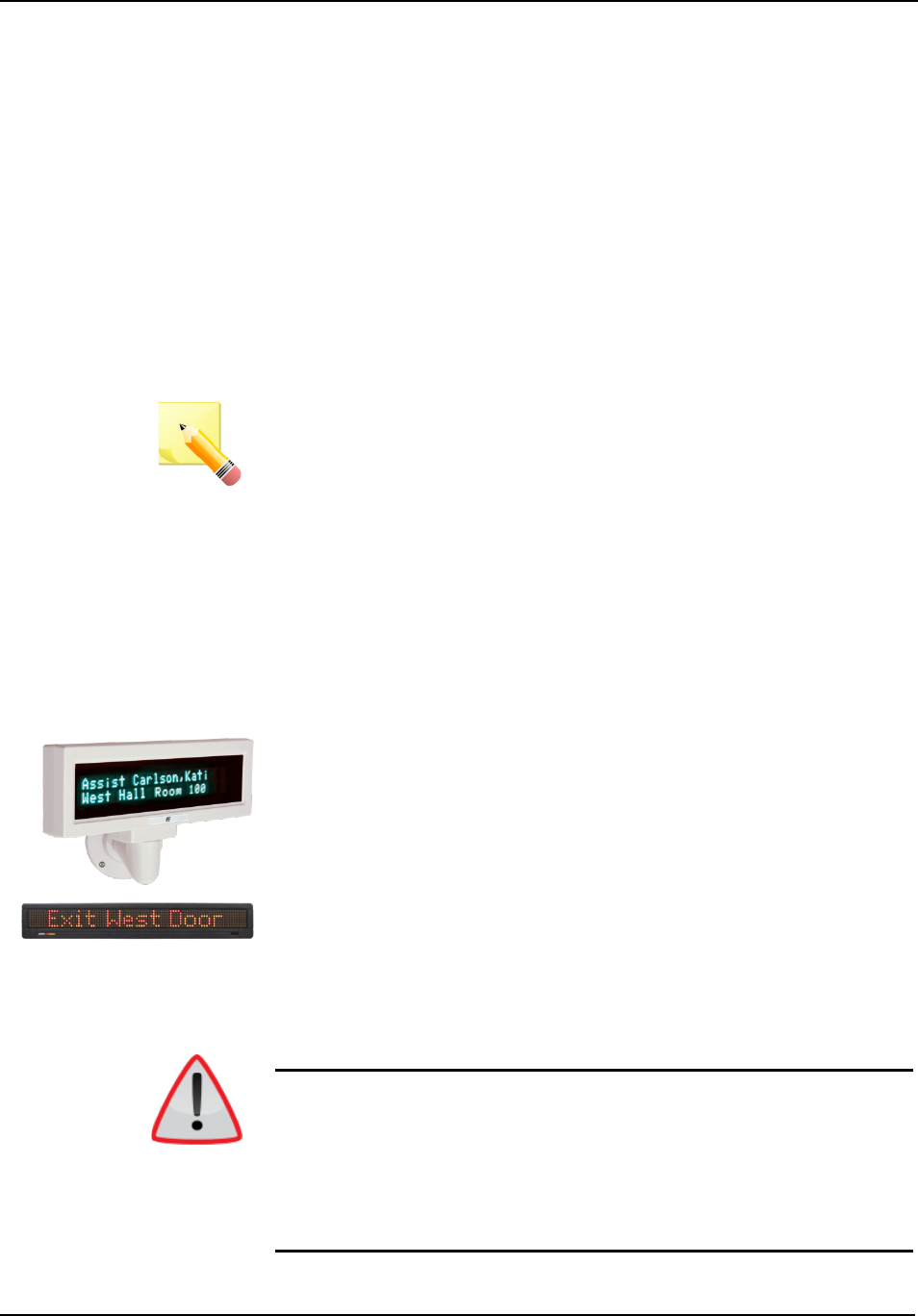
Quick Look
A Quick Response Premiere Router can be connected to a wireless Quick
Look Display or High Visibility Display so that when an alarm is sent from
the Server to the Router, the wireless display shows the type of alarm,
location data and transceiver number. As new alarms occur, they appear
immediately; the display then begins scrolling through each active alarm.
The Quick Look Display also acts as an integral part of the back-up
reflector mode. This reflector mode functionally allows the Quick
Response Premiere network to take over the responsibility of distributing
alarm information (transceiver number only) to the Quick Look Display in
the event of an inoperable Server. In reflector mode it will display device
names and the nearest Router that received the alarm.
Quick Looks are supervised; a routine signal is sent from each Quick Look
Display and if the signal is not received by the system, a Device Fault
event is generated in the Event List at the computer.
WARNING: Quick Look Displays should not be added to multiple units.
Since Routers are used to determine location, inaccurate location data
could result.
The location data displayed depends on the configuration. If a
Gateway/Router is assigned to a room, the Quick Look displays the room
and unit data. If the Router/Gateway is assigned only to a unit and not
individual rooms, the nearest location data is displayed.
Chapter 1 – Installing Hardware Components
Quick Response Premiere Hardware Installation Guide Page 21 of 77
0510-1099-I
WARNING: It is crucial that the following steps be carried out in the order
listed. If the display is not powered and connected properly to the Router
when the Router is initially powered on, the display will not function.
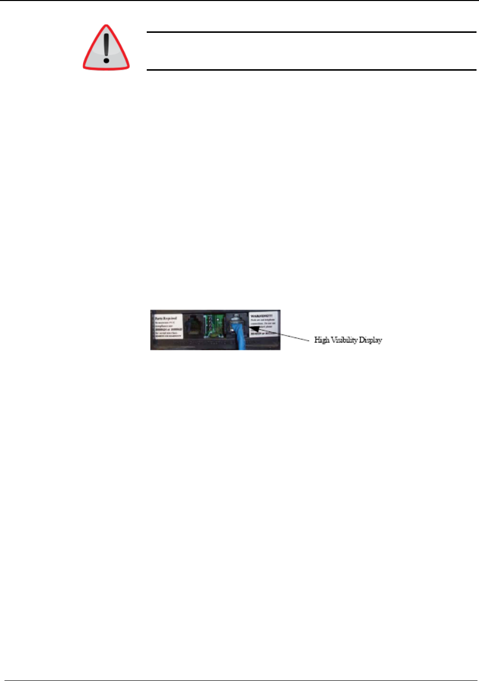
To install the Quick Look display:
1. Mount the High Visibility Display in the desired location, near a 110
VAC wall outlet. Use the following steps for mounting the High
Visibility Display as a wall-mount or counter-mount display.
2. Attach mounting brackets 281/8 inches apart, in desired location. If
mounting in drywall, screw anchors must be used.
3. Once brackets are in place, put the display between the two brackets
and secure it to the brackets with the two thumb screws provided.
4. To maximize visibility, first adjust the tilt of the display and then tighten
the thumb screws.
5. Plug the 7 VAC 4.8A power supply into the High Visibility Display and
connect it to wall power outlet.
6. Connect the Router to the High Visibility Display.
7. Plug the RJ-45 end of the 10-foot connector cable into the RJ-45 port
on the back of the High Visibility Display.
8. Plug the RS-232 end of the 10-foot connector cable into the RS-232
terminal on the lower right hand corner of the Router.
9. Wire the Router for power via the power terminal in the Router, noting
the correct polarity.
10. Mount the Router within 10-feet of the High Visibility Display, near a
110 VAC wall outlet.
11. Connect the Router’s power supply to a 110 VAC wall power outlet.
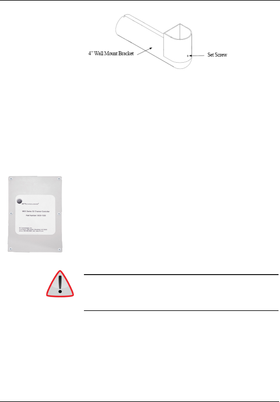
To mount the Quick Look Display:
1. Feed the wire attached to the head assembly of the Quick Look
Display through the un-notched end of the 4” wall-mount bracket.
2. Slide the head assembly onto the end of the 4” wall-mount bracket.
3. Secure it in place by tightening the set screw located on the end of
the post or bracket.
4. Align the notches in the Quick Look base with the notches in the 4”
wall-mount bracket and hold together.
5. Feed the retaining nut over the wires leading out of the bottom of the
base.
6. Tighten the retaining nut.
7. Be careful not to strip or damage the mounting base assembly.
8. Screw the base into the wall using the four screws provided.
Chapter 1 – Installing Hardware Components
Page 22 of 77 Quick Response Premiere Hardware Installation Guide
0510-1099-I
9. Wire the Router for power via the power terminal in the Router, noting
the correct polarity.
10. Make certain that the Router’s ON/OFF switch is in the ON position.
After the ON/Off switch is turned to the ON position, the LED’s at the
bottom of the device should flicker. If they do not flicker then turn the
switch to the OFF position and then turn it back ON.
11. Mount the Router within 4-feet of the Quick Look Display, near a 110
VAC wall outlet.
12. Connect the Router’s power supply to a 110 VAC wall power outlet.
32 Channel
Controller
The 32 Channel Controller consists of a Quick Response Premiere
Router, a 32 Channel Controller relay board and up to 16 bi-color Dome
Lights.
The 32 Channel Controllers are supervised; a routine signal is sent from
each Quick Response Premiere Router and if the signal is not received by
the system, a Device Fault event is generated in the Event List at the
computer.
Central Power Supply (CPS)
The Central Power Supply is used to connect the 32 Channel Controller
and Dome Lights to a single power source. The Central Power Supply
eliminates the need to run 120VAC to each detection zone. Note that the
Router is powered by the 32 Channel Controller.
Refer to the Class II Central Power Supply Installation Guide (0510-1036)
for detailed information on installing the Central Power Supply.
WARNING: It is crucial that the following steps be carried out in the order
listed. If the 32 Channel Controller is not powered and connected properly
to the Router when the router is initially powered on, the controller will not
function. The 32 Channel Controller must be set to its assigned channel
prior to assigning devices.
Chapter 1 – Installing Hardware Components
Quick Response Premiere Hardware Installation Guide Page 23 of 77
0510-1099-I
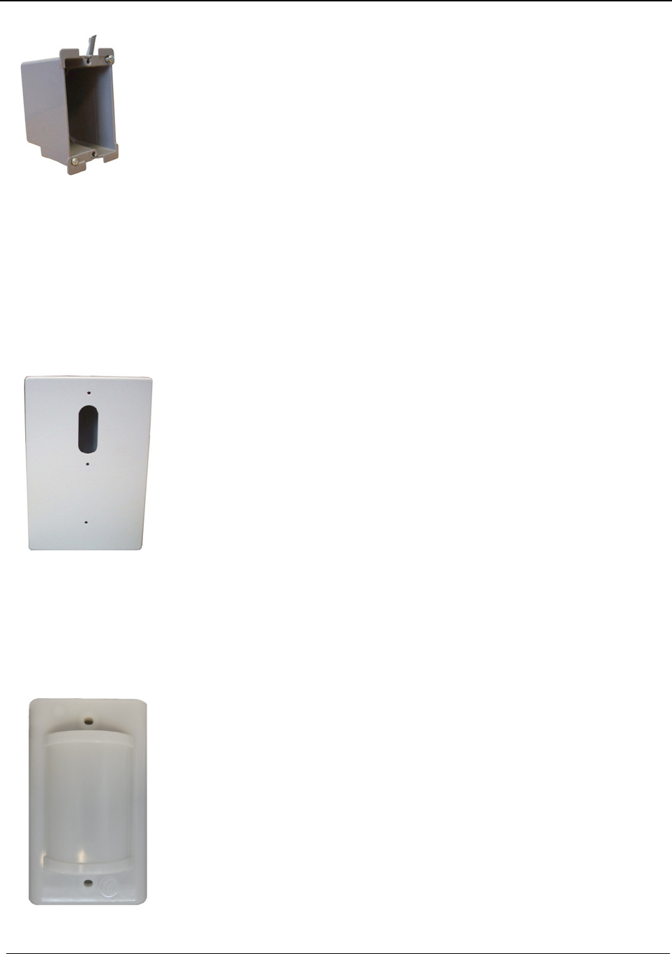
To flush mount the single gang enclosure for the 32 Channel
Controller:
1. Locate a mounting site for the 32 Channel Controller, preferably on a
wall that a single gang electrical box can be mounted.
2. Hold the single gang mounting enclosure against the wall. Use
standard installation practices to position and level the enclosure then
mark out the area around the enclosure.
3. Using a drywall hole saw, cut out the area where the enclosure is to
be placed. Be sure that the area is only as big as the enclosure or the
clamps will not attach securely to the wall.
4. Run the wires from the CPS and Dome Lights to the hole.
5. After routing the wires through the single gang electrical box place the
clamps flat against the box and insert the unit into the wall.
6. Tighten the clamps using the provided screws.
7. Where necessary, mount the enclosure to a wall stud by screwing or
nailing the enclosure to the side of the stud through the two provided
holes.
To mount the 32 Channel Controller enclosure:
1. Using a Phillips screwdriver, remove the six screws that hold the face
plate to the enclosure.
2. Remove the faceplate.
3. Thread wires through the hole in the back of the enclosure.
4. Secure the enclosure to the single gang mounting enclosure with two
screws (the third hole on the enclosure is for extra mounting security).
5. Terminate the wires from the CPS and Dome Lights per the Wiring
Diagram.
6. Route the Router to the 32 Channel Controller Cable Harness from
inside the 32 Channel Controller to just outside the enclosure.
7. Connect the Router cable harness. At this point do not power up
Router and allow it hang free. It will be mounted to the wall following
system power up.
Dome Lights
Dome Lights are mounted in the corridor above or beside the door of an
associated room. The red light should be mounted up. Location should
provide for unobstructed visibility of the Dome Light in both directions.
Dome Lights can either be flush mounted or surface mounted based on
wall construction and wire routing. When flush mounting, the wiring can be
routed through a 3/4" hole in the wall. In this case the Dome Light will be
directly mounted to the wall.
Dome Light includes two indicator lights: a white indicator light for low
priority alarms and a red indicator light for high priority alarms.
Emergency Calls: Emergency calls are indicated by steady
illumination of the red Dome Light associated with the zone or area
from which an emergency call has been placed.
Normal Calls: Normal calls are indicated by steady illumination of the
white Dome Light associated with the zone or area from which a
normal call has been placed.
Chapter 1 – Installing Hardware Components
Page 24 of 77 Quick Response Premiere Hardware Installation Guide
0510-1099-I
Concurrent Emergency and Normal Calls: If emergency and
normal calls are placed at the same time, the red light connected to
the emergency station from which a call was placed will illuminate at
the same time as the white light associated with the normal call.
To surface mount the Dome Light:
1. Hold the base of the surface mount enclosure against the wall at the
desired mounting height with the sharpened side parallel and square
to the floor.
2. Mark the location of the two mounting holes.
3. Drill holes where the marks were made. If the drilled holes do not hit a
stud wall you must use wall anchors (not included).
4. Line up the holes on the base of the enclosure with the newly drilled
holes.
5. Mount the base of the enclosure to the wall using two drywall screws.
6. Snap the surface mount enclosure onto the base previously attached
to the wall.
7. Terminate the wires per the instructions following this section.
8. Once the Dome Light has been wired route any excess wiring back
into the enclosure as the Dome Light is placed over it.
9. Secure the Dome Light to the surface
To flush mount the Dome Light:
1. Terminate the wiring per the instructions following this section.
2. Route any excess wiring back into the wall, as the Dome Light is
placed over the hole and against the wall.
3. Once the Dome Light is square to the floor, secure it to the wall with
the two screws provided.
4. If screws do not hit a stud, then drywall anchors (not included) will be
necessary.
NOTE: By default, this assembly is hardwired to normally closed.

Chapter 1 – Installing Hardware Components
Quick Response Premiere Hardware Installation Guide Page 25 of 77
0510-1099-I
To wire power to Dome Lights:
1. Run wiring conduit from Dome Light to Dome Light and terminate at
the Central Power Supply. The current requirement for the Dome
Light is 50mA. Each circuit should be limited to 8 or fewer Dome
Lights. Use 16 AWG 2-conductor cable to connect the Dome Light
power terminals to the Central Power Supply.
2. Terminate the wires per the Wiring Diagram.
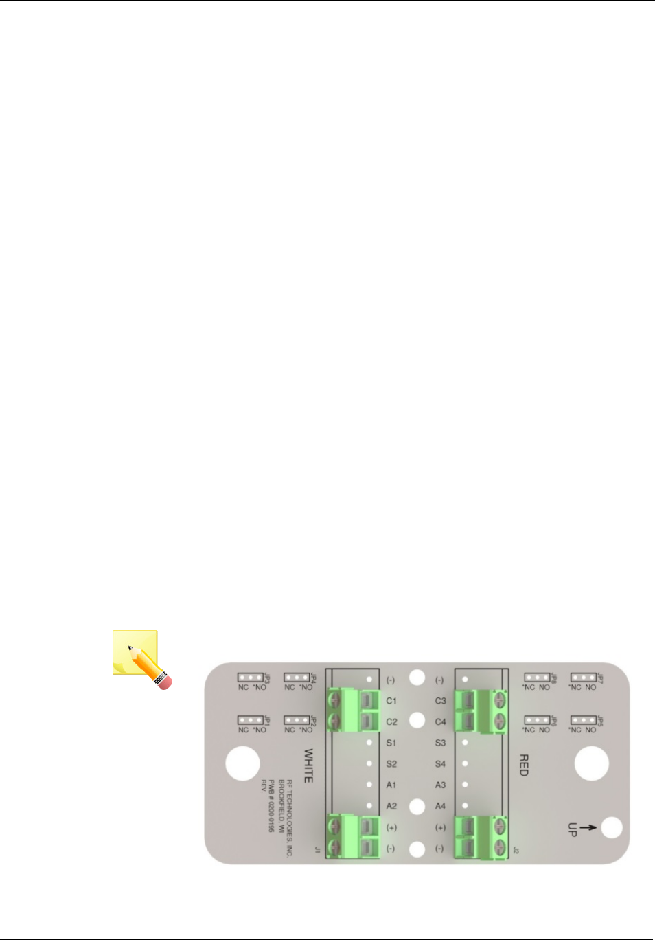
To wire Dome Lights to the 32 Channel Controller:
1. Run a 22 AWG 4-conductor or 8-conductor cable to connect one of
the Dome Light circuit’s terminals to the 32 Channel Controller.
2. Connect one pair of the cable conductors from the Dome Light’s
C1(+) and C2 terminals to one of the 32 Channel Controller’s relay
output circuits.
Circuits 01 and 02 have both Normally Open (NO) and Normally
Closed (NC) contacts
o The N/C contacts are open during normal operation
o The N/O contacts are closed during normal operation
NOTE: The N/O contacts are in the closed state so in the event a
wire is cut, it will act as supervision and illuminate the dome light.
Circuits 03 thru 32 have Normally Open (NO) contacts.
o These circuits are closed during normal operation. In the
event of an alarm state, these circuits then change to the
open state.
NOTE: The contacts are in the closed state so in the event a wire is
cut, it will act as supervision and illuminate the dome light.
3. Repeat the above step for the second Dome Light circuit (C3 and C4)
using either another 4-conductor cable or the 3rd and 4th pairs of the
8-conductor cable, if used.
4. Use the tie wrap provided to wrap around the terminated wires and
tightly attach it to the holes in the 32 Channel Controller circuit board.
5. Once the Dome Light has been wired, slip the wires back into the wall
until the two support posts on the circuit board rest against the
mounting surface.
32 Channel Controller System Power Up:
1. Make certain that the power switch on the Router is OFF.
2. Turn the power switch on the 32 Channel Controller to OFF.
3. Turn the power switch on the 32 Channel Controller to ON.
4. Turn the power switch on the Router to ON. After the ON/OFF switch
is turned to the ON position the LED’s at the bottom of the device
should flicker. If they don’t flicker then turn the switch to the OFF
position and then turn it back ON.
5. Secure faceplate of the 32 Channel Controller with six screws.
6. Proceed to configuring the 32 Channel Controller.
Chapter 1 – Installing Hardware Components
Page 26 of 77 Quick Response Premiere Hardware Installation Guide
0510-1099-I
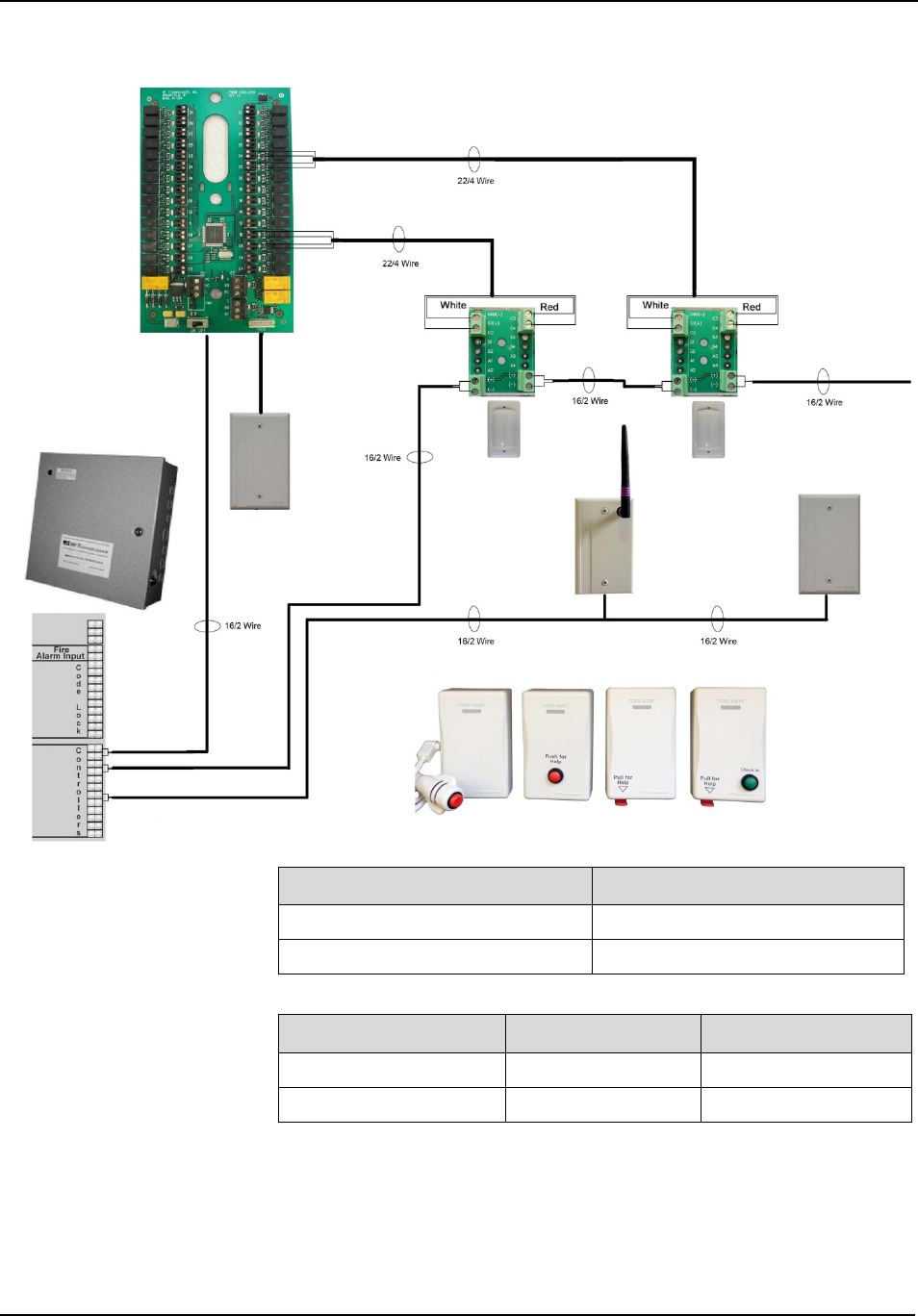
Wiring Diagram
Central Power Supply
Red or White Dome Light
+ +
- -
Central Power Supply
White Dome Light
Red Dome Light
Zones 1-32 Contact 1 C1 C3
Zones 1-32 Contact 2 C2 C4

Chapter 1 – Installing Hardware Components
Quick Response Premiere Hardware Installation Guide Page 27 of 77
0510-1099-I
Power Cable
Run Lengths
This section contains information on maximum power cable run lengths
for installation of daisy-chained Quick Response Premiere Wireless
Routers/Gateways.
Powered by CPS
# Routers/Gateways
CPS - 16/2 AWG
CPS – 18/2 AWG
8 390’ 245’
7 450’ 280’
6 525’ 325’
5 630’ 390’
4 785’ 490’
3 1050’ 650’
2 1575’ 980’
1 3150’ 1960’
Powered by Wall Outlet Power Supply
# Routers/Gateways 12V @ 1.5A
18/2 AWG
9.0V @ 200mA
22/2 AWG
7 140’ N/A
6 160’ N/A
5 200’ N/A
4 250’ N/A
3 330’ N/A
2 500’ N/A
1 1000’ 125’
32 Channel
Controller
Configuration
When each device installed in your facility has been added to the software
database, units must be defined and added. A Unit represents a protected
area in your facility that will be monitored as a unit. All devices associated
with a 32 Channel Controller must be in the same unit. Refer to the
applicable Software Administrator Guide.
To configure 32 Channel Controller:
All devices recognized by the system are listed in the Configuration
Device window. Once the 32 Channel Controller has been installed and
properly wired, the affiliated Router must be configured in the system.
1. Go to the Configuration home page
2. Select Devices
3. The Configuration Devices window opens
Chapter 1 – Installing Hardware Components
Page 28 of 77 Quick Response Premiere Hardware Installation Guide
0510-1099-I
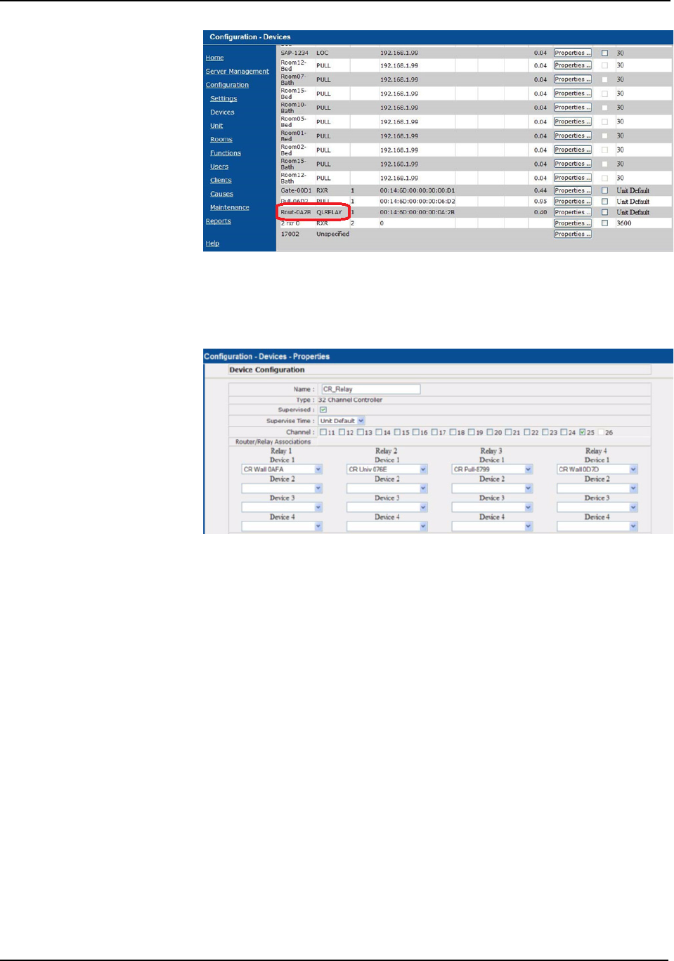
4. Click the Properties box next to the device you wish to update. In this
example the 32 Channel Controller type is displayed as: QLRELAY
5. The Configuration Devices Properties window opens.
Name: Enter the 32 Channel Controller name.
Supervised: Select this check box if you wish to have the
device supervised.
Supervised Time: Select the amount of time, from the drop-
down list, that the system should wait before it initiates a Device
Fault alarm. The Unit Default time is the Transmitter Supervise
Time set during Unit Properties configuration.
Type: Device type is automatically filled in
Channel: Choose the channel assigned to the Gateway/Router
(default 25). Channel selection is site specific and dependent on
the sites environmental issues.
Router/Relay Association: Select the devices associated with
a relay. There are 32 relays; each relay is capable of monitoring
four devices. The Dome Light is triggered if any of the devices
associated with that relay goes in alarm. Devices selected must
be from the same unit as the 32 Channel Controller.
6. Click Save to save your changes
Chapter 1 – Installing Hardware Components
Quick Response Premiere Hardware Installation Guide Page 29 of 77
0510-1099-I
To test the 32 Channel Controller:
When an alarm is sent from the Server to the Router, the 32 Channel
Controller acts as a relay switch and turns on the Dome Light mounted
outside the patient’s room. Once the 32 Channel Controller /Dome Light
setup has been configured and wired properly, you must test its operation.
1. Position yourself where you can see the Dome Light.
2. Have someone activate a transceiver device.
3. If the 32 Channel Controller and Dome Light have been wired
correctly, the Dome Light will illuminate and an Alarm event will be
listed on the Event List at the Central Server.
4. Reset the transceiver device and follow step 1– 3 to test all 32
Channel Controller/Dome Light setups.
Channels
The Gateway and Router default to channel 25. In a facility with a single
Gateway, it is recommended to leave the Gateway and Routers on
channel 25.
In some instances, it may be necessary to install an additional Gateway to
support additional Routers. Once the first installation of Gateway/Routers
is complete and configured into the system, you must change the channel
before installing the second set.
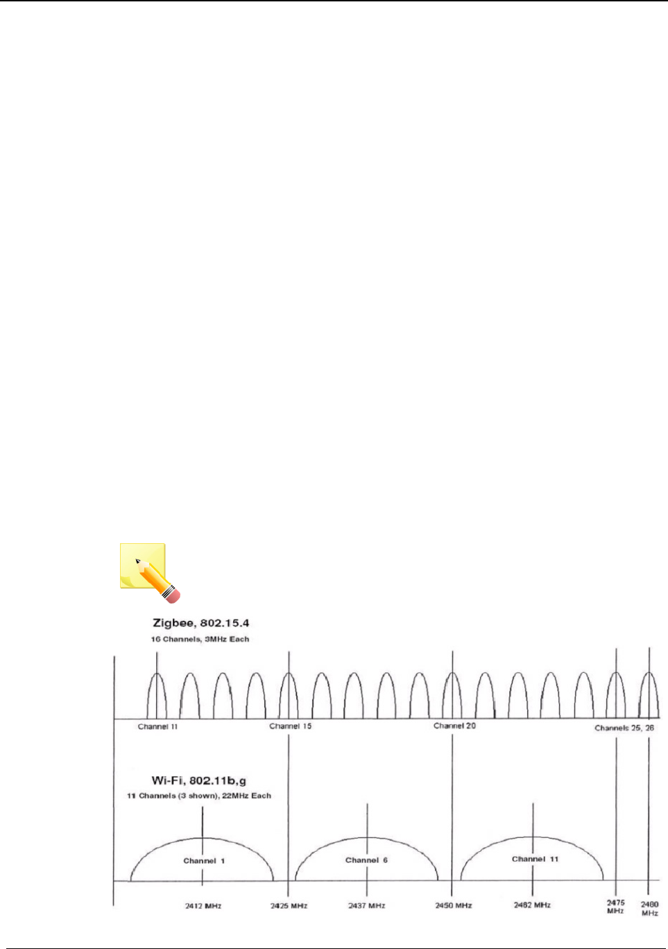
Channel selection will be site specific and dependent on the sites
environmental issues. Environmental issues include WiFi, 2.4 cordless
phones, microwave ovens, and architecture (multiple Gateways). There
are 16 ZigBee channels in the 2.4 spectrums numbered 11 to 26 (1–9 are
in the 900MHz spectrum). Channel 26 is unusable as the power output is
limited to half of the other channels due to its proximity to the edge of the
2.4. spectrums, and is configured “off” in our systems.
NOTE: Channel 25 is the default for all our devices. The preferred
channels are 11, 15, 20, and 25.
Chapter 1 – Installing Hardware Components
Page 30 of 77 Quick Response Premiere Hardware Installation Guide
0510-1099-I
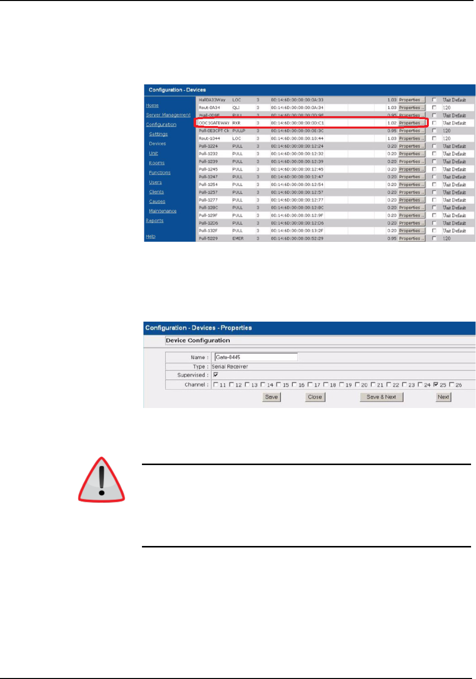
To change gateway and router channels:
1. Go to the Configuration home page
2. Select Devices
3. The Configuration Devices window opens
4. Click the Properties box next to the Gateway.
5. Deselect the default channel (25) and select the new channel.
Selecting a new channel for the Gateway will also change the channel
for all associated Routers.
6. Click Save and then close the window.
WARNING: WAIT! You must wait at least 60 seconds before using the
Scan Devices function.
Once the channel for the Gateway and Routers has been changed, you
must Scan Devices on that comport to establish the change in the system.
The Gateway will not use the new channel until the Scan Devices function
is complete.
Router Depth
It is important to install Routers efficiently as to minimize the number of
hops to the Gateway while still providing coverage at the furthest point
from the Gateway. The Router Depth option allows you to adjust Router
Depth by staggering 5-second Router resets by one, two, three or four
minutes. Each Router has an association limit of 6 Routers; the hop limit
for each Router is 4.
Chapter 1 – Installing Hardware Components
Quick Response Premiere Hardware Installation Guide Page 31 of 77
0510-1099-I
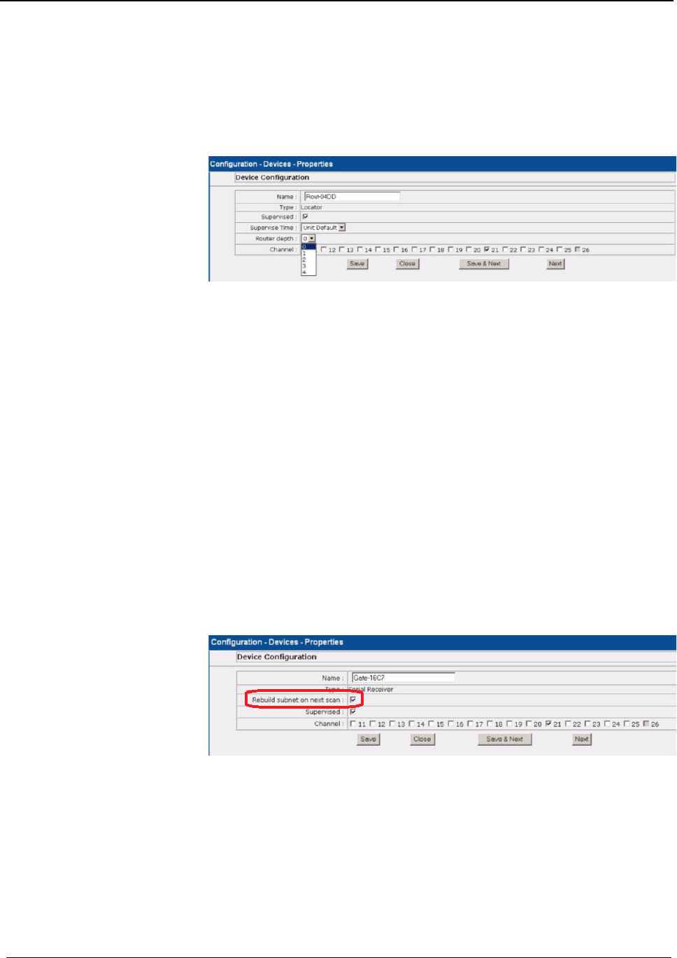
To select the Router Depth:
1. Go to the Configuration home page
2. Select Devices
3. The Configuration devices window opens
4. Click the Properties box next to the Route.
5. The Configuration Device Properties window opens.
6. Select the Router depth from the drop-down list
7. Click Save and the close the window.
8. Once the Router Depth is selected, you must rebuild the subnet on
scanned devices
Rebuild Subnet on
Scanned Devices
To rebuild the subnet on scanned devices:
1. Go to the Configuration home page
2. Select Administrative Functions
3. Select Configuration
4. All devices recognized by the system are listed in the Configuration
Device window.
5. Select Devices
6. The Configuration Devices window opens
7. Click the Properties box next to the Gateway
8. The Configuration Device Properties window opens
9. Click the checkbox next to Rebuild subnet on next scan
10. Click Save and then close the window.
11. You must execute the Scan command on that Gateway’s comport to
begin.
Chapter 1 – Installing Hardware Components
Page 32 of 77 Quick Response Premiere Hardware Installation Guide
0510-1099-I
WARNING: Rebuilding the subnet should only be done when end devices
are not present during installation. During the Rebuild, the system will be
down for up to 10 minutes.
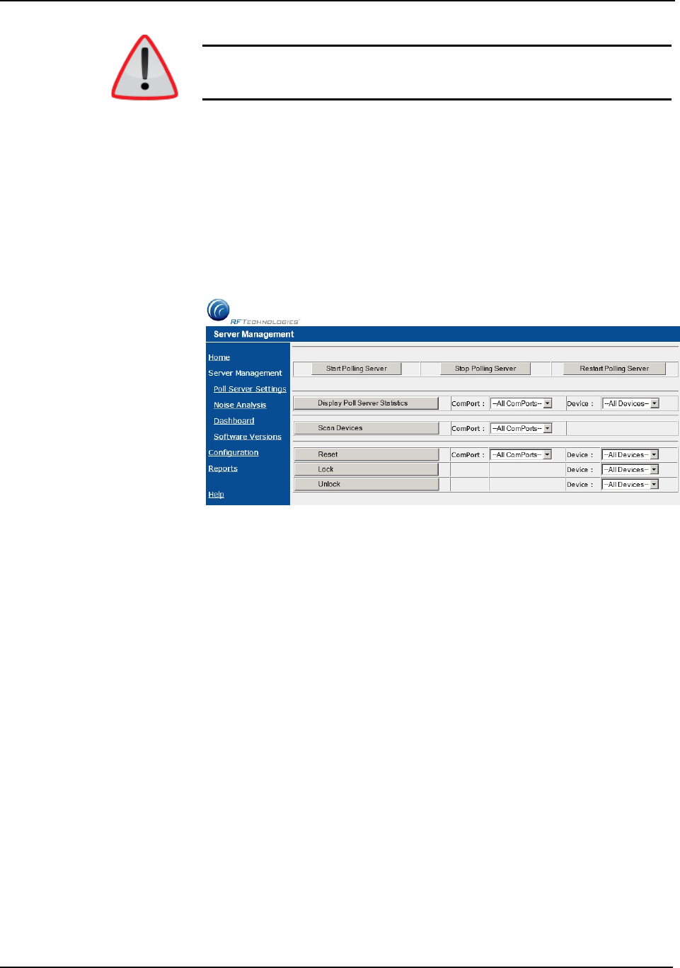
Scan Devices To scan devices:
1. Go to the Configuration home page
2. Select Administrative Functions
3. Select Configuration
4. The System Management Home page opens.
5. Select Server Management
6. The Configuration Server Management home page opens.
7. Next to the Scan Devices button, select the ComPort assigned to the
Gateway/Router from the ComPort pull-down.
8. Click Scan Devices, a Scan Status window opens verifying the
successful completion of the scan.
9. Click Close to close the Scan Status window and return to the Server
Management home page.
10. Open the Dashboard and verify the Gateway and each of the Routers
are communicating.
11. Install the next Gateway and Router
Chapter 1 – Installing Hardware Components
Quick Response Premiere Hardware Installation Guide Page 33 of 77
0510-1099-I
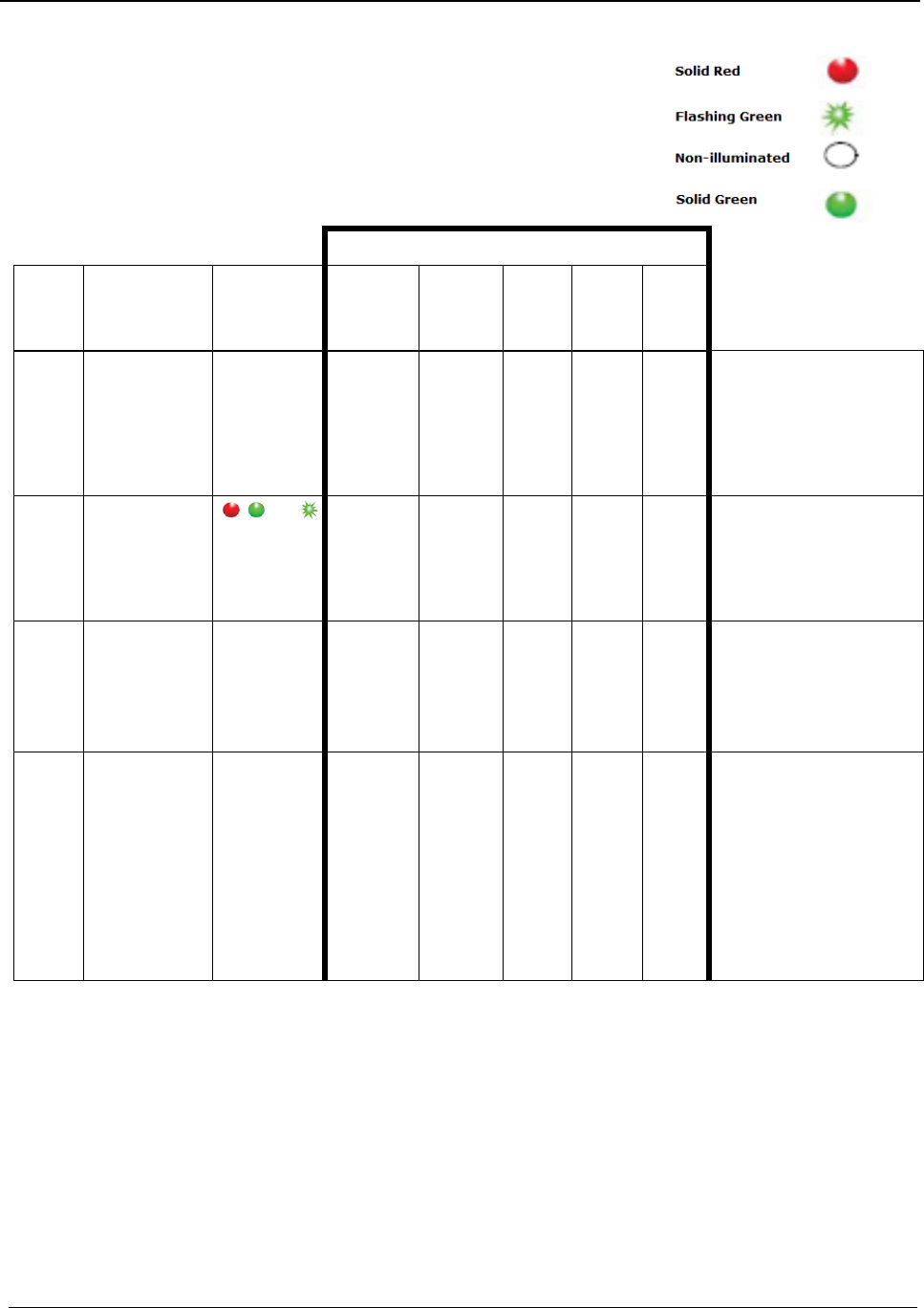
Gateway /
Router Reset
Button
The Router has four types of reset.
Respectively, the Gateway supports the
first three. By using the reset button on the
bottom edge of the Router/Gateway you
can perform the resets described in the
chart below.
Action Upon Release of Reset Button
Reset
Type
To Execute Press
and Hold Reset
Button
Release Reset
Button When
LED Illuminates
Associated
(child)
End-
devices
Associated
(child)
Routers
Routing
Table
Device
Name
Channel
LED Sequence After Release of
Reset Button
1-second
Hold until 1 LED
comes on solid
(about 1 second)
No change
No change
Clear
No
change
Same
1.
2.
3.
4.
L1, L2, L3, L4
(sequentially)
All LEDs on
Green LEDs flash
Single green flash if
communication is successful
5-second
Hold until 2 LED
comes on solid
(about 5 seconds)
Clear
No change1
Clear
No
change
Same
1.
2.
3.
4.
L1, L2, L3, L4 (sequentially)
All LEDs on
Green LEDs flash
Single green flash if
communication is successful
10-second
Hold until 3 LED
comes on solid
(about 10 seconds)
Clear
Clear
Clear
Default2
25
1.
2.
3.
4.
L1, L2, L3, L4 (sequentially)
All LEDs on
Green LEDs flash
Single green flash if
communication is successful
15-second
Hold until 4 LED
comes on solid
(about 15 seconds)
Clear
Clear
Clear
Default2
Scan3
1.
2.
3.
4.
5.
6.
L1, L2, L3, L4 (sequentially)
All LEDs on
No LED activity for 30
seconds while channels are
scanned
Green LEDs flash
Blink red RF 30 seconds
Single green LED flash and red
RF LED flashes for 15 seconds
If a Router/Gateway does not have child Routers (at the end of a
branch in the tree structure), a 5-second reset will cause the
Router/Gateway to leave the network, and then rejoin the network. On
the Router, this is indicated by observing the L2 flash off and back on
after 5-seconds.
A 10-second or 15-second reset will cause a Router/Gateway name
to revert to factory default; Rout-xxxx/Gatexxxx, where xxxx are the
last 4 characters of the Router/Gateway MAC ID.
The Router will scan all channels and will join the first channel that
replied with the highest RSSI (and stay on that channel indefinitely
unless another 15-second reset is done).
Chapter 1 – Installing Hardware Components
Page 34 of 77 Quick Response Premiere Hardware Installation Guide
0510-1099-I
LED Sequence
Power Up Sequence LED Sequence Explanation
L1, L2, L3, L4 (sequentially) Device executing normal firmware
All LEDs On (not maintained) Device executing normal firmware
NOTE: If power up sequence does not occur and the green light is
blinking every second, than the device is in manufacturer’s mode.
Display Sequence LED Sequence Explanation
Dual Green LED Flash (10
times)
Device is attempting to identify a
Router/Gateway parent.
Single Green LED Flash (L2) Successfully joined with and checked
in with identified parent.
Single Red LED Flash (L1) No response from identified parent.
Repeating (dim) Red LED
Flash (L3)
Device operating normally, flashes
once per second (heart beat
indicator).
Dual Green LED Flash (one
time)
Router/Gateway Successfully
forwarded packet from a child to the
Central Server or display.
Single Green LED Flash (L4) Gateway received the check in
message sent by Server every 15
seconds.
L3 and L4 Solid Illumination Battery switch turned off or battery
fully discharged and requiring the
Quick Response Premiere Router
Battery Recharger procedure .
Troubleshooting
The Quick Response Premiere network of devices is partially capable of
self-maintenance in the event a device fails. The system software has four
data communications to aid in the maintenance of the network.
Reset: Force individual Routers, all Routers on a single comport
or all Routers on all comports to reset
Scan: Forces the Gateway and all its Routers to change channel
Configure: Individual device (name, supervision rate, channel
mask)
Delete: Remove individual devices from Router tables

Chapter 1 – Installing Hardware Components
Quick Response Premiere Hardware Installation Guide Page 35 of 77
0510-1099-I
End Device
Failure
When a single, limited function end device (i.e. Pull Cord, Universal) fails,
the following procedure will remove it from the short address table and
allow replacement.
To replace a failed end device:
1. Unpower and physically remove the failed device.
2. Delete the device from the Configuration >>Devices window in the
software. This results in a broadcast command to the Gateway to
remove the MAC short address from the Router table it was joined to.
3. With the replacement device within range of the Router, remove the
battery tab to activate the device. The replacement device will
automatically search all channels to find a “full function” device to join.
4. Physically install the replacement device.
5. Alarm and then Reset the device. The system recognizes the device
when it goes into alarm and places it into the Device List for
configuration.
6. Configure the replacement device in the software using the same
device name as the failed device previously deleted.
7. If necessary, configure the replacement device into a Unit.
8. If necessary, configure the replacement device into a Room.
Cloning
In case the router or gateway is still operating but needs to be replaced
due to faulty RF communication, etc, follow the steps outlined in the Quick
Response Premiere Router/Coordinator Cloning Guide (P/N 0510-0401).
Router Failure
When a full function device (Router) fails, its limited function device (i.e.
Pull Cord, Universal) will fail to communicate and will automatically search
for another Router to associate with for a check-in or alarm.
To replace a failed Router (router has lost all ability to operate):
1. In the software application, click Report on the toolbar and open the
Device Tree Report.
2. Sort the Device Tree Report by Comport and print the report.
3. Find the Router and all of its dependent Routers and make a list of
these Routers (any Routers that contain the defective Router name in
their path).
4. Remove power from each Router noted in step 3.
If AC power is provided by a CPS, turn the CPS output off at
this time (all Routers will report low battery in 5 minutes, but
that’s OK).
If AC power is provided by individual wall transformers,
unplug the wall transformer for each Router
Remove battery power (turn battery slide switch to off position)
for each Router
5. In the software, delete all of the Routers noted in step 3 (check delete
then click save).

Chapter 1 – Installing Hardware Components
Page 36 of 77 Quick Response Premiere Hardware Installation Guide
0510-1099-I
6. Remove battery from each end device that could possibly be within
range of the Routers noted in step 3.
7. Replace the defective Router.
8. Start with just the new Router for the steps below.
9. Apply power to the Router.
Apply battery power (turn battery slide switch to on position) for
this Router. After the ON/Off switch is turned to the ON position,
the LED’s at the bottom of the device should flicker. If they do not
flicker then turn the switch to the OFF position and then turn it
back ON.
If AC power is provided by a CPS, leave the CPS output off for
now.
If AC power is provided by individual wall transformers, plug
in the wall transformer for this Router.
10. Perform a 15-second reset on this Router
11. Wait for a visual indication Router joined the network (dual green
blinks for several seconds).
12. Secure the Router to the wall.
13. Repeat steps 9-11 for all remaining Routers noted in step 3
NOTE: Remaining Routers must be done in the order of shortest path to
longest path based on the tree report from step 2
14. Verify each Router noted in step 3 now appears in the software.
15. If AC power is provided by a CPS, re-enable the CPS output
16. Wait up to the supervision time for a Router and verify none of the
Routers are reporting low battery.
17. Restore each end device from step 6.
With battery still removed, press the tamper switch a few times
(ensures caps are discharged and device performs a proper
power-up reset).
Insert battery.
Verify device light indicator blinks green 3 times. After the ON/Off
switch is turned to the ON position, the LED’s at the bottom of
the device should flicker. If they do not flicker then turn the switch
to the OFF position and then turn it back ON.
Re-mount device.
18. Alarm and clear each end device and verify the PC reports each time
an alarm and clear is sent.
19. Open the Device Tree Report and verify that none of the Routers, or
end devices are reporting an FFFF short address. If the end devices
are, remove their battery, press the tamper switch a few times and
replace the battery. If the Routers are, rebuild the network from that
point out using the above procedure.

Chapter 1 – Installing Hardware Components
Quick Response Premiere Hardware Installation Guide Page 37 of 77
0510-1099-I
Gateway
Failure
When a Gateway fails, its Personal Area Network ID (PAN ID) remains in
the system. Routers and end devices search for connectivity to a single
Gateway’s PAN ID. The PAN ID is based on the Media Access Control
address (MAC address) of the Gateway.
To replace a failed Gateway (gateway has lost all ability to operate):
1. Unpower and physically remove the failed Gateway.
turn off the Gateway
remove the serial cable
remove the external antenna
remove the board from the enclosure
2. Prepare the replacement Gateway.
remove the antenna from the replacement Gateway
remove the board from the enclosure
place the new Gateway in the old enclosure
3. Execute the Gateway Service Set MAC ID Utility.
4. Connect the replacement Gateway to the service technician’s laptop
through the serial port or PortServer.
5. Start the Set MAC ID Utility.
6. Enter the comport of the Gateway and press Enter.
7. Enter the last eight characters of the MAC ID from the original
Gateway and press Enter.
8. Enter the channel number of the original gateway and press Enter.
9. Verify that the programing was successful, then press Q and
disconnect the Gateway from the service technician’s laptop.
10. Perform a 5-second reset on the Gateway.
11. Reattach the external antenna.
12. Connect the power and serial cable on the replacement Gateway.
13. Note the LED sequence on the RS232 status LED.
14. Physically mount the replacement Gateway.
15. Looking at the Dashboard, verify that the Gateway is checking in
every 15 seconds.
16. From the software application, initiate a Reset.
go to the Server Management page
select the ComPort that the new Gateway is connected
click Reset
17. Ensure that all Device Fault events are resolved.
18. Using an RMA form, return the failed Gateway’s circuit board and the
replacement Gateway enclosure to RFT for analysis.

Chapter 1 – Installing Hardware Components
Page 38 of 77 Quick Response Premiere Hardware Installation Guide
0510-1099-I
This page intentionally left blank

Chapter 2 – Installing End Devices
Quick Response Premiere Hardware Installation Guide Page 39 of 77
0510-1099-I
Chapter 2 – Installing End Devices
Introduction
This chapter provides detailed information about installing end
(transceiver) devices and testing the operations of the Quick Response
Premiere Wireless Call System with supported devices.
End devices are devices that transmit and receive alarm data. The Quick
Response Premiere Wireless Call System includes end devices that are
carried by the patient and fixed devices (a stationary device that is
assigned to a room or a unit and is not transported with the patient but
stays in the room or unit to which they are assigned).
The Quick Response Premiere Wireless Call System end devices consist
of the following:
Pull Cord/Emergency Call Station
Pull Cord with Check-In Call Station
Push Button Emergency Call Station
Nurse Call Station
Universal Transceiver
Door/Window Transceiver
Pendant
NOTE: Pull Cords and Universal Transceivers check in every 20 minutes;
Pendants check-in every 100 seconds by default.
NOTE: Any transceiver devices that are to be assigned to a 32 Channel
Controller must be on the same PAN as the 32 Channel Controller.
Call Stations
There are four models or Quick Response Premiere call stations:
Nurse Call
Push Button Emergency Call
Pull Cord
Pull Cord with Check-In
Display
Call Stations have (2) LED lights that are visible from the front of the
device. The first LED light is red and is visible whenever there is a call for
assistance. When an alarm is initiated, the red LED will blink quickly.
When the alarm has been confirmed as received, the red LED will then
blink slower. If for some reason the alarm is not confirmed in 15 seconds
the red LED will stay on for 3 seconds and then shut off. At this point the
device will continue to try and contact the network.
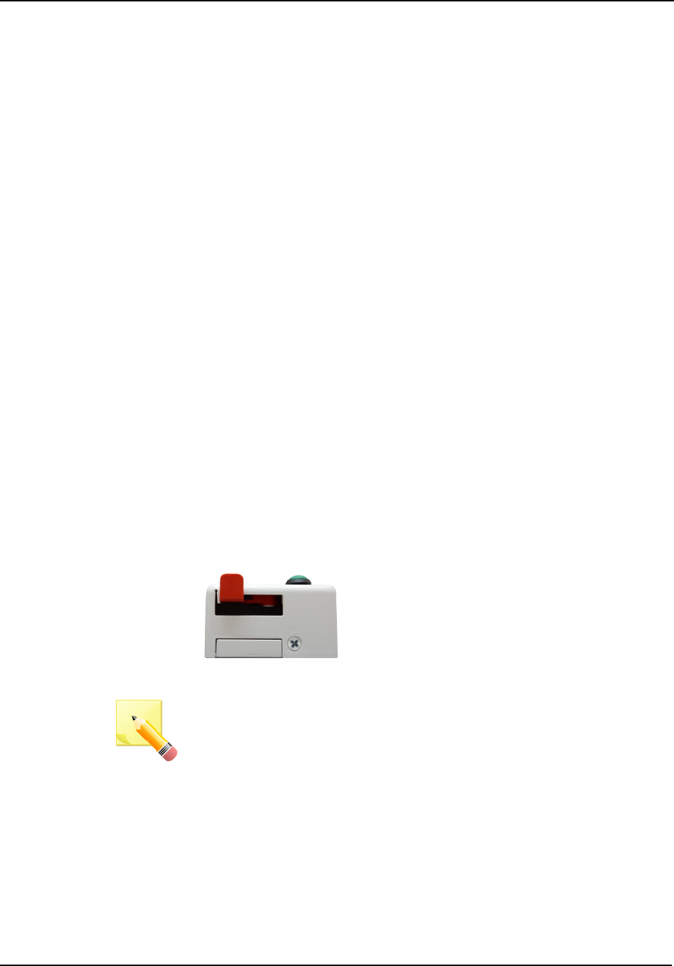
Chapter 2 – Installing End Devices
Page 40 of 77 Quick Response Premiere Hardware Installation Guide
0510-1099-I
The second light is a green LED and is only activated by moving a jumper
(JP3) in place on the electronics inside the device. It is only recommended
that this be activated for service purposes only by trained service
personnel as its blinks are used for diagnostic purposes. When the jumper
is in place and the unit reinstalled in its original location the green light will
blink much fainter than the red alarm LED. The following is how the green
LED is coded:
One green blink = message sent, but no acknowledgment was
received from Gateway
Two green blinks = all nearby Routers full
Three green blinks = checkin/alarm message was sent
successfully with an acknowledgment received from Gateway
Ten green blinks = device received new configuration data
Mounting
To mount a call station:
1. The QR Premiere Call stations are surface mounted. A height of 48
inches is standard, however; mounting heights may vary. Before
mounting to the wall, pull the plastic battery tabs to activate the
battery pack.
2. Using the rear plate of the call station as a template, place it level
against the wall at the desired mounting height and mark the location
of the two mounting holes.
3. Center punch each hole and install two nylon wall anchors (included).
If the call station is located on a concrete wall then you must use the
wall anchors designed for use with concrete (not included).
4. Snap the front assembly over the rear plate and place a screw
(included) into the bottom of the assembly (as shown below) to
secure.
NOTE: For Pull Cords, determine the desired length of the red Pull Cord
string. The standard length of a Pull Cord strings is six feet long. However,
as mounting heights vary, the length of the string may need to be
adjusted.
To adjust the length of the Pull Cord string:
1. Gently pop the red alarm lever free from the enclosure and remove
the string.
2. Cut the string to the desired length and rewind it on the alarm lever in
the reverse order it was removed. There are instructions printed on
the side of the red alarm lever for assistance in winding the string.
3. Press the red alarm lever back onto the enclosure and route the pull
cord string through the small slit in the bottom corner of the enclosure.
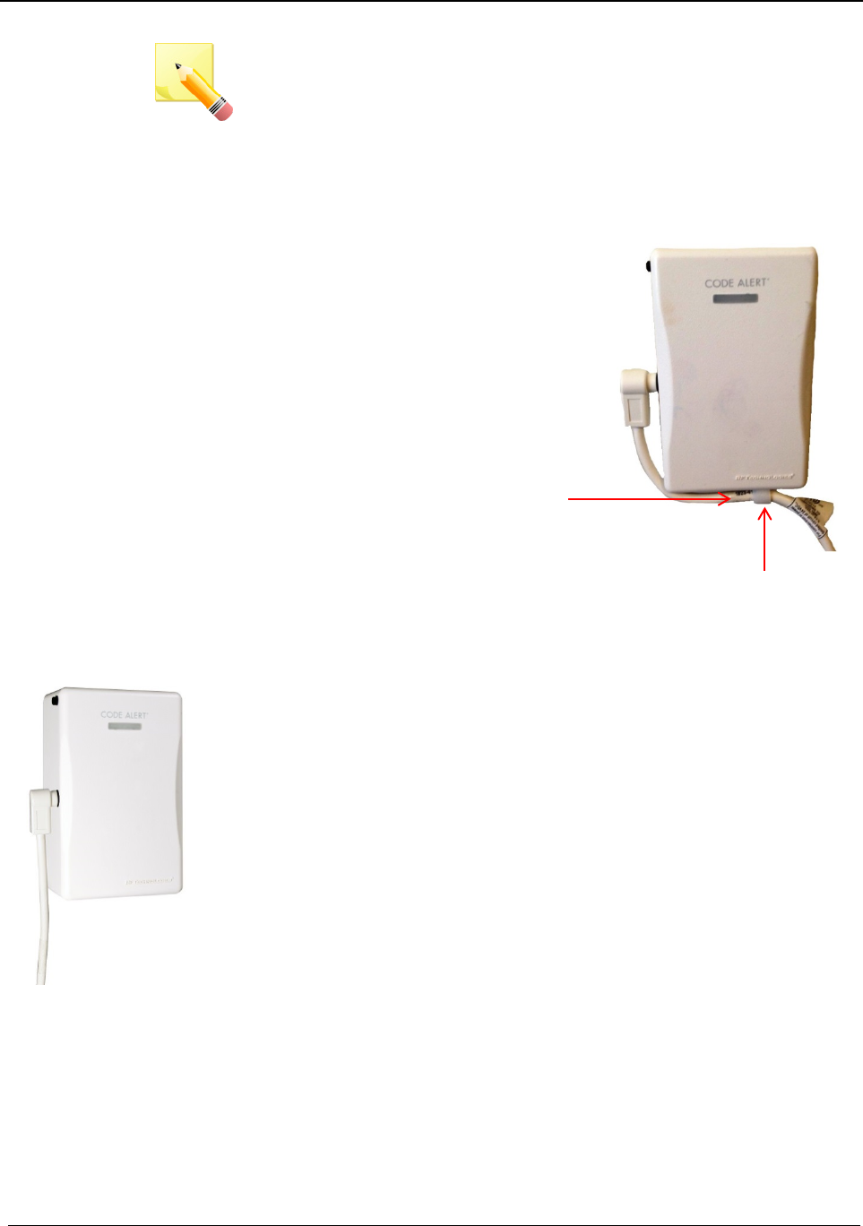
Chapter 2 – Installing End Devices
Quick Response Premiere Hardware Installation Guide Page 41 of 77
0510-1099-I
NOTE: Prior to any Call Device setup, the devices must be assigned to a
unit. This is what allows the device to be seen in the Event List. Refer to
the Software Administrator Guide for additional information.
Add Retention
If excessive pulling on the nurse call cord results in the Nurse Call Jack
breaking free from the wall plate, the solution is to add retention to the
nurse call cord (0800-0554 Nurse call Cord Retention Hardware, 10
pack). This retention increases the strength that the enclosure can
withstand.
To add retention hardware to the nurse
call cord:
1. Remove the enclosure cover screw
on the bottom side of the Nurse Call
Jack device.
2. At approximately three inches from
the nurse call cord’s plug, slip the
white plastic cord clamp over the
cord.
3. Place the flat side of the cord clamp
up against the bottom side of the
Nurse Call Jack device with the hole
in the cord clamp in alignment with
the enclosure cover screw hole.
4. Replace the original screw that was just removed with the pan head
screw. Tighten in place.
Nurse Call
A Nurse Call station is affixed near the bed of the patient. An Assistance
Required alarm event is reported in the Event List when a patient pushes
the button on the Nurse Call cord. The Nurse Call station is supervised; a
routine check in message is sent from the transceiver and if the signal is
not received by the system, a Device Fault event is generated in the
Event List at the computer.
To setup a nurse call station for use:
1. Plug in the desired Nurse Call Cord set into the Nurse Call station.
2. Activate the Nurse Call by pressing the button on the cord set.
3. If the Nurse Call station is working properly, an Assistance Required
alarm event will be listed on the Event List at the Central Server. The
system senses the Nurse Call when it goes into alarm and adds it to
its list of devices.
4. For latching type cord sets reset the Nurse Call station by pulling the
button back to the UP position. Momentary type cord sets can be
reset by pressing the reset button on the side of the device. The alarm
event will automatically clear from the Event List at the Central Server.
If Enforce Joint Commission is enabled, you must clear the alarm at
the Central Server or Client computer by selecting a reason.
5. At the Central Server, update the Nurse Call station information, for
example, giving the Nurse Call a name and/or assigning it to a room
or unit. Refer to the “Update Devices” section in the applicable
Software Administrator Guide.
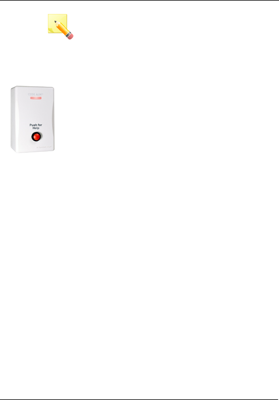
Chapter 2 – Installing End Devices
Page 42 of 77 Quick Response Premiere Hardware Installation Guide
0510-1099-I
NOTE: To configure the nurse call for momentary or latching style call
cords, make sure the jumper JP2 is set to the following:
Momentary: MOM
Latching: LAT
Push Button
Emergency Call
A Push Button Emergency Call is mounted on the wall. This device is
used to request staff assistance and is commonly used in common areas
and lunch rooms.
An Assistance Required alarm event is reported in the Event List when a
patient pushes the red button. The Push Button Emergency Call is
supervised; a routine check in message is sent from the Push Button
Emergency Call and if the signal is not received by the system, a Device
Fault event is generated in the Event List at the computer.
To setup a push button call station for use:
1. Activate the Push Button Emergency Call station by pushing the red
button. When pushed, the button remains in a recessed position
indicating the device is in an alarm state.
2. If the Push Button Emergency Call station is working properly, an
Assistance Required alarm event will be listed on the Event List at the
Central Server. The system senses the Push Button Emergency Call
when it goes into alarm and adds it to its list of devices.
3. Reset the Push Button Emergency Call by pushing the red button
again, the button pops out indicating the transceiver has changes
states and is now idle and ready for its next usage.
4. The alarm event will automatically clear from the Event List at the
Central Server. If Enforce Joint Commission is enabled, you must
clear the alarm at the Central Server by selecting a reason.
5. At the Central Server, update the Push Button Emergency Call
information, for example, giving the Push Button Emergency Call a
name and/or assigning it to a room or unit. Refer to the “Update
Devices” section in the applicable Software Administrator Guide.
Pull Cord
A Pull Cord is mounted on the wall. This device is used to request staff
assistance and is commonly used in bedrooms and bathrooms. It is
suitable for use in close proximity to showers or baths; however to prevent
damage, avoid any submersion.
An Assistance Required alarm event is reported in the Event List when a
patient pulls a cord. The Pull Cord is supervised; a routine check in
message is sent from the transceiver and if the signal is not received by
the system, a Device Fault event is generated in the Event List at the
computer.
To setup a pull cord call station for use:
1. Activate the Pull Cord by pulling the cord.
2. If the transceiver is working properly, an Assistance Required alarm
event will be listed on the
3. Event List at the Central Server. The system senses the pull cord
station when it goes into alarm and adds it to its list of devices.
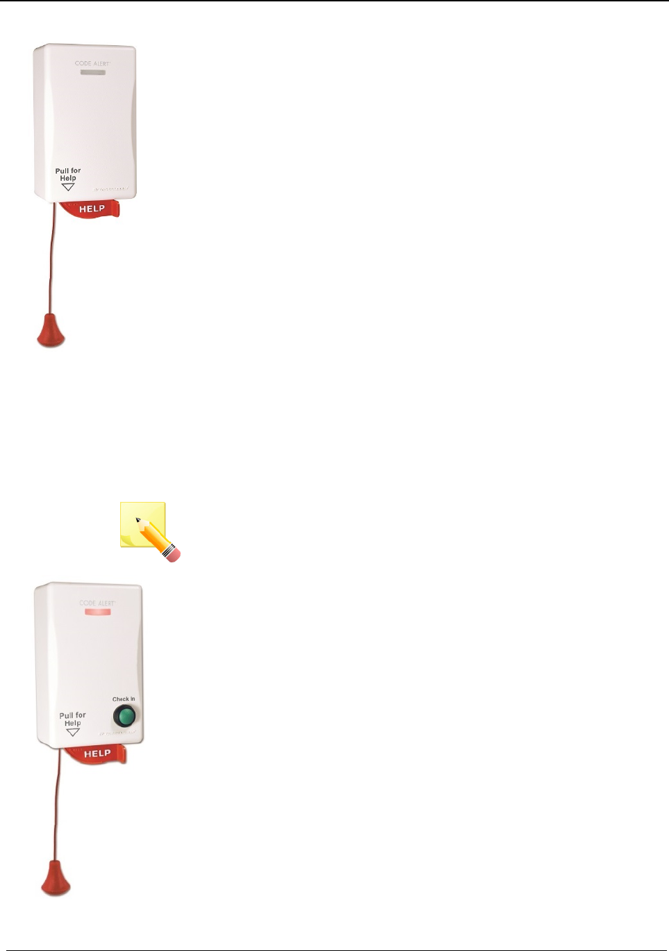
Chapter 2 – Installing End Devices
Quick Response Premiere Hardware Installation Guide Page 43 of 77
0510-1099-I
4. Reset the Pull Cord by rotating the red HELP lever back to the UP
position.
5. The alarm event will automatically clear from the Event List at the
Central Server. If Enforce Joint Commission is enabled, you must
clear the white alarm at the Central Server by selecting a reason.
6. At the Central Server, update the Pull Cord information, for example,
giving the Pull Cord a name and/or assigning it to a room or unit.
Refer to the “Update Devices” section in the applicable Software
Administrator Guide.
Pull Cord with
Check-In
A Pull Cord with Check In enables the staff or patient to push a green
button to check-in. Pressing the green button indicates to the system that
the patient has checked in or been visited by staff. The type of check-in
depends on how your Pull Cord with Check In is configured (refer to the
applicable Software Administrator Guide). For various types of check in
see below.
NOTE: Setup for the pull cord with check-in is the same as the pull cord
station listed above.
Check-in types
Patient Check In: A patient pushes the button to notify the staff
that he/she is awake and does not require assistance.
Staff Check In: A staff member pushes the check-in button
once they have checked on a patient.
Staff Care Complete: A staff member pushes the check-in
button in response to an Assistance Required alarm once the
patient has been checked on and the alarming device is reset. If
Joint Commission is enforced, this will clear the White alarm from
the Client computer

Chapter 2 – Installing End Devices
Page 44 of 77 Quick Response Premiere Hardware Installation Guide
0510-1099-I
Battery
Replacement
The QR Premiere Call Stations are powered by 4 replaceable AA
batteries.
To replace the AA Batteries for the Call Stations:
1. Remove the Nurse Call transceiver from its mounted location by first
removing the screw on the bottom of the enclosure.
2. Rotate the enclosure upward and remove from wall. The four AA
batteries will be visible. There is no need to disassemble anything as
the batteries are removable as they are. Pull all four batteries free
from the battery holder.
NOTE: Do not use a metal screwdriver or metallic instrument to remove
the battery. This may damage the device.
3. Insert four new AA Lithium Ion batteries into the battery holder. Make
sure to pay attention to the polarity of the batteries within their holder.
4. Verify communication is resumed by alarming the Nurse Call
transceiver and observing the LED through the front of the Nurse Call
transceiver. It should be blinking red.
5. Once communication is verified replace the front cover of the Nurse
Call transceiver and remount it to the wall mounting plate.
Universal
Transceiver
A Universal transceiver can be used to integrate your facility’s existing
equipment such as backup generators or other devices that can be
integrated with the software. Universal transceivers can be programmed
as either NO (normally open) or NC (normally closed) devices. They
automatically activate when the input from a monitored device has a
contact close or open. When this happens, the Universal transceiver
sends event information to the Central Server. The Universal transceiver
is powered by a replaceable 3V coin cell battery.
To wire the Universal transceiver connect the two 22-gauge, 2-conductor
stranded wire into the appropriate terminals on the existing device. Refer
to the device manufacturer’s instructions or contact the RF Technologies,
Inc. Technical Support Team at (800)-669-9946 or (262) 790-1771 to
identify the correct terminals.
Display
The Universal has one (1) LED light. The light is visible when enclosure
door is open (i.e. during installation), but not visible during normal
operation when the enclosure door is closed. The light flashes briefly once
every check-in (20 minutes by default) and once each time the device
alarm is triggered or cleared. Green indicates communication with the
Router is good; red indicates communication failure and device is not able
to transmit to the Router.
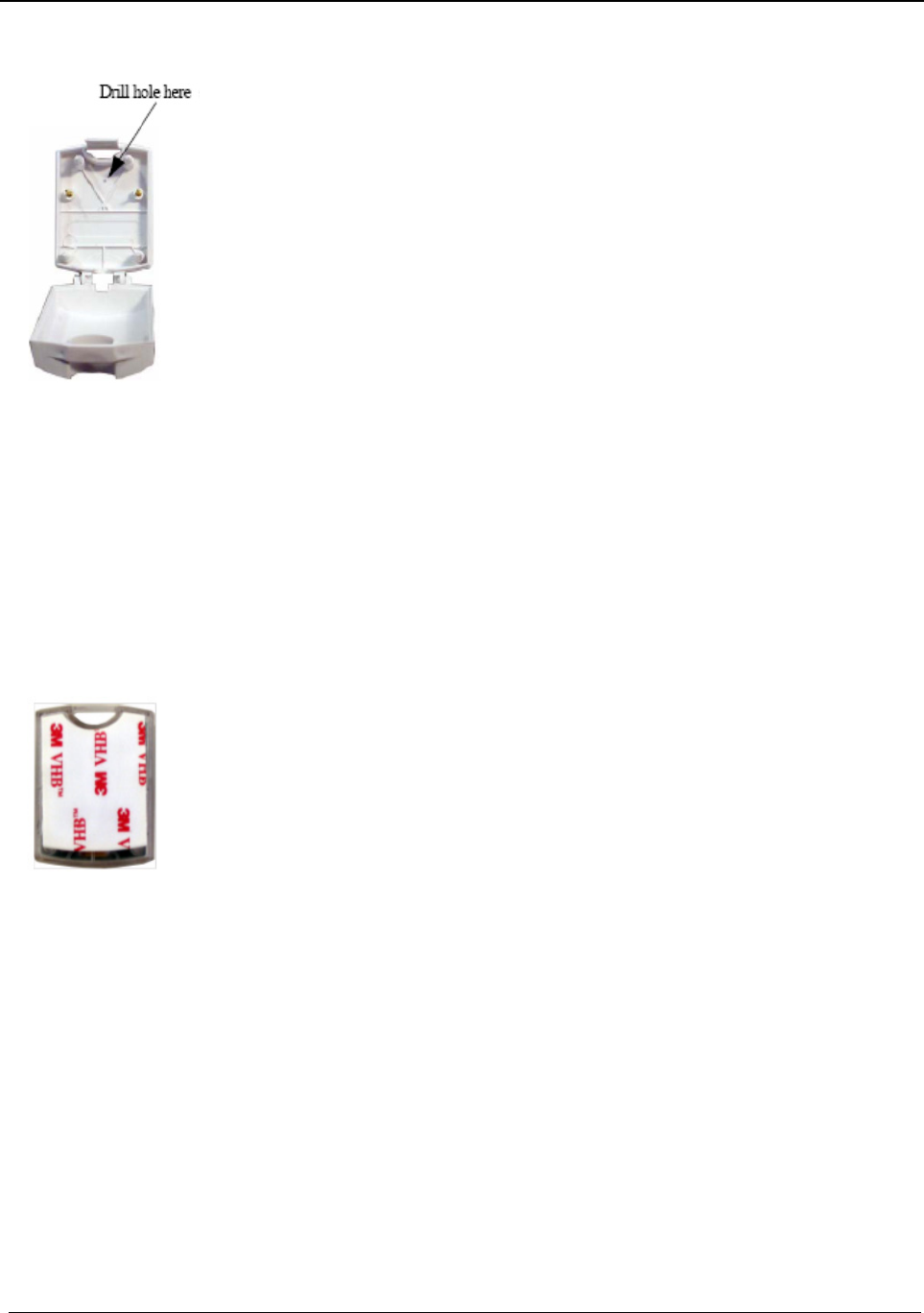
Chapter 2 – Installing End Devices
Quick Response Premiere Hardware Installation Guide Page 45 of 77
0510-1099-I
Mounting
The Universal transceiver can be mounted with a screw using a mounting
hole; it can be applied with the attached adhesive pad; or it can be
mounted with a lanyard or zip tie through the opening at the top of the
transceiver.
To mount the Universal transceiver using mounting hole:
1. Use your fingers to open the front cover of the transceiver by pushing
the retaining clip on the top downward. This allows the hinged cover
to drop down and expose the circuit board.
2. Carefully pull the circuit board free from the pins on the enclosure.
3. Drill a 1/8 inch mounting hole through the indentation in the
transceiver enclosure.
4. Using the enclosure of the Universal transceiver as a template, place
it level against the wall and mark the location of the mounting hole.
5. Mark out the mounting hole and drill a 1/16 inch diameter hole where
you made the mark.
6. Line up the hole on the transceiver enclosure with the newly drilled
hole and mount the enclosure to the door frame using a number 6
screw (not included).
7. Pull the plastic battery tab to activate the battery or refer to the section
entitled “To replace the battery in a Universal transceiver” on page 46
to insert a new battery.
8. Return the circuit board onto the two pins.
9. Snap the front cover of the transceiver back into place.
To mount the Universal transceivers with adhesive pad:
1. Remove an adhesive pad from the strip of paper.
2. Place the transceiver face down.
3. Line the adhesive pad up with the back of the transceiver.
4. Apply the adhesive pad.
5. Verify that the pad is applied correctly and is not hanging over the
sides of the transceiver.
6. Determine where you want to apply the transceiver. The surface must
be clean, dry and free of condensed moisture.
7. Remove the plastic battery tab to activate the battery or refer to the
section entitled “To replace the battery in a Universal transceiver” on
page 46 to insert a new battery.
8. Remove the adhesive plastic guard.
9. Firmly attach the transceiver to the mounting surface. Ideal
application temperature range is 70°F to 100°F (21°C to 38°C).
10. Press firmly and hold for approximately 10 seconds to activate the
pressure sensitive adhesive.
11. After application, the bond strength will increase as the adhesive
flows onto the surface. At room temperature, approximately 50% of
ultimate bond strength will be achieved after 20 minutes, 90% after 24
hours and 100% after 72 hours.
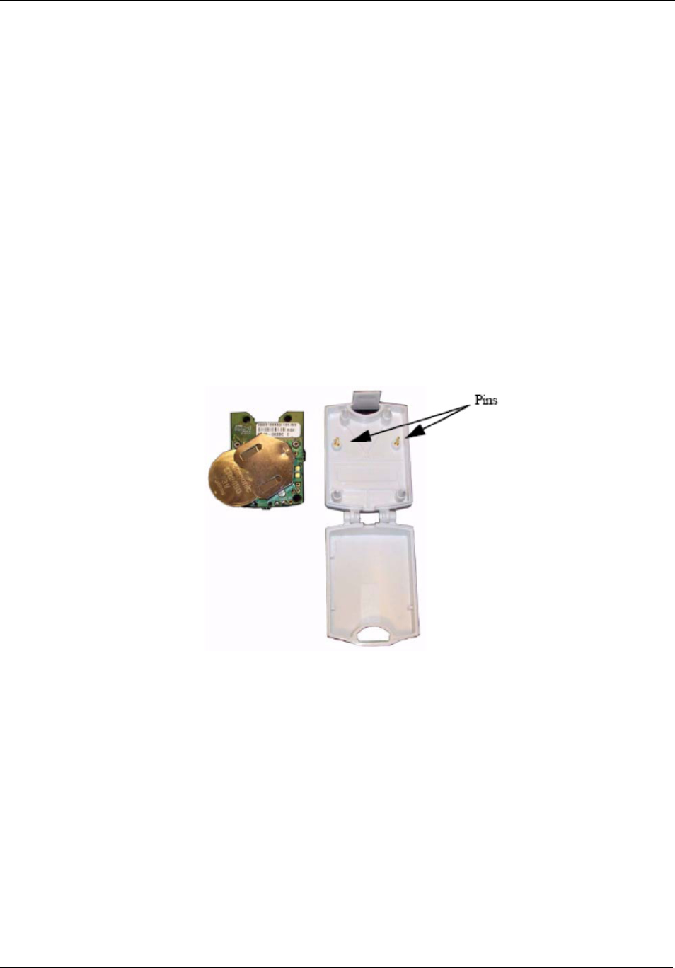
Chapter 2 – Installing End Devices
Page 46 of 77 Quick Response Premiere Hardware Installation Guide
0510-1099-I
To set up the Universal transceiver for use:
1. Activate the Universal transceiver by inserting the battery or remove
the plastic battery tab.
2. Test the transceiver by activating the existing device.
3. If the transceiver is working properly, the Central Server will sense the
Universal when it goes into alarm and add it to the list of devices.
4. At the Central Server, update the transceiver information, for
example, giving it a name and/or assigning it to a room or unit. Refer
to the “Update Devices” section in the Software Administrator Guide.
Battery
Replacement
To replace the Universal Transceiver battery:
1. Use your fingers to open the front cover of the transceiver by pushing
the retaining clip on the top downward. This allows the hinged cover
to drop down and expose the circuit board.
2. Carefully pull the circuit board free from the pins on enclosure.
3. If changing the battery, use a small, non-conductive piece of plastic or
wood to push the 3V Lithium coin cell battery from the rear of the
battery clip until it pops free.
NOTE: Do not use a metal screwdriver or metallic instrument to remove
the battery. This may damage the device.
4. Insert the 3V Lithium coin cell battery into the battery holder as
shown. Be sure to align the positive (+) end of the battery as marked
on the battery and battery holder.
5. Verify communication by observing the LED light.
6. Return the circuit board onto the two pins.
7. Once communication is verified, snap the front cover of the
transceiver back into place.
Tamper
The tamper functionality operates in several modes depending on the
device and the type of tamper interference. In either case, when initiated,
a Tamper alarm event will be listed on the Event List at the Central
Server.
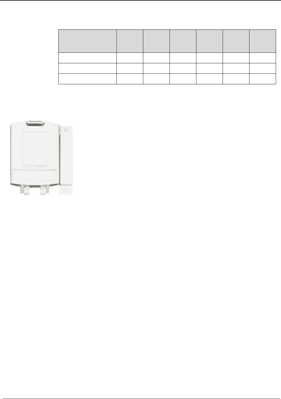
Chapter 2 – Installing End Devices
Quick Response Premiere Hardware Installation Guide Page 47 of 77
0510-1099-I
Below is a table showing the type of tamper event associated with a
particular device.
Tamper Nurse
Call
EAC Door/
Window
Door
Manual
Reset
Door
Check-
In
PIR
Case Open x x x x x x
External Enclosure x
Cord Removed x
Door/Window
Transceiver
A Door/Window transceiver is used to protect a door or window against
unauthorized egress. An Exit alarm event is reported in the Event List
when a monitored door or window is opened. The alarm automatically
clears when the door or window is closed. The Door/Window transceiver
is supervised; if no information is received by the system from the
transceiver for a specified number of minutes, a Device Fault alarm is
generated in the Event List at the computer.
The Door/Window transceiver comes in two pieces: the transceiver
enclosure and a magnet. The magnet is attached directly to the door or
window. The transceiver enclosure is mounted on the door or window
frame and can be mounting with the attached adhesive pad or a screw.
An alarm triggers when the devices are separated. The Door/Window
transceiver is powered by a replaceable 3V coin cell battery.
Display
The Door/Window transceiver has one (1) LED light. The light is visible
when enclosure door is open (i.e. during installation), but not visible during
normal operation when the enclosure door is closed. The light flashes
briefly once every check-in (20 minutes by default) and once each time
the device alarm is triggered or cleared. Green indicates communication
with the Router is good; red indicates communication failure and device is
not transmitting to the Router.
Mounting
To mount the Door/Window magnet to the door or window:
NOTE: When mounting the Door/Window magnet on a door, there is a
better sensitivity if the magnet is mounted closer to the opposite edge
from the hinges.
1. Determine placement of the magnet. The distance between the reed
switch in the transceiver and the magnet must be no more than 1/2
inch.
2. Using the Door/Window transceiver magnet as a template, place it
level against the door or window and mark the location of the two
mounting holes.
3. Drill holes where you made the marks.
4. Line up the holes on the magnet with the newly drilled holes and
mount the magnet using the screws provided.

Chapter 2 – Installing End Devices
Page 48 of 77 Quick Response Premiere Hardware Installation Guide
0510-1099-I
To mount the Door/Window transceiver using mounting hole:
NOTE: Orientate the internal reed switch next to magnet 3/8 inch away.
The Universal transmitter has been tested and shown to work as far as
1/2 inch.
1. Use your fingers to open the front cover of the transceiver by pushing
the retaining clip on the top downward. This allows the hinged cover
to drop down and expose the circuit board.
2. Carefully pull the circuit board free from the pins on the enclosure.
3. Drill a 1/8 inch mounting hole through the indentation in the
transceiver enclosure.
4. Hold the enclosure against the door/window frame so that when the
circuit board is in place, the internal reed switch faces the magnet on
the door.
5. Mark out the mounting hole and drill a 1/16 inch diameter hole where
you made the mark.
6. Line up the hole on the transceiver enclosure with the newly drilled
hole and mount the enclosure to the door frame with a number 6
screw (not included).
7. Pull the plastic battery tab to activate the battery or refer to the section
entitled “To replace the battery on a Door/Window transceiver” on
page 51.
8. Return the circuit board onto the two pins.
9. Snap the front cover of the transceiver back into place.
To mount the Door/Window transceiver using mounting plate:
When mounting to a door or window jamb whose width is less than the
width of the Door/Window transceiver, use the provided plastic mounting
plate.
1. Determine the location of the Door/Window transceiver.
2. Place the mounting plate in this location and mark the two mounting
holes on the jamb.
3. Pre-drill the two holes using a 9/64" drill in the two marked locations.
4. Mount the plate using the screws provided.
5. Proceeded to the step 2 of the next procedure, to mount the
Door/Window transceivers with adhesive pad.

Chapter 2 – Installing End Devices
Quick Response Premiere Hardware Installation Guide Page 49 of 77
0510-1099-I
To mount the Door/Window transceivers with adhesive pad:
The Door/Window transceiver can be attached using an adhesive pad that
can be purchased with the transceiver.
1. Determine where you want to mount the transceiver. The mounting
surface must be clean, dry and free of condensed moisture.
2. Pull the plastic battery tab to activate the battery or refer to the section
entitled “To replace the battery on a Door/Window transceiver” on
page 51 to insert a new battery.
3. Remove the adhesive plastic guard.
4. Hold the enclosure against the door/window frame so that when the
circuit board is in place, the internal reed switch faces the magnet on
the door.
5. Firmly attach the transceiver to the door/window frame (or mounting
plate). Ideal application temperature range is 70°F to 100°F (21°C to
38°C).
6. Press firmly and hold for approximately 10 seconds to activate the
pressure sensitive adhesive.
7. After application, the bond strength will increase as the adhesive
flows onto the surface. At room temperature, approximately 50% of
ultimate bond strength will be achieved after 20 minutes, 90% after 24
hours and 100% after 72 hours.
Door/Window
Transceiver
w/Reset Button
If your Door/Window transceiver comes with a reset button, the alarm
must be reset at the door by pressing the reset button once the
door/window is closed. The Door/Window transceiver comes in three
pieces: the transceiver enclosure, a magnet and a reset button. There are
two types of reset buttons.
Round Push Button (resets the transceiver)
Emergency (momentarily changes the state of the transceiver
from normally closed to open, or from normally open to closed for
as long as you push the button)
Mounting
To mount the Door/Window transceiver with reset button:
1. Mount the Door/Window magnet. The distance between the reed
switch in the transceiver and the magnet must be no more than 1/2
inch.
2. Mount the Door/Window transceiver. Orientate the internal reed
switch next to the magnet 3/8 inch away.
3. The Universal transceiver comes pre-wired with 4 feet of 2- conductor
22 gauge wire. Route wire into door or window jamb and to the
desired reset button location.
4. Mount the reset button.

Chapter 2 – Installing End Devices
Page 50 of 77 Quick Response Premiere Hardware Installation Guide
0510-1099-I
To mount the reset button that has the round push button:
1. Use your fingers to remove the front cover.
2. Using the base of the reset button as a template, place it level against
the door or wall and mark the location of the two mounting holes.
3. Drill holes where you made the marks.
4. Line up the holes on the base of the reset button with the newly drilled
holes and mount the base using the screws provided.
5. Snap the front cover of the reset button back onto the base.
To mount the reset button that is labeled EMERGENCY:
1. Using the reset button as a template, place it level against the wall or
door and mark the location of the two mounting holes.
2. Drill holes where you made the marks.
3. Line up the holes on the base of the reset button with the newly drilled
holes and mount the reset button using the screws provided.
To set up the Door/Window transceiver for use:
1. Activate the Door/Window transceiver by opening the door or window.
2. If the transceiver is working properly, an Exit alarm event will be listed
on the Event List at the Central Server. The system senses the
Door/Window transceiver when it goes into alarm and adds it to its list
of devices.
3. Reset the Door/Window transceiver by closing the door or window
and pressing the reset button if applicable.
4. If the transceiver is reset properly, the alarm event will automatically
clear from the Event List at the Central Server. If Enforce Joint
Commission is enabled, you must clear the alarm at the Central
Server by selecting a reason.
5. At the Central Server, update the Door/Window transceiver
information, for example, giving it a name and/or assigning it to a
room or unit. Be sure to enable the Inactivity Check-In feature and
select beginning and end times. Refer to the “Update Devices” section
in the applicable Series Software Administrator Guide.
Battery
Replacement
To replace the Door/Window Transceiver battery:
1. Use your fingers to open the front cover of the transceiver by pushing
the retaining clip on the top downward. This allows the hinged cover
to drop down and expose the circuit board.
2. Carefully pull the circuit board free from the pins on enclosure.
3. If changing the battery, use a small, non-conductive piece of plastic or
wood to push the 3V Lithium coin cell battery from the rear of the
battery clip until it pops free.

Chapter 2 – Installing End Devices
Quick Response Premiere Hardware Installation Guide Page 51 of 77
0510-1099-I
NOTE: Do not use a metal screwdriver or metallic instrument to remove
the battery. This may damage the device.
4. Insert the 3V Lithium coin cell battery into the battery holder as
shown. Be sure to align the positive (+) end of the battery as marked
on the battery and battery holder.
5. Verify communication by observing the LED light.
6. Return the circuit board onto the two pins.
7. Once communication is verified, snap the front cover of the
transceiver back into place.
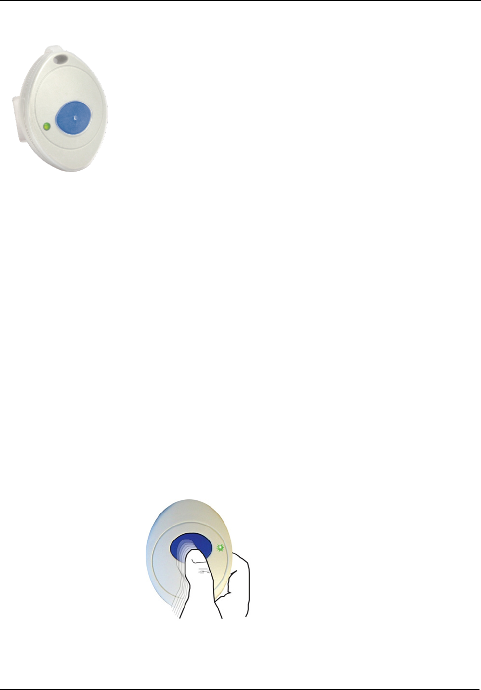
Chapter 2 – Installing End Devices
Page 52 of 77 Quick Response Premiere Hardware Installation Guide
0510-1099-I
Pendants
The Pendant is a wireless, mobile transceiver that can be worn around the
neck or wrist, or attached to a belt. The protective boot protects the
Pendant against dropping and water ingress. However, to prevent water
damage, avoid prolonged submersion and direct contact with a water
stream.
The Pendant can be supervised; if no information is received by the
system from the Gateway for a specified supervision time, a No Signal
alarm is generated in the Event List at the computer. Since the Pendant is
a mobile device, no installation is required.
Display
The Pendant has one (1) light that is visible from the outside of the
enclosure. The light flashes 3 times in rapid succession when the alarm is
triggered or cleared. A green light indicates communication with the Gate-
way/Router is good; red indicates communication failure and the device is
not transmitting to the Gate-way/Router.
Activate
To activate the pendant:
The Pendant is shipped with a replaceable 3V coin cell battery. To
activate the battery, use your fingers to re-move the back cover and pull
out the plastic battery tab. Be sure the battery stays in the battery holder
while the plastic tab is removed. Additionally, make certain that you are
not pressing on the blue button while activating the battery.
To setup the pendant for use:
1. With the Pendant within range of the system, alarm the Pendant by
pressing and releasing the blue button. If the alarm message has
been delivered successfully, the green light will flash 3 times.
2. The green light will then blink once every 3 seconds while the
Pendant remains in alarm. The system senses the Pendant when it
goes into alarm.
3. Reset the Pendant by pressing the button six times with less than 1
second between presses. The green light will flash each time the
button is pressed.
4. If the alarm clear message has been delivered successfully, the green
light will flash 3 times. The green light will no longer blink once every
3 seconds.
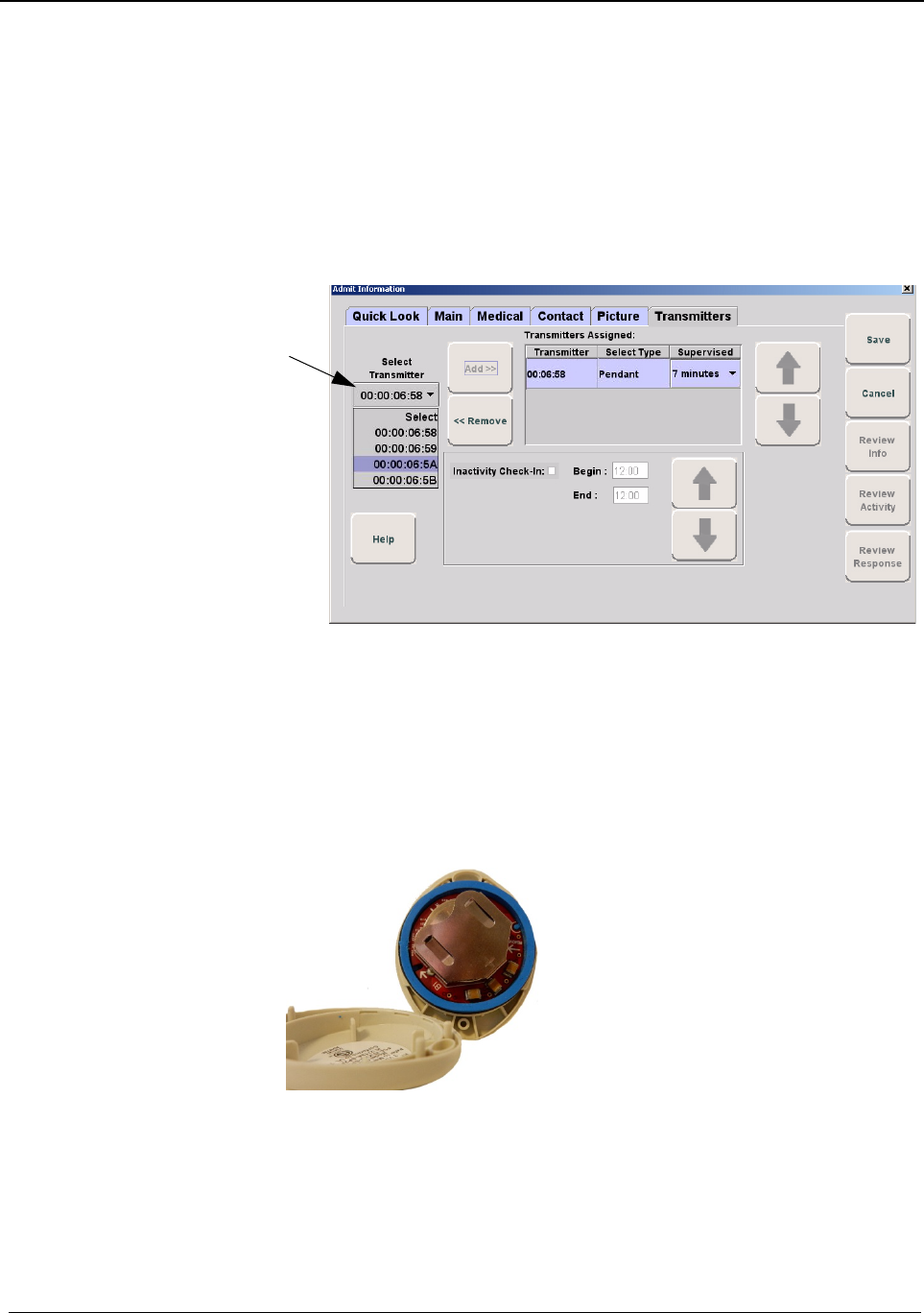
Chapter 2 – Installing End Devices
Quick Response Premiere Hardware Installation Guide Page 53 of 77
0510-1099-I
5. The pendant is now ready to be assigned. Verify the Pendant appears
in the Select Transmitter pull-down in the patient’s Admit Information
window, Transmitter tab.
To verify Pendant transceiver appears in the system:
1. Login then click Manual Admit
2. Select the Transmitters tab.
3. Verify that the Pendant ID number (last four numbers printed on the
Pendant) appears in the Select Transmitter pull-down.
Battery
Replacement
RF Technologies uses only Panasonic 3.0 V Coin Cell Lithium Battery
model # CR 2450. These batteries provide 10 to 30 percent more power
than other batteries of the same size.
To replace a battery in a Pendant:
1. Remove the protective boot from around the pendant
2. Use your fingers to remove the back cover of the Pendant and expose
the circuit board. The battery holder is in plain view.
3. Tilt the circuit board back a few degrees (the battery should be
replaced without removing the circuit board from the enclosure)
4. When changing the battery, use a small, non-conductive piece of
plastic or wood to push the 3V Lithium coin cell battery from the rear
of the battery holder until it pops free.
NOTE: Do not use a metal screwdriver or metallic instrument to remove
the battery. This may damage the device.

Chapter 2 – Installing End Devices
Page 54 of 77 Quick Response Premiere Hardware Installation Guide
0510-1099-I
5. Push the circuit board back into the enclosure so that it sits flush and
the alignment ribs are seated correctly
6. Press the blue button on the pendant (you should hear a click) a few
times to ensure no charge is remaining in the circuits
7. Insert the new 3V Lithium coin cell battery into the battery holder. Be
sure to align the positive (+) end of the battery as marked on the
battery upward and into the battery holder.
8. Carefully align the back cover of the pendant over the front enclosure
before snapping into place (wiggling the back cover slightly will help it
slide over the black O-ring on the other half of the pendant enclosure).
Avoid twisting the cover as this may dislodge the O-ring,
compromising its water resistance.
9. Snap the back cover back onto the pendant.
10. Replace the protective boot
11. The pendant should be tested to verify proper working order

Chapter 2 – Installing End Devices
Quick Response Premiere Hardware Installation Guide Page 55 of 77
0510-1099-I
NOTE: When inserting the replacement battery for the Pendant,
inadvertently holding the blue button down while inserting the battery may
place the Pendant transceiver into Survey Mode.
12. Verify light communication.
13. When replacing the battery to a Pendant containing a model # CR
2450 battery, to maintain the Pendant’s water resistance, a small
coating of silicon grease on the o-ring is beneficial. Break open the
tube and with a small dab on the finger, apply a thin coat of the
silicone grease to the circumference of the o-ring on the top half of the
enclosure. Wipe off any excess.
NOTE: Do not use Petroleum Jelly (Vaseline) to grease the o-ring as it will
destroy the o-ring material.
14. Carefully align the back cover of the Pendant to the front enclosure
before snapping into place. Avoid twisting the cover; twisting may
dislodge the o-ring, compromising its water resistance.
15. Snap the back cover back onto the Pendant.
LED Light
Indicators
The Universal and Pendant transceivers contain a two-color indicator
light. In general, green indicates good and red indicates bad.
No light: If the LED indicator does not blink within a few
seconds of alarming or clearing an alarm, this may indicate a
dead battery; try replacing the battery. If the problem persists,
contact Technical Support.
3 green blinks: Alarm, clear, or check-in had been transmitted
and a confirmation has been received from the Gateway.
10 green blinks: Device has successfully received new
configuration data from the computer.
1 green blink: Alarm, clear or check-in has been transmitted but
the device has not yet received a confirmation from the Gateway.
Wait up to 15 seconds for the device to try again by itself; do not
re-alarm the device. The Pendant will also blink green once each
time the blue button is pressed; as visual feedback that the
button press was recognized.
1 red blink: Device cannot find a Router to communicate with;
device may be out of range or on the wrong channel. For the
Pendant model #9600-0251, the battery maybe too weak.
2 red blinks: Join failed; the device found one or more Routers,
but Routers indicate they cannot accept any additional devices.
An additional Router may need to be added to support a large
number of devices in the same area.
3 red blinks (Pendant model #9600-0251): Message sent to
local Router parent, but device did not get an acknowledgement
back from the Gateway. Gateway may have lost power, or all
communication paths to Gateway are broken.
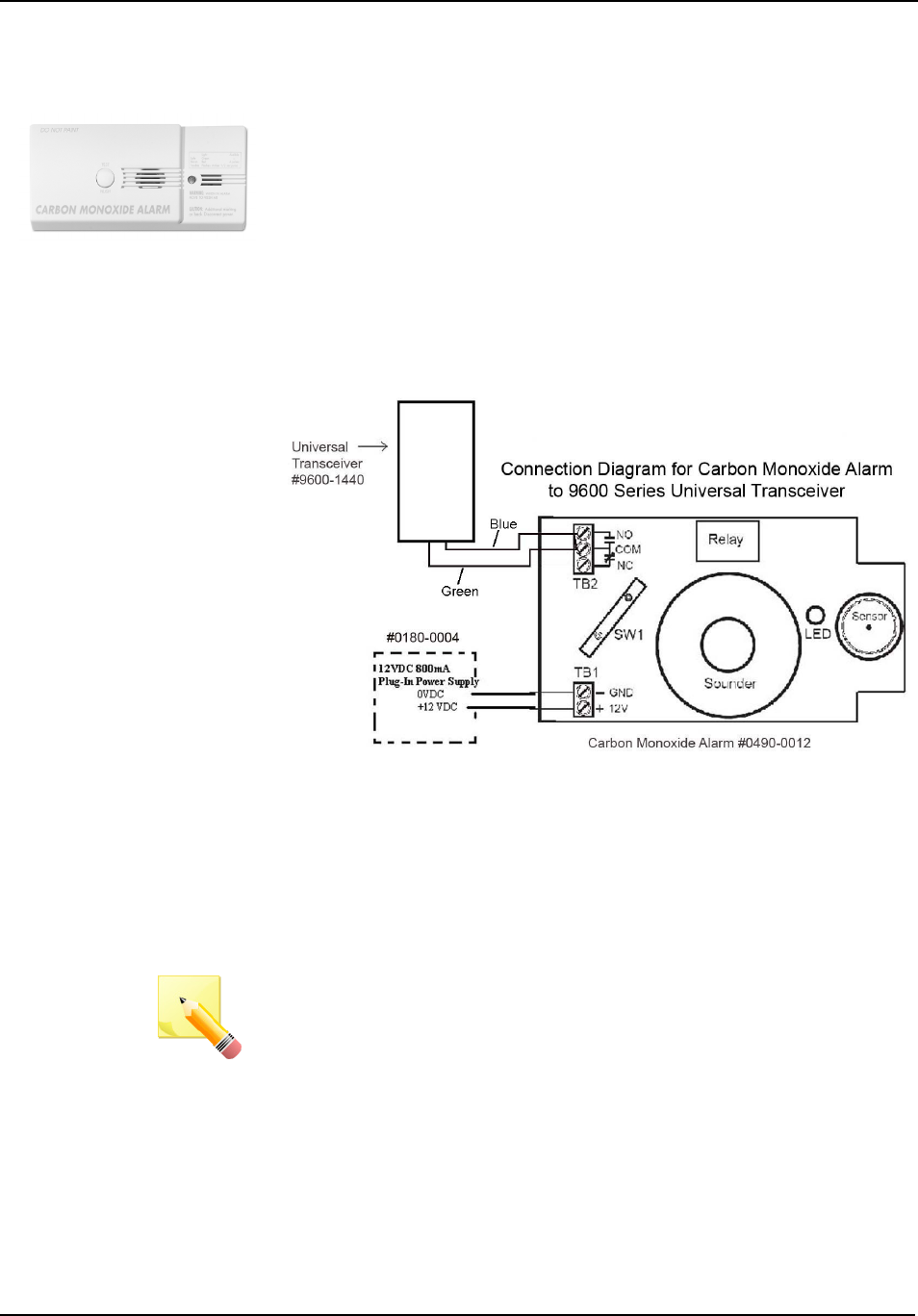
Chapter 2 – Installing End Devices
Page 56 of 77 Quick Response Premiere Hardware Installation Guide
0510-1099-I
Carbon
Monoxide
The Pendant is a wireless, mobile transceiver that can be worn around the
neck or wrist, or attached to a belt. The protective boot protects the
Pendant against dropping and water ingress. However, to prevent water
damage, avoid prolonged submersion and direct contact with a water
stream.
The Pendant can be supervised; if no information is received by the
system from the Gateway for a specified supervision time, a No Signal
alarm is generated in the Event List at the computer. Since the Pendant is
a mobile device, no installation is required.
Wiring
To wire the Carbon Monoxide alarm to a Universal Transceiver:
1. Remove the Carbon Monoxide Alarm from its box.
2. Remove the cover by pulling it off the back of the unit.
3. Connect the 12VDC plug-in transformer to the power terminals of the
TB1 terminal block.
4. Connect one end of the 22/2 cable to the COM and NO terminals of
the TB2 terminal block (WARNING: Be sure to use the proper
polarity).
5. While holding the two cables to the left side of the Carbon Monoxide
Alarm, replace the alarm cover. The cables fit out around the bottom
and the top cover.
NOTE: Do not run these cables through the access hole in the back of the
alarm.
Activate
To setup the carbon monoxide alarm for use:
1. Start the Software.
2. Install the battery in the Universal Transceiver.
3. Close the cover on the Universal Transceiver.
4. Plug-in the power supply connected to the Carbon Monoxide Alarm.
5. The LED on the Carbon Monoxide Alarm flashes green for
approximately 18 seconds and then remains illuminated.

Chapter 2 – Installing End Devices
Quick Response Premiere Hardware Installation Guide Page 57 of 77
0510-1099-I
6. Activate the Carbon Monoxide Alarm by placing it in alarm. Press and
hold the Test/Hush button. Once the button is pressed, the LED will
turn red. After approximately 9 seconds, the LED will start to blink red
and the alarm will be generated.
7. The system senses the Carbon Monoxide Alarm when it goes into
alarm and adds it to its Device List in Configuration.
8. Release the button; after 9 seconds the alarm will reset and the LED
will return to green.
9. At the Central Server, go to the Configuration page and update the
Carbon Monoxide Alarm information (i.e. giving it a name and/or
assigning it to a room or unit). Be sure to set the device type to CO
Detector. Refer to the "Update Devices" section in the Series 6.0
Software Administrator Guide.
10. Mount the Carbon Monoxide Alarm (and the attached Universal
Transceiver) on the wall. For more information see the manufacturer's
instructions.
11. Repeat steps 5 and 6 to test the alarm.
12. Verify that an alarm is generated in the client application’s Event List.
13. Verify the alarm clears from the Event List once the Test/Hush button
is released.
Testing the
System
After all of the components that make up the Quick Response Premiere
Wireless Call System are in place, the system-wide settings are applied,
and information specific to at least one transceiver is entered into the
database, test the operation of the entire system.
Com Port
Mapping
1. Eliminate unused com ports from mapping to reduce CPU load.
Device
Configuration
2. Go to Configuration Device Screen.
3. Verify correct channels are in use by looking at the Gateway settings
4. Verify the name of the device complies with the recommended
naming conventions. Refer to the section entitled “Naming
Conventions for the Quick Response Premiere” in the applicable
Software Administrator Guide.
5. Test the operation of the Supervision function
Confirm that all of the supervision settings are defined. Refer to
the section entitled “Configure Units” in the applicable Software
Administrator Guide.
Make a note of the number of minutes selected for Transmitter
Supervised Time.

Chapter 2 – Installing End Devices
Page 58 of 77 Quick Response Premiere Hardware Installation Guide
0510-1099-I
Dashboard
6. Verify devices powered correctly
7. Go to Dashboard screen
8. Verify all devices installed are present in Dashboard.
9. Verify all devices are named. If not named go to step 2 and name
device.
10. Verify no erroneous devices. If erroneous devices are in the
dashboard, go to step 2 and remove them.
11. Verify all firmware revisions are correct.
12. Verify device check-ins occurring at designated intervals.
Gateway is 15 seconds
Routers are 30 seconds
Pull Cords and Universals are 20 minutes
Pendants are 8 hours
Device Tree
Report
13. Go to Device Tree Report.
On the top of the screen click Comport to sort first by Comport.
Then click on Short Address to sort by Short Address.
14. Check the number of devices per router (should not exceed 12).
15. Check the number of routers, devices per gateway (should not
exceed 64).
16. Check the number of hops to gateway (should not exceed 4).
Software
Operation
17. Test the software
At the Central Server, activate a Pendant by pressing the button.
If the pendant is functioning properly, its green light will flash a
series of times, indicating that it is sending a signal.
If the software is responding, an Alarm event will be listed on the
Event List at the Central Server.
Reset the pendant by rapidly pressing the button six times. The
green light will flash each time the button is pressed. If the
transceiver is reset properly, the green light will flash a series of
times, indicating that the Reset signal is being transmitted.
If the software is responding, a Reset event will be listed on the
Event List at the Central Server.
18. Test the system for sufficient coverage
At a remote location in the facility, activate a Pendant by pressing
the button. If the pendant is functioning properly, its green light
will flash a series of times, indicating that it is sending a signal.
If there is sufficient coverage by the Routers, an Alarm event will
be listed on the Event List at the Central Server.
If your facility is using a paging system in conjunction with your
Quick Response Premiere Wireless Call System, an Alarm
message will be received by the pager.
Again at a remote location, reset the pendant by rapidly pressing
the button six times. The green light will flash each time the

Chapter 2 – Installing End Devices
Quick Response Premiere Hardware Installation Guide Page 59 of 77
0510-1099-I
button is pressed. If the pendant is reset properly, the green light
will flash a series of times, indicating that the Reset signal is
being transmitted.
If there is sufficient coverage by the Routers, a Reset event will
be listed on the Event List at the Central Server.
If your facility is using a paging system in conjunction with your
Quick Response Premiere Wireless Call System, a Reset
message will be received by the pager.
19. Repeat these steps at several locations to ensure that the pendant’s
signal is received from all areas.
Monitor System
20. Let the system run overnight.
21. Verify there are no Device Faults within the 24 hours.

Chapter 2 – Installing End Devices
Page 60 of 77 Quick Response Premiere Hardware Installation Guide
0510-1099-I
This page intentionally left blank
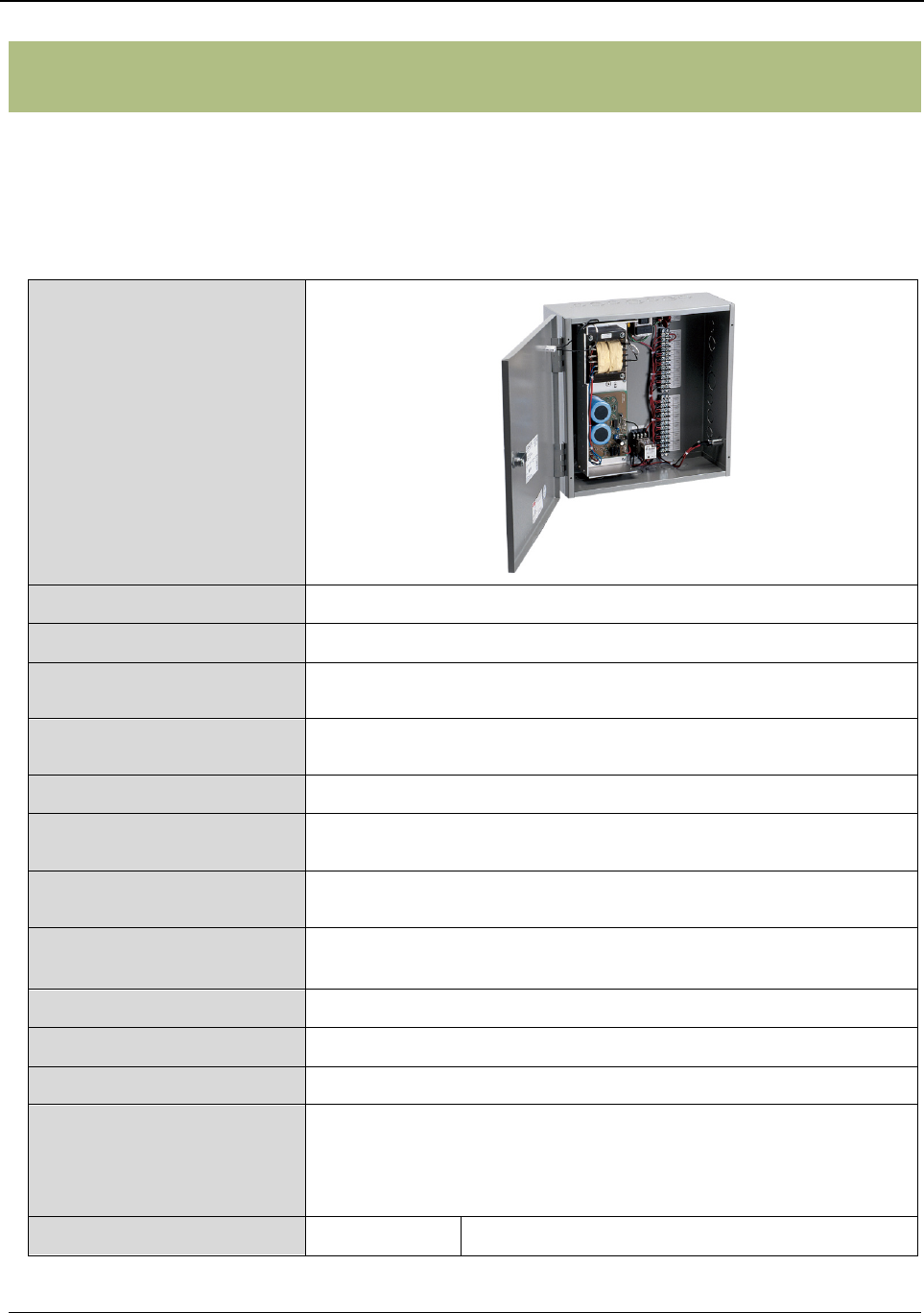
Chapter 3 – Specifications
Quick Response Premiere Hardware Installation Guide Page 61 of 77
0510-1099-I
Chapter 3 – Specifications
Introduction
This section contains information on the specifications for the Quick
Response Premiere Wireless devices, including details about the specific
requirements and certifications.
Central Power
Supply
Dimensions 16.0” L x 16.0” W x 6.0” D
Weight 30 lbs
Power Requirements 120 VAC, 3 A maximum, single-phase, stripped and trimmed
terminations
Output 15 VDC, 9 A maximum, branched into four Class 2 zones polyfused
at 2.4 A maximum
Wire Requirements 16 AWG, 2- or 4-conductor stranded CL2
Fuse AC 5 A, 120 VAC, Littlefuse 229 series Slo-Blo, 4.5 x 14.48 mm;
cartridge type, #229.005
Fuse DC 15 A, 32 V, Littlefuse 312 series, 6.35 x 31.75 mm, fast-acting
cartridge type, #312.05
Metal Oxide Varistor Surge
Protection
3 Harris, P/N: V130LA20C
Line to GND, Common to GND, and Line to Common
Operating Temperature
32-85°F, adequate ventilation required
Operating Humidity
5-93%, non-condensing
Enclosure
Gray, steel cabinet with locking door and keyswitch power on/off
Certifications UL Standard 864, Class II, Releasing Device 49XM, with Class 2
fused outputs
NFPA Standard 72, Fire Protective Signaling Service
California State Fire Marshal (CSFM)
Part Number(s) 9450-0555
Central Power Supply, 15VDC 9A, Class II
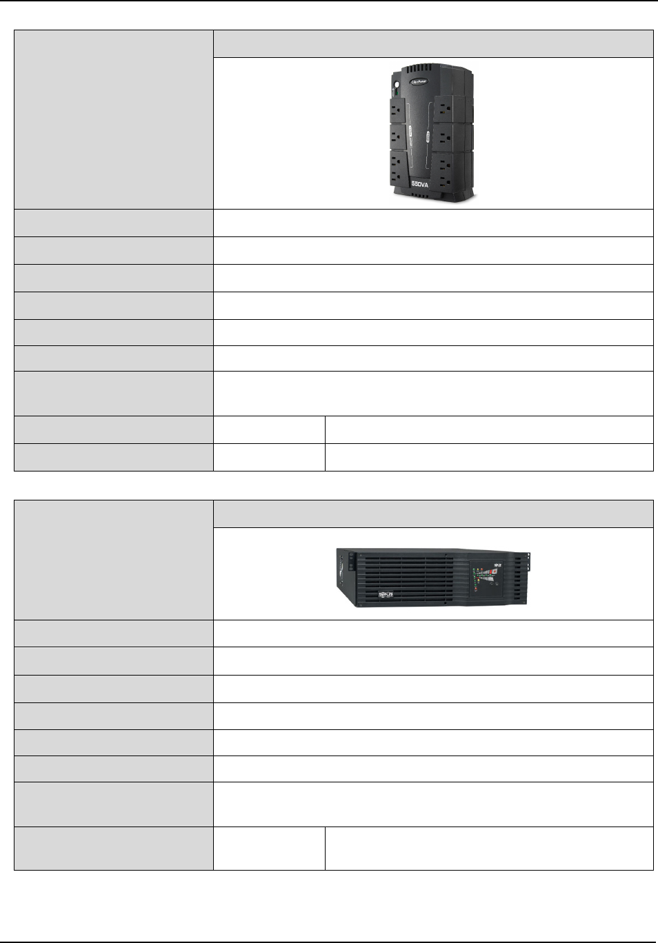
Chapter 3 – Specifications
Page 62 of 77 Quick Response Premiere Hardware Installation Guide
0510-1099-I
Universal Power
Supply
550 VAC Desktop UPS
Dimensions 9.8” L x 6.0” W x 3.0” D
Weight 6.4 lbs
Power Input
120 VAC, 60 Hz
Power Output
120 VAC, 60 Hz, 550 VA
Backup Time – 10% Signaling 15 Min
Backup Time – 100% Signaling 15 Min
Certifications FCC, Part 15
Conforms to UL Standard 1778
Part Number(s) 1000-7069 550 VAC Desktop
Additional Part Number(s) 1000-7073 750 VAC Desktop
3KVA Wired CPS UPS Kit
Dimensions
5.2” L x 17.8” W x 29.5” D
Weight
111.3 lbs
Power Input
120 VAC, 60 Hz
Power Output
120 VAC, 60 Hz, 3K VA
Backup Time – 10% Signaling 60 Min
Backup Time – 100% Signaling 30 Min
Certifications FCC, Part 15
Conforms to UL Standard 1778
Part Number(s) 1000-7079K
3KVA Wired CPS UPS Kit
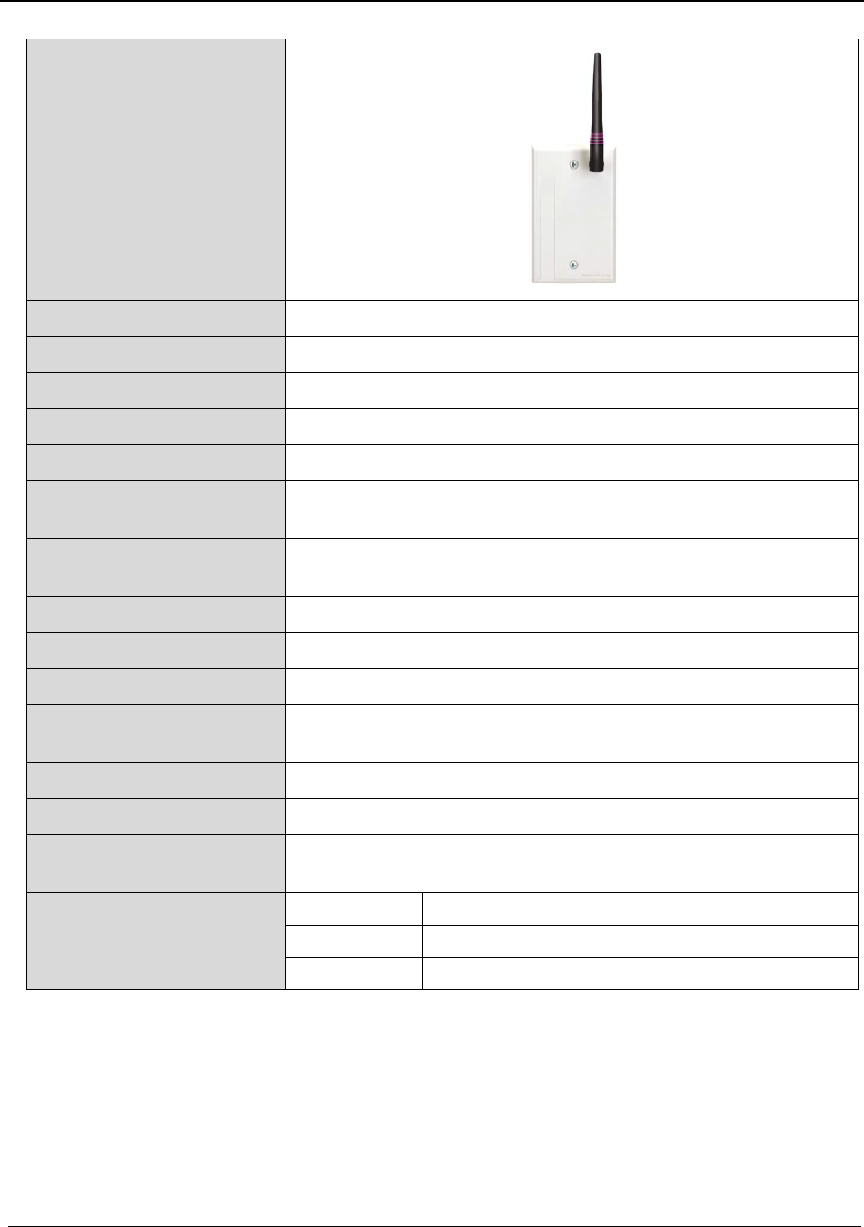
Chapter 3 – Specifications
Quick Response Premiere Hardware Installation Guide Page 63 of 77
0510-1099-I
Gateway
Dimensions 4.5" H x 2.7" W x .56" D
Weight 2.9 oz
Color Off-white
Power Requirements 9-15 VDC, 200mA UL Listed
Transmit Power
+14 dBm
Frequency Range 2.4 GHz Direct Sequence Spread Spectrum
2.405 - 2.475 GHz
Battery Backup 3.7 V, Lithium Ion Rechargeable Battery, 940 mAH Battery Backup
(10 - 12 hours) *See Note below.
Interface RS-232
Operating Temperature
0° F - 100° F
Bandwidth 5 MHz/Channel
Receive Sensitivity Received Signal, Minimum -72dBm
SNR, Minimum 9dB
Identification Number Unique, factory-programmed MAC address
Standards Zigbee 802.15.4 Compliant
Certifications FCC, Part 15
Conforms to UL Standard 1069
Part Number(s) 9600-1201 Gateway, Extended Range Whip Antenna
9600-1225K Gateway, Extended Range for Serial Terminal Server
9600-1250K Gateway, Extended Range for Serial Port

Chapter 3 – Specifications
Page 64 of 77 Quick Response Premiere Hardware Installation Guide
0510-1099-I
Router
Dimensions 4.5" H x 2.7" W x .56" D
Weight 2.9 oz
Color Off-white
Power Requirements 9-15 VDC, 200mA UL Listed
Transmit Power +14 dBm
Frequency Range 2.4 GHz Direct Sequence Spread Spectrum
2.405 - 2.475 GHz
Battery Backup 3.7 V, Lithium Ion Rechargeable Battery, 940 mAH Battery Backup
(10 - 12 hours) *See Note below.
Operating Temperature 0° F - 100° F
Bandwidth 5 MHz/Channel
Receive Sensitivity Received Signal, Minimum -72dBm
SNR, Minimum 9dB
Identification Number
Unique, factory-programmed MAC address
Standards
Zigbee 802.15.4 Compliant
Certifications FCC, Part 15
Conforms to UL Standard 1069
Part Number(s) 9600-0151 Router, Extended Range Internal Antenna
Additional Part Number(s) 9600-0160 Router, Enclosed for Outdoor Mounting
0490-0064 Plastic Outdoor Enclosure
* NOTE: Due to the limitations of the charge circuitry and the chemistry of
the backup battery contained within the Gateway/Router, it is expected
that deep discharge cycles involved in operating from the backup battery
for periods longer than 12 hours will have a detrimental effect on the life of
the battery and the maximum length of subsequent discharge cycles. It is
advisable to contact RF Technologies Technical Services for
recommendations following several deep discharge events
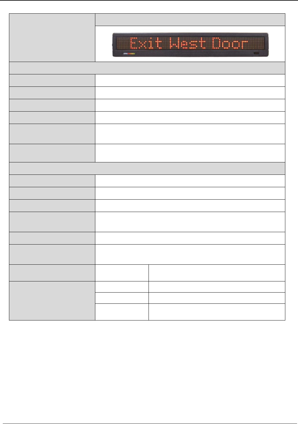
Chapter 3 – Specifications
Quick Response Premiere Hardware Installation Guide Page 65 of 77
0510-1099-I
Quick Look
Display
High Visibility
DISPLAY
Dimensions
29” L x 4.75” H x 4.5” D, with wall bracket
Weight
6.25 lbs
Color
Dark gray plastic enclosure
Voltage
120VAC Adapter Available, 60Hz
Screen LED, green, amber and red
1 line, 15 characters per line
Tilt Adjustment Reclines to maximum 180 degrees; swings forward to maximum
180 degrees
INTERFACE
Color
Off-white enclosure
Weight
1.7 oz
Power Requirements
9-15 VDC, 600mA max
Wire Requirements Category 5 (Communication)
16/2 (Power)
Standards Zigbee 802.15.4 Compliant
Certifications FCC, Part 15
Conforms to UL Standard 1069
Part Number(s) 9600-0180K High Visibility Quick Look Display & Router Kit,
Internal Antenna
Additional Part Number(s) 9450-1428K High Visibility Quick Look Display Kit
9450-1426K Safe Place High-Visibility Quick Look Interface 4.x
9450-1427K Safe Place Elopement Management High-Visibility
Display Quick Look Interface 4.x
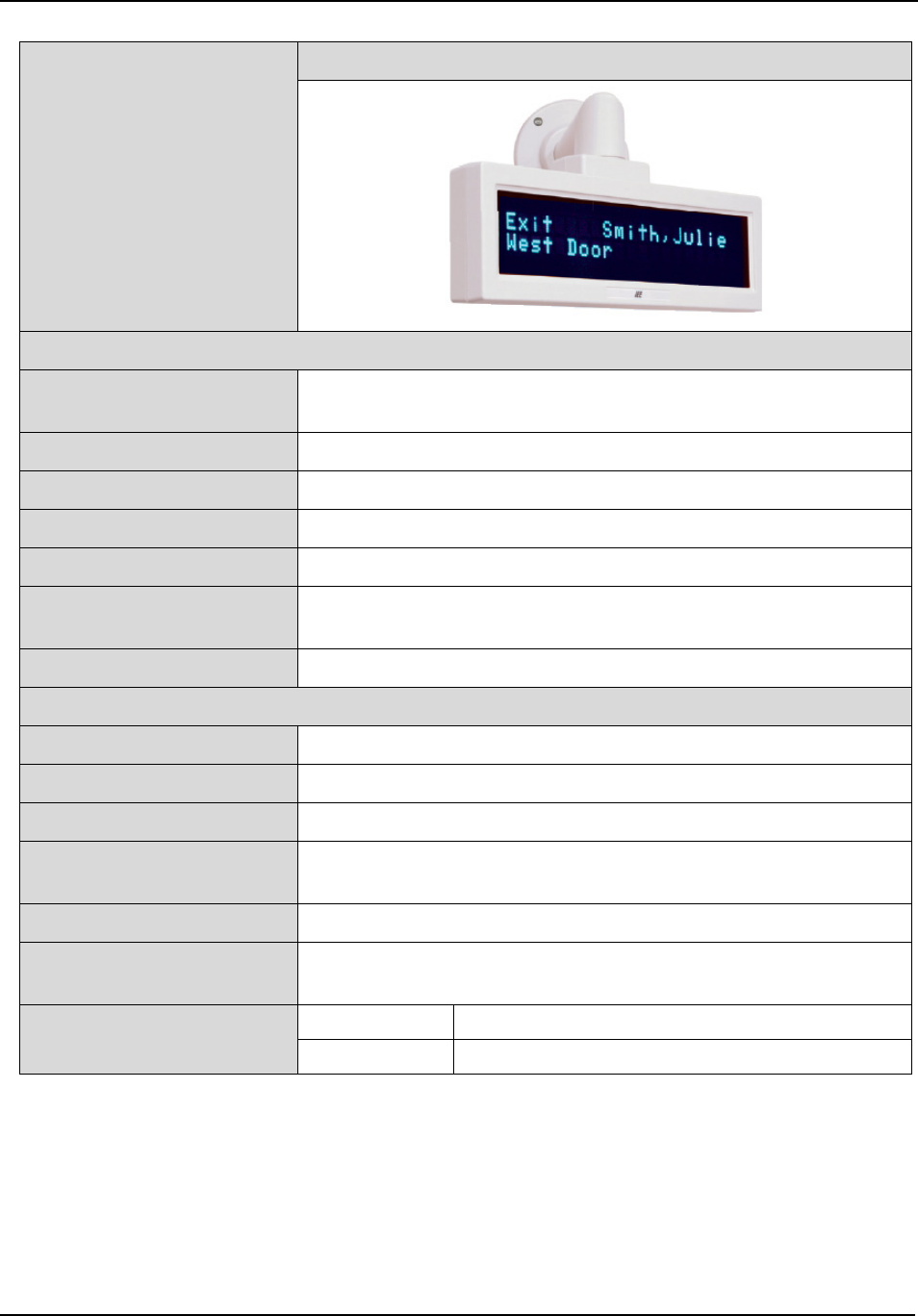
Chapter 3 – Specifications
Page 66 of 77 Quick Response Premiere Hardware Installation Guide
0510-1099-I
For Router
DISPLAY
Dimensions 11” L x 3.5” H x 2” D
Rests 3” high on wall bracket, 6” from wall
Weight 1.7 lbs
Color
Light gray plastic enclosure
Voltage 12-15 VDC
Current Consumption 400 mA for Quick Look Display w/o Router
Screen Vacuum Fluorescent (green)
2 lines, 20 Characters per line
Tilt Adjustment Reclines maximum 30 degrees; swivels a maximum 330 degrees
INTERFACE
Color Off-white plastic enclosure
Weight 1.7 oz
Power Requirements 12-15 VDC, 600 mA max with Quick Look Connected
Wire Requirements Category 5 (Communication)
16/2 (Power)
Standards
Zigbee 802.15.4 Compliant
Certifications FCC, Part 15
Conforms to UL Standard 1069
Part Number(s) 9600-0190 Quick Look with Cord Modified to Work with Router
9600-0110K Quick Look and Router Kit, Internal Antenna

Chapter 3 – Specifications
Quick Response Premiere Hardware Installation Guide Page 67 of 77
0510-1099-I
32 Channel
Controller
Dimensions 8.75" H x 6" W x 2.5" D
Weight 1.5 lbs
Color Off-white
Power Requirements 12-18 VDC, 1.75A
Maximum length from CPS is 250 ft.; Dedicated power cable from
CPS is required
Output and Wiring Contacts (30) NO 20A 24 VDC, 28-16 AWG
(3) NC/NO 2A 30 VDC, 26-12 AWG
Display
32 zone LEDs inside enclosure
Operating Temperature 0° F - 100° F
Composition ABS Flame Retardant Plastic Enclosure
Certifications FCC, Part 15
Conforms to UL Standard 1069
Part Number(s) 9600-1500 32 Channel Controller
Additional Part Number(s) 9600-0120K 32 Channel Controller with Router Kit
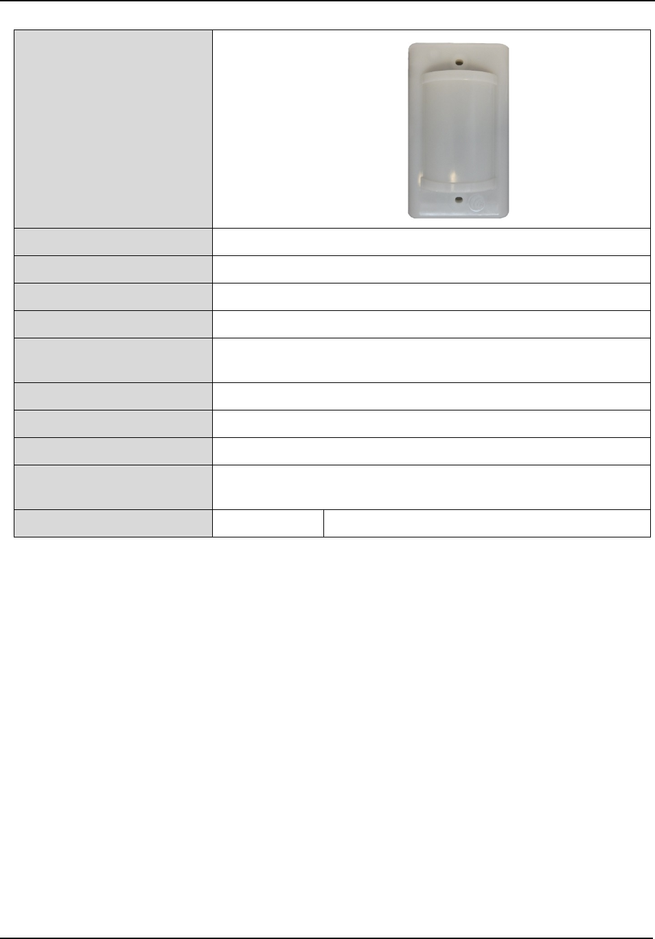
Chapter 3 – Specifications
Page 68 of 77 Quick Response Premiere Hardware Installation Guide
0510-1099-I
Dome Lights
Dimensions 4.5” L x 2.8” W x 1.25” D
Weight 3 oz
Color Translucent white lens cover
Voltage 12-24 VDC, 50mA
Wiring Power: 16 AWG 2-conductor cable
Contacts: 22 AWG 2-conductor cable
Input Contacts
One set per circuit, selectable NO or NC
Lamps
One white lamp (“normal” alarm); One red lamp (“emergency” alarm)
Operating Temperature 32-104°F
Certifications Conforms to UL Standard 1069
Certified To CSA STD C22.2 # 205
Part Number(s) 9600-0295 180 Degree Dome Light for Wireless Systems
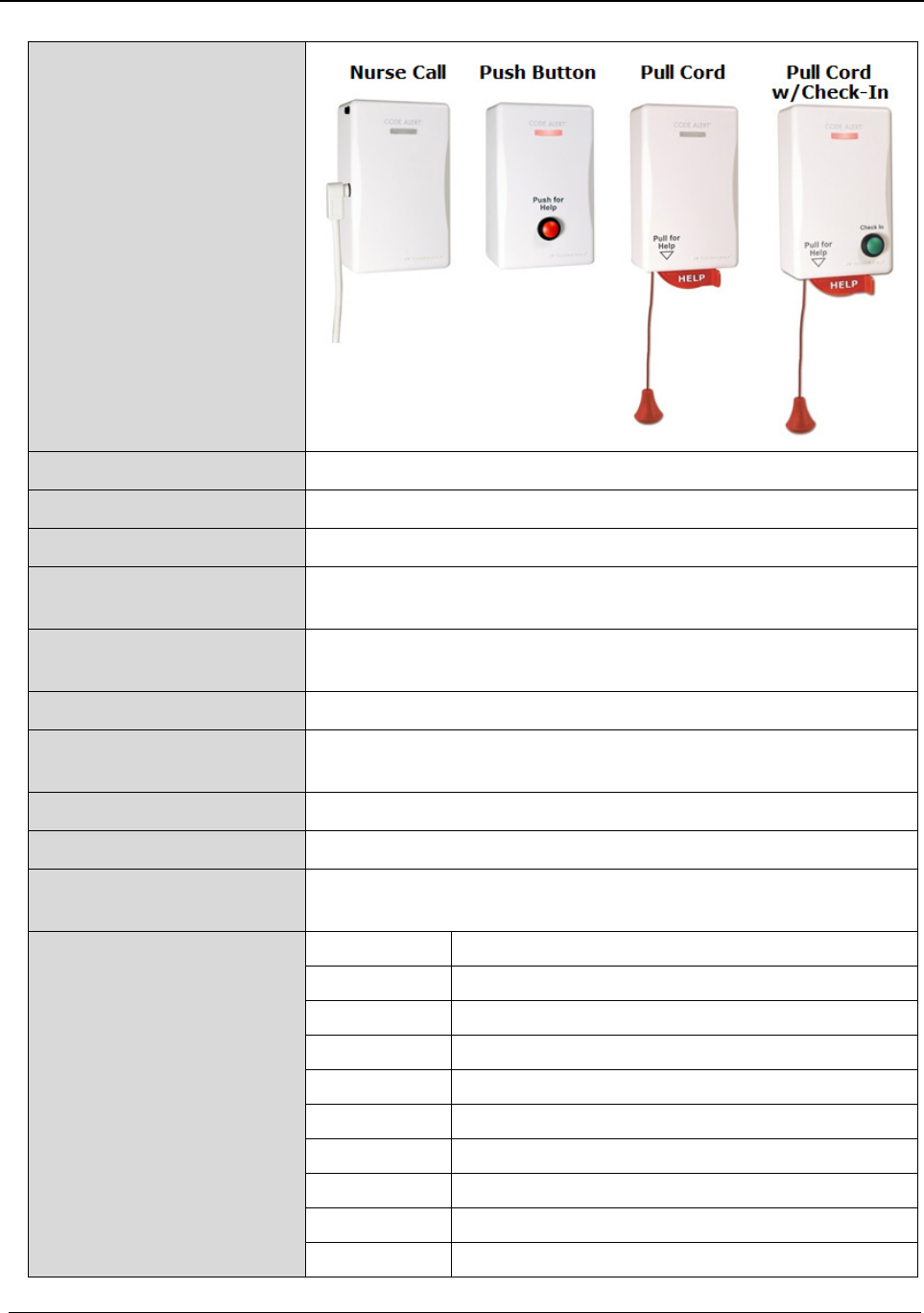
Chapter 3 – Specifications
Quick Response Premiere Hardware Installation Guide Page 69 of 77
0510-1099-I
Call Stations
Dimensions
4.8" H x 3.0" W x 1.6" D
Weight
2.9 oz
Color
Off-white
Power Requirements (4) AA lithium batteries
3 - 4 years typical battery life, depending on use
Frequency 2.4 GHz Direct Sequence Spread Spectrum
2.405 - 2.475 GHz
Transmit Power 0 dBm
Receive Sensitivity Received Signal, Minimum -72dBm
SNR, Minimum 9dB
Operating Temperature 0-110°F
Standards Zigbee 802.15.4 Compliant
Certifications FCC, Part 15
Conforms to UL Standard 1069
Part Number(s) 9600-0305 Pull Cord Station
9600-0355 Pull Cord Station with Check-In
9600-0377 Push Button Station
9600-0380 Wireless Nurse Call Jack
9600-0388 Nurse Call Jack Station with Reset
0490-0501 Nurse Call Cord Set, Single Station, 10 ft. Locking Button
0490-0502 Nurse Call Cord Set, Double Station, 10 ft. Locking Button
0490-0505 Nurse Call, Touch Activated
0490-0538 Nurse Call Cord Set, Single Station, 10 ft. Momentary
0490-0549 Nurse Call Cord Set, Single Station, 10 ft. Momentary UL
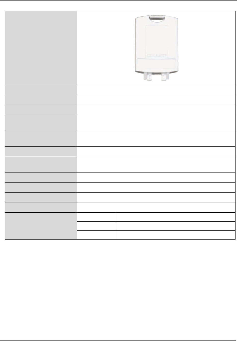
Chapter 3 – Specifications
Page 70 of 77 Quick Response Premiere Hardware Installation Guide
0510-1099-I
Universal
Transceiver
Dimensions
2.2" H x 1.8" W x 8" D
Weight
.64 oz
Color
Off-white
Power Requirements 3.0V Coin Cell Lithium Battery, CR 2450
2 year battery life
Frequency 2.4 GHz Direct Sequence Spread Spectrum
2.405 - 2.475 GHz
Transmit Power
0 dBm
Receive Sensitivity Received Signal, Minimum -72dBm
SNR, Minimum 9dB
Operating Temperature 0-110°F
Identification Number Unique, factory-programmed MAC address
Standards Zigbee 802.15.4 Compliant
Certifications FCC, Part 15
Part Number(s) 9600-1406 Universal Transceiver with (3) 12” Wires
9600-1422 Universal Transceiver with 48” Wires
9600-1442 Universal Transceiver with (2) 12” Wires
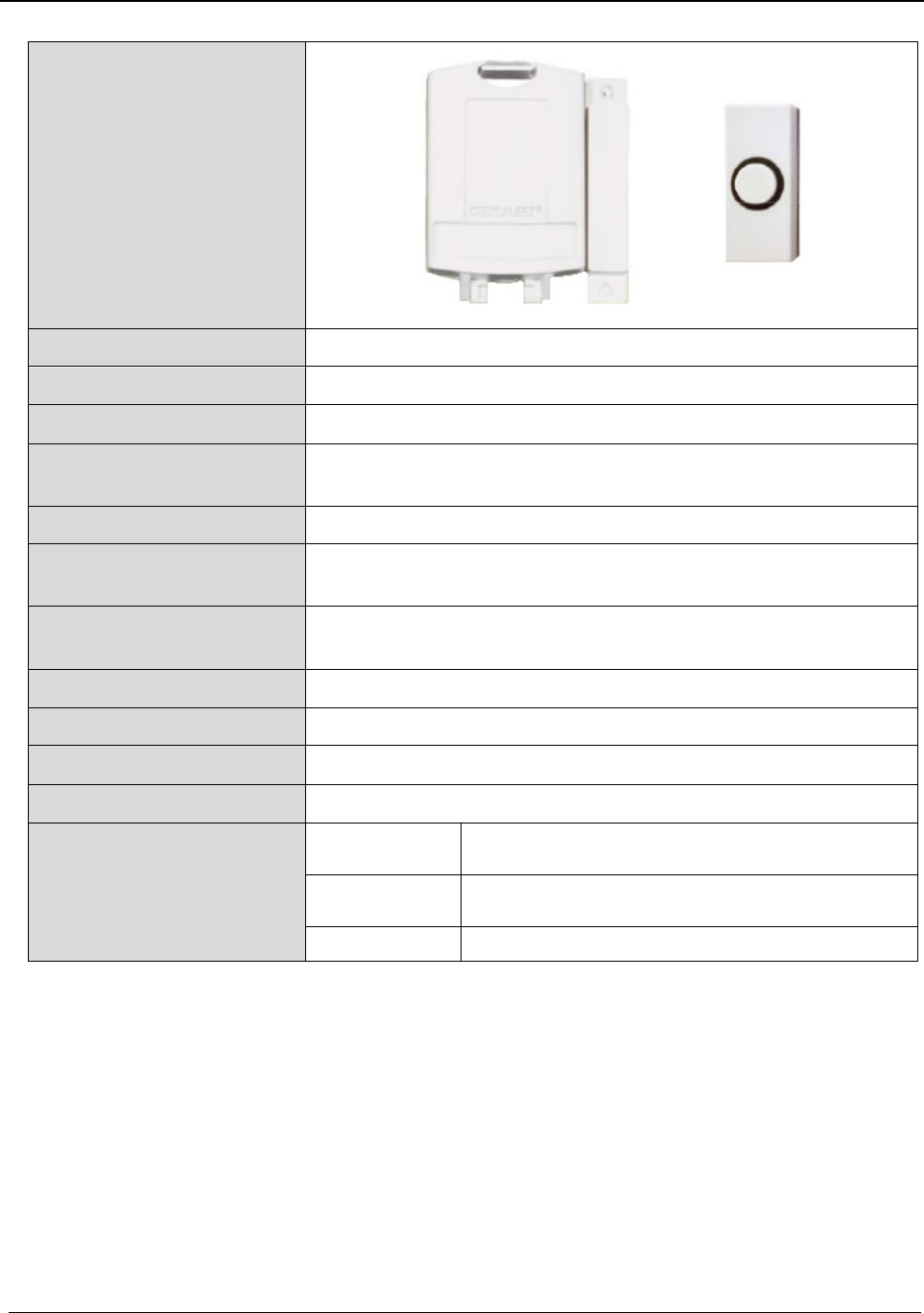
Chapter 3 – Specifications
Quick Response Premiere Hardware Installation Guide Page 71 of 77
0510-1099-I
Door/Window
Transceiver
Dimensions 2.2" H x 1.8" W x 8" D
Weight .68 oz
Color Off-white
Power Requirements 3.0V Coin Cell Lithium Battery, CR 2450
2 year battery life
Frequency
0 dBm
Transmit Power 2.4 GHz Direct Sequence Spread Spectrum
2.405 - 2.475 GHz
Receive Sensitivity Received Signal, Minimum -72dBm
SNR, Minimum 9dB
Operating Temperature
0-110°F
Identification Number
Unique, factory-programmed MAC address
Standards
Zigbee 802.15.4 Compliant
Certifications
FCC, Part 15
Part Number(s) 9600-1452K Universal Transceiver with 48” Wires, Reset Button,
Surface Mount
9600-1457K Universal Transceiver with 48” Wires, Reset Button,
Flush Mount
9600-1462K Universal Transceiver Door and Window Kit

Chapter 3 – Specifications
Page 72 of 77 Quick Response Premiere Hardware Installation Guide
0510-1099-I
Pendant
Dimensions 2.13" H x 1.34" W x .64" D (5.41 cm x 3.40 cm x 1.62 cm)
Weight 1.4 oz
Color Off White Pendant with Blue Protective Boot
Power Requirements 3.0V Coin Cell Lithium Battery, CR 2450 or CR 2032
Up to 3 years if at 24 hr supervision
Bandwidth
+9 dBm
Frequency
5 MHz/Channel
Transmit Power 2.4 GHz Direct Sequence Spread Spectrum
2.405 - 2.475 GHz
Receive Sensitivity Received Signal, Minimum -72dBm
SNR, Minimum 9dB
Operating Temperature
0-110°F
Protective Boot
Latex-Free Silicon
Options Lanyard, wristband (black or blue) or breakaway necklace
Identification Number
Unique, factory-programmed MAC address
Standards
Zigbee 802.15.4 Compliant
Certifications FCC, Part 15
Conforms to UL Standard 1069
Part Number(s) 9600-0251 Call Pendant
Additional Part Number(s) 0160-0036K Protective Boot and Black Nylon Wristband Kit for Call
Pendant
0160-0036 Black Nylon Wristband, Buckle Closure
0220-0203 Protective Boot
0490-0039 Plastic Necklace
0160-0025 Blue Wristband, Velcro
®
Closure
0490-0507 Lanyard Necklace with Breakaway Connector and Hook
0770-0014 Lanyard, Clear, with Clip and Breakaway Necklace
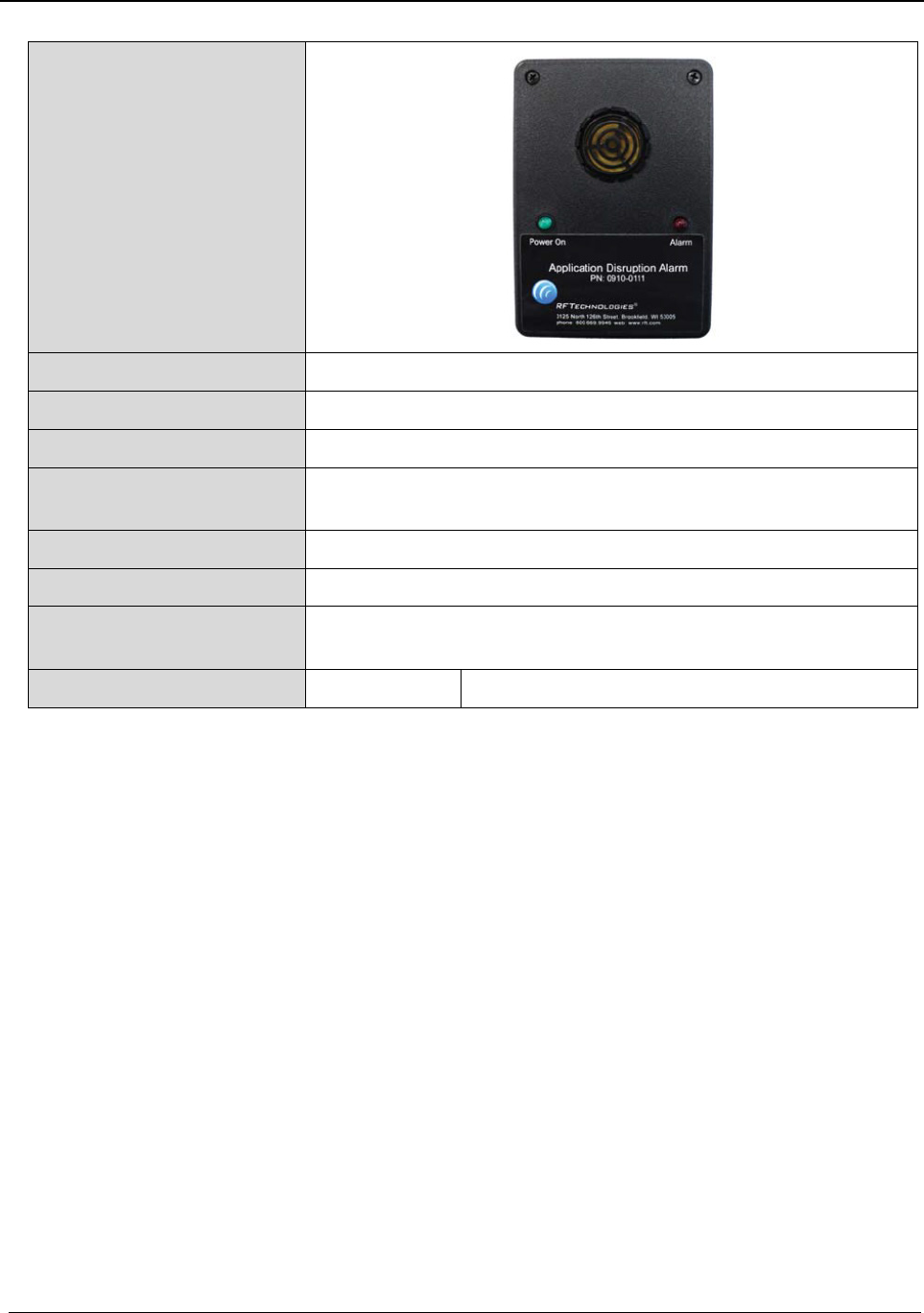
Chapter 3 – Specifications
Quick Response Premiere Hardware Installation Guide Page 73 of 77
0510-1099-I
Application
Disruption Alarm
Dimensions
4.5” L x 3.1” W x 1.8” D
Weight
5 oz
Power Requirements
5 VDC @ 1A
LED Notifications Green LED: Indicates proper device operation
Red LED: Indicates a trouble condition when illuminated
Operating Temperature 32-104°F
Enclosure Black ABS
Certifications FCC, Part 15
Conforms to UL Standard 1069
Part Number(s)
9600-1085 Application Disruption Alarm
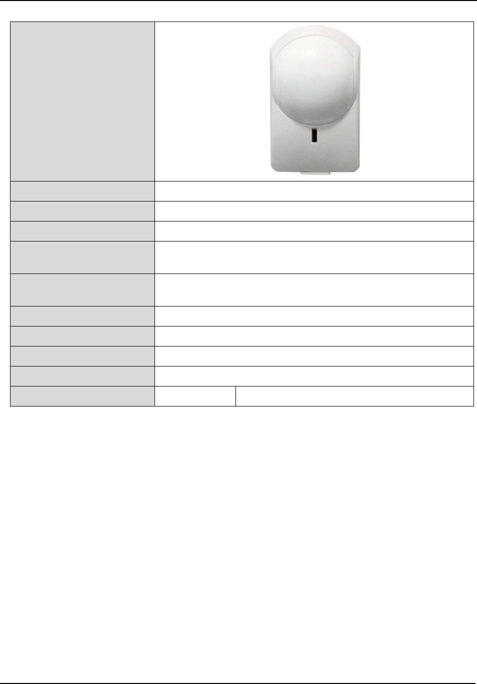
Chapter 3 – Specifications
Page 74 of 77 Quick Response Premiere Hardware Installation Guide
0510-1099-I
PIR Motion Sensor
Dimensions 4.38” L x 2.38” W x 3” D
Weight 0.4 lbs
Color Off-white
Power Requirements 3 V lithium battery
Up to two years battery life, depending on use
Transmit Power 2.4 GHz direct sequence spread spectrum
2.405-2.475 GHz
Frequency 0 dBm
Identification Number Factory-programmed MAC address
Standards IEEE 802.15.4, ZigBee®-compliant
Certifications FCC, Part 15
Part Number(s) 9600-0606 Motion Sensor (PIR)

Chapter 3 – Specifications
Quick Response Premiere Hardware Installation Guide Page 75 of 77
0510-1099-I
Smoke Detector
Dimensions
5.5” diameter, 2.5” deep
Weight
0.6 lbs
Color
Off-white
Power Requirements
120 VAC
Transmit Power
0 dBm
Frequency 2.4 GHz direct sequence spread spectrum
2.405-2.480 GHz
Identification Number Unique, factory-programmed MAC address
Standards IEEE 802.15.4, ZigBee®-compliant
Certifications FCC, Part 15
Conforms to UL Standard 1069
Part Number(s) 9600-1426 Battery Powered Smoke Detector
9600-1471K 120 VAC Smoke Detector

Chapter 3 – Specifications
Page 76 of 77 Quick Response Premiere Hardware Installation Guide
0510-1099-I
Carbon Monoxide
Alarm
Dimensions 6.0” L x 2.7” W x 1.35” D
Weight 4 oz
Color White
Power Requirements 12VDC
CO Alarm Level 70ppm or higher
Sounder 85 dB
Operating Temperature 40-100°F. 15-90% Relative humidity, non-condensing
Standards IEEE 802.15.4, ZigBee®-compliant
Certifications Conforms to UL Standard 2075
CSFM
Part Number(s) 9600-1476K QR Premiere, Carbon Monoxide Alarm

Revision History
Quick Response Premiere Hardware Installation Guide Page 77 of 77
0510-1099-I
Revision History
Revision Change
A Release
B Updated: Dome Light PCB figure
C Updated: Document to satisfy UL 1069 requirements
D Updated: Wording in French Compliance section per the FCC review
E Added: System to be professionally installed per the FCC review
F Updated: Document to latest format
Updated: “To wire Dome Lights to the 32 Channel Controller” section for clarification on the
contacts
Updated: Specifications section
G Updated: Quick Look Specifications
H Added: Instructions to the Mounting Call Stations section for installing retention hardware
on the nurse call cords
Added: Carbon Monoxide Alarm instructions (previously in 0510-0321)
Updated: Dome Light specifications for new lens
Updated: Part numbers listed in the FCC Radiation Exposure Statement for Portable
Devices
I Updated: French translations for the “Radiation Exposure Statement for Mobile Devices”
and “Radiation Exposure Statement for Portable Devices” sections