R F Technologies SPFSZ24 Help Alert Pendant User Manual 9450UserGuide
R F Technologies Inc Help Alert Pendant 9450UserGuide
Contents
- 1. User Manual 1
- 2. User Manual 2
User Manual 2

Series 6.0 Software (0510-1065-A) - User Guide 71
Chapter 4
Handling Events
Introduction
This chapter provides information about the Events. It provides a detail description of alarming events, the devices
that triggered the events and information about responding to the specific events.
Events
An event is an action that occurs in the software that requires a response from an authorized user. When an event
occurs, a message is displayed in the Event List indicating the relevant device, the patient’s or asset’s name when
applicable, and the type of event received.
Click anywhere in the Alarm Message Box to access more information about the event and to select a cause for the
event, if applicable, from the Event Information window. These event causes are then logged into the applicable
reports. For information about reporting, see Chapter 5, Using System Reports.
WARNING: The Series 6.0 Software is designed and intended to work in
conjunction with a facility’s overall patient security program, including reasonable
operating policies and procedures. The Series 6.0 Software, by itself, cannot
prevent abductions or elopements.
Chapter 4: Handling Events
72 Series 6.0 Software (0510-1065-A) - User Guide
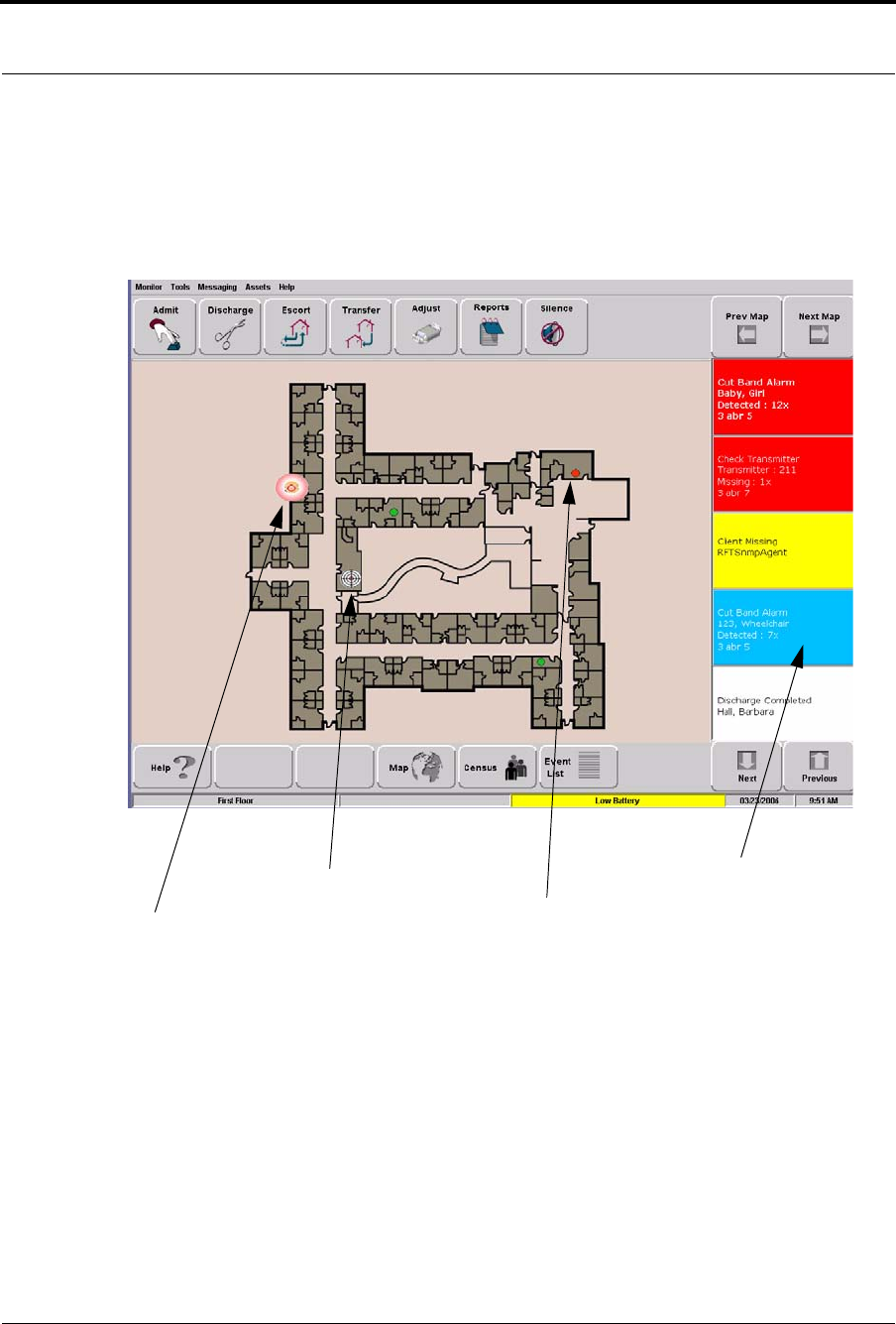
Devices Displayed on the Map
Devices are displayed on the map or floor plan on the Client computer(s). The display is configured to assist the
staff in monitoring devices. The location of a device issuing an alarm is indicated by a flashing icon on the map.
FIGURE 4.1: Main Window
Alarm Message Box
Flashing icon indicates the location
You are here
Room device in alarm
(location of client computer)
of the device reporting the event
Series 6.0 Software (0510-1065-A) - User Guide 73
Events
Devices Assigned to a Room
Devices assigned to a room will not show on the map until the room device goes into alarm. The map will display
the room to which the alarming device is assigned. By clicking on the alarming device icon, you can bring up
details of the alarm. If more than one device is assigned to a room, details on both devices are displayed. Click OK
to dismiss the alarm. The icon will continue to flash until the alarm is cleared.
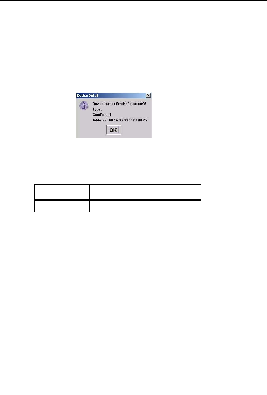
FIGURE 4.2: Room Detail Window
If a transmitter location changes, for example if an alarm is activated while the transmitter is in motion, the Router
closest to the transmitter triggers the alarm. The icon representing the Router flashes on the Client computer map.
Below is a table of how devices are displayed on the map in the Main Window.
Normal Mode Alarming Device Fault
Green Flashing Red Flashing Yellow
Chapter 4: Handling Events
74 Series 6.0 Software (0510-1065-A) - User Guide
Event Types
There are several different event types that can occur when using the Series 6.0 Software. The following sections
provide a brief overview of each event as well as an action to take if this event occurs.
Event Information Window
When an event occurs, an Alarm Message Box is displayed in the Event List. Click anywhere in the Alarm
Message Box to access the Event Information window. The Event Information window contains detailed
information about the event. If a picture is available, certain events will display the picture of the patient or asset
associated with the event.
Selecting an Event Cause will clear an alarm.
FIGURE 4.3: Event Information Window
WARNING: If you do not already have procedures in place, you must
establish procedures for your staff to follow to ensure patient safety and
to secure the area in the event of an alarm. Existing procedures may
require modification to incorporate optional features. Failure to create or
modify these procedures may result in patient abduction or elopement.
NOTE: The Event Cause buttons in the Event Information window are different for each
event. See the following sections for detailed information.
Event Cause
Buttons

Series 6.0 Software (0510-1065-A) - User Guide 75
Event Types
Event Information Window Properties
The following table provides brief descriptions of the properties that appear in the Event Information window.
Event—Lists the type of event recorded.
Time—Shows the time that the event occurred.
Patient
Name—the transmitter ID number, or the name of the patient or asset to whom the transmitter is assigned.
Room—the room number of the patient or asset.
Unit—the unit that the patient or asset is assigned to.
Gender—the gender of the patient.
Risk—the risk level assigned to the patient or asset.
Admitted By—the staff member who performed the admission.
Transmitter—the identification number of the transmitter that initiated the event.
Type—the type of transmitter that sent the signal.
Device Location
Device Name—the name of the device that received the alarm.
Device Type—the type of device that received the alarm.
Help—displays help information for the Event Information window.
Review Print Info—opens an Event Information Report with patient or asset, event and device location
information.
Close— closes the Event Information window without clearing the alarm.

Chapter 4: Handling Events
76 Series 6.0 Software (0510-1065-A) - User Guide
Red Alarms
The following sections provide detailed information about Red Alarms, responding to alarming events, and the
the way the event should be cleared. Red Alarms are high priority alarms. They are displayed in the Alarm
Message Box and the Event List sequentially as they occur. Red Alarms are displayed first in the Alarm Message
Box and Event list.
Door Alarm
When a patient wearing an alarming band transmitter is in an Exit Alarm Zone and the monitored door is open,
an alarm sounds at the Exit Alarm Controller, a message is displayed on the Client computer(s) in the unit
configured to monitor the transmitter, and the location of the Exit Alarm Zone is indicated by a flashing icon on
the map on the Client computer(s). Door Alarms are also displayed on remote notification devices.
To respond to a Door Alarm
1. Always follow your facility’s policies and procedure to ensure patient safety and secure the area.
2. Go to the alarming device and use your card reader access card (if applicable) or enter the appropriate 4-
digit alarm code to clear the alarm at the device. For more information about the Alarm Code, contact
your System Administrator.
3. If the Enforce JCAHO feature is activated, you must select an Event Cause once the alarming device
has been reset. When you reset the alarming device, the Red Alarm changes to a White Alarm in the
Alarm Message Box and Event List. If JCAHO is not activated, the Alarm Message Box clears once the
alarm is cleared at the device.
4. From the Client computer, click anywhere in the Door Alarm Message Box to access the Event
Information window.
5. Select one of the following causes for the Door Alarm:
•Escort problem—there was an issue while the patient was in escort.
•Tr a n s f er p r o b l e m —there was an issue while the patient was in transfer.
•Accidentally close to open door—the patient was near a door when it was opened.
•Noise —there were noise issues with the device.
•Te s t —the system was being tested.
•Other—opens a Clear Reason window, user must enter the cause in this window.
You cannot clear an event until you select the appropriate cause for the event. The event is cleared from
the Event List of every Client computer configured to monitor the unit.
NOTE: You can click Silence to stop the alarm sound at the Central Server or Client
computer. The alarm is silenced at that computer only, for the configured length of time;
however, the event still appears in the Event List. The next event automatically restarts the
alarm sound.

Series 6.0 Software (0510-1065-A) - User Guide 77
Event Types
Exit Alarm (Wide Gap)
A Wide Gap Exit Alarm occurs when a door or window monitored by a Door/Window transmitter is opened. A
Door/Window transmitter is a device that protects a door or window against unauthorized egress. When a Wide
Gap Exit Alarm occurs, a message is displayed on the Client computer(s) in the unit configured to monitor the
door or window, and the location of the Exit Alarm is indicated by a flashing icon on the map on the Client
computer(s).
To respond to a Wide Gap Exit Alarm
1. Always follow your facility’s policies and procedures to ensure patient safety and secure the area.
2. Locate the door or window that initiated the alarm.
3. Close the door or window. The system records the event and clears the alarm when the door or window
is closed.
Smoke Alarm
When a smoke detector that is integrated with the system is activated, an alarm sounds, a message is displayed on
the Client computer(s) in the unit configured to monitor the device, and the location of the Smoke Alarm is
indicated by a flashing icon on the map on the Client computer(s). An event is reported in the Event List each
time the smoke detector is activated.
To respond to a Smoke Alarm
1. Always follow your facility’s policies and procedures to ensure patient safety and secure the area.
2. Locate the alarming device. Smoke Alarms must be reset at the alarming device.The system records the
event as a Reset when the smoke detector is reset.
NOTE: No local audible alarms are sounded from the Door/Window transmitter when an
alarm occurs.
NOTE: You can click Silence to stop the alarm sound at the Central Server or Client
computer. The alarm is silenced at that computer only, for the configured length of time;
however, the event still appears in the Event List. The next event automatically restarts the
alarm sound.

Chapter 4: Handling Events
78 Series 6.0 Software (0510-1065-A) - User Guide
Perimeter Alarm
A Perimeter Alarm occurs when the doors monitored by the system are in Perimeter mode and a door is opened.
Perimeter mode is when a door is in a lockdown state as a result of system configuration or an event. Perimeter
mode also occurs when a door is open at the time a Cut Band Alarm occurs.
When a Perimeter alarm occurs, an alarm sounds at the Exit Alarm Controller, a message is displayed on the
Central Server or Client computer(s) in the unit configured to monitor the door, and the location of the Exit
Alarm is indicated by a flashing icon on the map on the Client computer(s).
To respond to a Perimeter Alarm
1. Always follow your facility’s policies and procedures to ensure patient safety and secure the area.
2. Locate the alarming device. Perimeter Alarms must be reset at the alarming device.
3. Go to the Exit Alarm Controller and use your card reader access card (if applicable) or enter the
appropriate 4-digit alarm code. For more information about the Alarm Code, contact your System
Administrator. The system records the event as a Reset when the appropriate code is entered.
4. If the Enforce JCAHO feature is activated, you must select an Event Cause once the alarming device
has been reset. When you reset the alarming device, the Red Alarm changes to a White Alarm in the
Alarm Message Box and Event List. If JCAHO is not activated, the Alarm Message Box clears once the
alarm is cleared at the device.
5. From the Central Server or Client computer, click anywhere in the Perimeter Alarm Message Box to
access the Event Information window.
6. Select one of the following causes for the Perimeter Alarm:
•Escort problem—there was an issue while the patient was in escort.
•Tr a n s f er p r o b l e m —there was an issue while the patient was in transfer.
•Accidentally close to open door—the patient was near a door when it was opened.
•Noise —there were noise issues with the device.
•Te s t —the system was being tested.
•Other—opens a Clear Reason window, user must enter the cause in this window.
You cannot clear an event until you select the appropriate cause for the event. The event is cleared from
the Event List of every Client computer configured to monitor the unit.
NOTE: You cannot silence or reset the Exit Alarm Controller’s alarms from the Central
Server and Client computer(s). You must reset the alarm at the Exit Alarm Controller.
NOTE: Any perimeter alarms that occur due to a door open during a Cut Band Alarm
require that the Cut Band Alarm be cleared at the computer first, before the doors are reset
or cleared.
NOTE: You can click Silence to stop the alarm sound at the Central Server or Client
computer. The alarm is silenced at that computer only, for the configured length of time;
however, the event still appears in the Event List. The next event automatically restarts the
alarm sound.

Series 6.0 Software (0510-1065-A) - User Guide 79
Event Types
Cut Band Alarm
When the banding material on a patient’s alarming band transmitter is cut, tampered with or opened without
authorization (which includes opening the transmitter when a timed event has expired), an alarm is sounded on
the computer configured to monitor the unit, a message is displayed in the Event List, and the location of the
Alarming Band Receiver that detected the event is indicated on the map on the computer(s). Cut Band Alarms
are also displayed on remote notification devices.
If your facility has enabled the Lockdown on Cut Band Alarms feature, a Cut Band Alarm will trigger a Global
Lockdown.You can configure the Global Lockdown feature to lock doors at All exits or By transmitter units.
However if a Cut Band Alarm is initiated during an Escort or a Transfer, the system automatically locks All exits
since the transmitter in Escort or Transfer may be outside of its protected unit and displays the alarm on all Client
computers and Quick Look displays.
To respond to a Cut Band Alarm
1. Always follow your facility’s policies and procedures to ensure patient safety and secure the area.
2. Verify the transmitter is applied correctly and without signs of damage or tampering.
3. From the Client computer, click anywhere in the Cut Band Alarm Message Box to access the Event
Information window.
4. Select one of the following event causes:
•Clasp open —one of the clasps on the transmitter was open.
•Band cut—the banding material on the transmitter was cut.
•Band worn—the banding material on the transmitter is worn and must be replaced.
•Unauthorized open-—an unauthorized person opened the transmitter clasp.
•Adjust—a transmitter was being adjusted without authorization, an adjust was not requested or
an adjust occurred after the adjust time expired.
•Discharged —the transmitter was being removed in a discharge without authorization, a
discharge was not requested or a discharge occurred after the adjust time allowed.
•Te s t —the system was being tested.
•Other—opens a Clear Reason window, user must enter the cause in this window.
You cannot clear an event until you select the appropriate cause for the event. The event is cleared from
the Event List of every Client computer configured to monitor the unit.
NOTE: Any perimeter alarms that occur due to a door open during a Cut Band Alarm
require that the Cut Band Alarm be cleared at the computer first, before the doors are reset
or cleared.
NOTE: You can click Silence to stop the alarm sound at the Central Server or Client
computer. The alarm is silenced at that computer only, for the configured length of time;
however, the event still appears in the Event List. The next event automatically restarts the
alarm sound.

Chapter 4: Handling Events
80 Series 6.0 Software (0510-1065-A) - User Guide
Mismatch Alarm
A Mismatch alarm occurs if an Infant transmitter is located within proximity of a Mother transmitter that is
linked to a different transmitter.
To respond to a Mismatch Alarm
1. Always follow your facility’s policies and procedures to ensure patient safety and secure the area.
2. Click anywhere in the message box to access the Event Properties window.
3. Select one of the following Event reasons:
•No problem—no issue was found.
•Wrong Infan t—the Infant Transmitter is linked with the wrong Mother Transmitter.
•Mothers bonding—while two mothers were socializing, one of the Mother Transmitters picked
up the other Mother’s Infant Transmitter signal.
•Infant not present—an Infant Transmitter was not present.
•Te s t —the system was being tested.
•Other—opens a Clear Reason window, user must enter the cause in this window.
You cannot clear an event until you select the appropriate cause for the event. The event is cleared from
the Event List of every Client computer configured to monitor the unit.
Match Alarm
You can configure the system to require a Mother/Infant match before an infant can be discharged. The Match
Alarm occurs when an infant is discharged and the alarming band material is cut, before performing the required
Mother/Infant match. The Require Mother/Infant match before discharge is configured in the Configuration,
Global Settings menu (refer to the Series 6.0 Software Administrator Guide).
To respond to a Match Alarm
1. Always follow your facility’s policies and procedures to ensure patient safety and secure the area.
2. Click anywhere in the Match Alarm Message Box to access the Event Information window.
3. Click Clear.
If necessary, perform the discharge function again by first performing the Mother/Infant match.
NOTE: You can click Silence to stop the alarm sound at the Central Server or Client
computer. The alarm is silenced at that computer only, for the configured length of time;
however, the event still appears in the Event List. The next event automatically restarts the
alarm sound.

Series 6.0 Software (0510-1065-A) - User Guide 81
Event Types
Link Alarm
This alarm occurs when there is a problem linking the Infant transmitter to a Mother transmitter. For example,
the Infant transmitter may already be linked to another Mother transmitter.
To respond to a Link Alarm
1. Always follow your facility’s policies and procedures to ensure patient safety and secure the area.
2. Click anywhere in the Link Alarm Message Box to access the Event Information window.
3. Click Clear.
4. If necessary, verify the identity of the mother and infant then relink the Mother and Infant transmitters.
Check Alarm (not “Check Transmitter Alarm”)
No message has been received from the patient’s transmitter or the device in the patient’s room during the
Inactivity Check-In period. The Check message will remain until the patient’s transmitter checks in, an Alarm
message is received, or the event is manually cleared at the Client computer(s).
To respond to a Check Alarm
1. Always follow your facility’s policies and procedures to ensure patient safety and secure the area.
2. Locate the device.
3. Verify that no patient emergency exists.
4. From the Client computer, click anywhere in the Inactivity Check-In Alarm Message Box to access the
Event Information window.
5. Select Clear to clear the Inactivity Check-In alarm.
NOTE: You can click Silence to stop the alarm sound at the Central Server or Client
computer. The alarm is silenced at that computer only, for the configured length of time;
however, the event still appears in the Event List. The next event automatically restarts the
alarm sound.

Chapter 4: Handling Events
82 Series 6.0 Software (0510-1065-A) - User Guide
Check Transmitter Alarm
A Check Transmitter alarm occurs when the system is unable to locate the transmitter within the required
supervised time.
To respond to a Check Transmitter Alarm
1. Always follow your facility’s policies and procedures to ensure patient safety and secure the area.
2. Verify transmitter is fastened correctly and without signs of damage.
For more information, refer to the appropriate Transmitter User Guide.
3. From the Client computer, click anywhere in the Check Transmitter Alarm Message Box to access the
Event Information window.
4. Select one of the following event causes:
•Clasp open —one of the clasps on the transmitter was open.
•Band cut—the banding material on the transmitter was cut.
•Band worn—the banding material on the transmitter is worn and must be replaced.
•Unauthorized open-—an unauthorized person opened the transmitter clasp.
•Adjust—a transmitter was being adjusted without authorization.
•Discharged —the transmitter was being removed in a discharge without authorization.
•Te s t —the system was being tested.
•Other—opens a Clear Reason window, user must enter the cause in this window.
You cannot clear an event until you select the appropriate cause for the event. The event is cleared from
the Event List of every Client computer configured to monitor the unit.
5. A Check Transmitter alarm may be an indication that Receiver coverage may be inadequate. Contact
your System Administrator.
WARNING: You must test all transmitters prior to use, and periodically
thereafter, to verify proper operation. Failure to test the transmitters before use
can result in system failure and/or an elopement or abduction. In addition, failure
to test transmitters voids the RF Technologies Product Warranty.
NOTE: You can click Silence to stop the alarm sound at the Central Server or Client
computer. The alarm is silenced at that computer only, for the configured length of time;
however, the event still appears in the Event List. The next event automatically restarts the
alarm sound.

Series 6.0 Software (0510-1065-A) - User Guide 83
Event Types
Assistance Required
An Assistance Required alarm occurs when a QR device belonging to a patient alarms. The Alarm message will
remain until the alarming device is reset. An Assistance Required alarm is also activated in response to a Fall
Management System alert.
To respond to an Assistance Required Alarm
1. Always follow your facility’s policies and procedures to ensure patient safety and secure the area.
2. Locate the alarming device. Assistance Required Alarms must be reset at the alarming device.
3. Reset the alarming device. The system records the event as a Reset when the alarming device is reset.
4. If responding to a Fall Management System alert, the system will automatically reset and begin
monitoring once the patient is placed back on the Sensor Pad (refer to “Messaging Services” on
page 26).
5. If the Enforce JCAHO feature is activated, you must select an Event Cause once the alarming device
has been reset. When you reset the alarming device, the Red Alarm changes to a White Alarm in the
Alarm Message Box and Event List. If JCAHO is not activated, the Alarm Message Box clears once the
alarm is cleared at the device.
6. From the Client computer, click anywhere in the Assistance Required Alarm Message Box to access the
Event Information window.
7. Select one of the following event causes:
•Fall —the patient had fallen and needed assistance.
•Water—the patient required water.
•Food—the patient required food.
•Talk-—the patient had matters to discuss with the attendant.
•Bathroom—the patient required bathroom assistance.
•Te s t —the system was being tested.
•Other—opens a Clear Reason window, user must enter the cause in this window.
You cannot clear an event until you select the appropriate cause for the event. The event is cleared from
the Event List of every Client computer configured to monitor the unit.
NOTE: You can click Silence to stop the alarm sound at the Central Server or Client
computer. The alarm is silenced at that computer only, for the configured length of time;
however, the event still appears in the Event List. The next event automatically restarts the
alarm sound.

Chapter 4: Handling Events
84 Series 6.0 Software (0510-1065-A) - User Guide
Fall Alarm
This alarm occurs when a patient removes his/her weight from the sensor pad. The alarm clears when weight is re-
applied to the pad. The Alarm Message Box will remain on the Client computer until the alarming device is reset.
To respond to an Fall Alarm
1. Always follow your facility’s policies and procedures to ensure patient safety and secure the area.
2. Secure the patient from a potential fall situation.
3. The system will automatically reset and begin monitoring once the patient is placed back on the Sensor
Pad.
4. If the Enforce JCAHO feature is activated, you must select an Event Cause once the alarming device
has been reset. When you reset the alarming device, the Red Alarm changes to a White Alarm in the
Alarm Message Box and Event List. If JCAHO is not activated, the Alarm Message Box clears once the
alarm is cleared at the device.
5. From the Client computer, click anywhere in the Fall Alarm Message Box to access the Event
Information window.
6. Select one of the following event causes:
•Confused —the patient attempted to get up without assistance.
•Bathroom—the patient required bathroom assistance.
•Water—the patient required water.
•Food—the patient required food.
•Talk-—the patient had matters to discuss with the attendant.
•Te s t —the system was being tested.
•Other—opens a Clear Reason window, user must enter the cause in this window.
You cannot clear an event until you select the appropriate cause for the event. The event is cleared from the Event
List of every Client computer configured to monitor the unit.
NOTE: You can click Silence to stop the alarm sound at the Central Server or Client
computer. The alarm is silenced at that computer only, for the configured length of time;
however, the event still appears in the Event List. The next event automatically restarts the
alarm sound.

Series 6.0 Software (0510-1065-A) - User Guide 85
Event Types
Wet Alarm
This alarm occurs when fluids are detected on an incontinence pad.
To respond to an Wet Alarm
1. Always follow your facility’s policies and procedures to ensure patient safety and secure the area.
2. Proceed to the patient and verify incontinence occurrence. Detach the incontinence pad; the alarm
clears when the incontinence pad is detached.
3. If the Enforce JCAHO feature is activated, you must select an Event Cause once the alarming device
has been reset. When you reset the alarming device, the Red Alarm changes to a White Alarm in the
Alarm Message Box and Event List. If JCAHO is not activated, the Alarm Message Box clears once the
alarm is cleared at the device.
4. From the Client computer, click anywhere in the Wet Alarm Message Box to access the Event
Information window.
5. Select one of the following event causes:
•Urine —the patient has urined on him/herself.
•Sweat—the patient has sweated causing the bed to be wet.
•Stool—the patient has defecated on him/herself.
•Spill—the patient has spilled liquid on the bed.
•Other—opens a Clear Reason window, user must enter the cause in this window.
You cannot clear an event until you select the appropriate cause for the event. The event is cleared from the Event
List of every Client computer configured to monitor the unit.
NOTE: You can click Silence to stop the alarm sound at the Central Server or Client
computer. The alarm is silenced at that computer only, for the configured length of time;
however, the event still appears in the Event List. The next event automatically restarts the
alarm sound.

Chapter 4: Handling Events
86 Series 6.0 Software (0510-1065-A) - User Guide
Tur n A l a r m
This alarm occurs when the time on the Control Unit expires.
To respond to an Turn Alarm
1. Always follow your facility’s policies and procedures to ensure patient safety and secure the area.
2. Proceed to the patient and re-position the patient (refer to the applicable Control Unit’s in-service
manual).
3. If the Enforce JCAHO feature is activated, you must select an Event Cause once the alarming device
has been reset. When you reset the alarming device, the Red Alarm changes to a White Alarm in the
Alarm Message Box and Event List. If JCAHO is not activated, the Alarm Message Box clears once the
alarm is cleared at the device.
4. From the Client computer, click anywhere in the Turn Alarm Message Box to access the Event
Information window.
5. Select one of the following event causes:
•Left —the patient needs to be turned to his/her right side.
•Right—the patient needs to be turned to his/her left side.
•Surpine—the patient needs to be turned to the surpine position, on his/her back.
•Fowler—the patient needs to be turned to the fowler position, semi-upright sitting 45-60 degrees.
•Semi-Fowlers —the patient needs to be turned to the semi-fowler position (semi-upright sitting
30-45 degrees).
You cannot clear an event until you select the appropriate cause for the event. The event is cleared from the Event
List of every Client computer configured to monitor the unit

Series 6.0 Software (0510-1065-A) - User Guide 87
Event Types
Server Missing
This alarm occurs when the Client computer has lost communications with the Central Server.
To respond to a Server Missing Alarm
1. Verify with the System Administrator that the Series 6.0 Software is running on the Client
computer(s).
2. From the Client computer, click anywhere in the Server Missing Alarm Message Box to access the
Event Information window.
The Event Information window only provides time of the Server Missing event. This information may
be helpful when communicating the event to your System Administrator.
3. Click Close.
4. Contact your System Administrator or call RF Technologies Customer Solutions Team at (800) 669-
9946 or (262) 790-1771.
NOTE: A Server Missing alarm will automatically clear when communications with the
Server is restored. It can not be cleared by the user.

Chapter 4: Handling Events
88 Series 6.0 Software (0510-1065-A) - User Guide
Yellow Alarms
The following sections provide detailed information about Yellow Alarms, responding to alarming events, and the
the way the event should be cleared. Yellow Alarms are medium priority alarms. They are displayed in the Alarm
Message Box and the Event List sequentially as they occur. Yellow Alarms are displayed below Red Alarms.
Client Missing
This alarm occurs when the Client computer is not communicating with the system network.
To respond to a Client Missing Alarm
1. Verify with the System Administrator that the Series 6.0 Software is running on the Client
computer(s).
2. Check the power and network cable connecting the missing Client computer.
3. From the Client computer, click anywhere in the Client Missing Alarm Message Box to access the
Event Information window.
The Event Information window provides more information about the Client Missing event. This
information may be helpful when communicating the event to your System Administrator.
4. Click Close.
5. Contact your System Administrator or call RF Technologies Customer Solutions Team at (800) 669-
9946 or (262) 790-1771.
NOTE: A Client Missing alarm may not necessarily involve a Client computer. The Client
Missing alarm could be generated by a service utilized by the system, for example the SNMP
Agent, DB Service or Paging Manager.

Series 6.0 Software (0510-1065-A) - User Guide 89
Event Types
Low Battery
This alarm appears in bottom toolbar when a transmitter currently enrolled in the system has a low battery. Yo u
cannot clear a Low Battery Alarm; the alarm remains for the duration of time that the transmitter is enrolled in
the system. It does not disappear until the transmitter is discharged from the system and removed from the facility
or assigned a Missing status in the Configurations, Global Settings menu (refer to the Series 6.0 Software
Administrator Guide).
Once the transmitter is discharged from the system, follow your warranty policy regarding the discard of the
transmitter. For more information about transmitters and transmitter care, see the appropriate Transmitter User
Guide.
Device Fault
This alarm occurs when a problem has been detected with a device. There are several types of Device Fault events
that can occur in the system, for example: Device Tamper, RF Interference, Communications Failure, RFT
Paging Manager.
Other possible causes for Device Fault alarms are that the device has experienced a loss of power, it has an invalid
address, or the network connection is broken. Quick Response devices also report low battery conditions.
Additionally, if a Serial Receiver has been enrolled in the system, a Device Fault alarm will occur until a QR
transmitter is enrolled.
To respond to a Device Fault Alarm
1. From the Client computer, click anywhere in the Alarm Message Box to access the Event Information
window.
2. The Event Information window provides more information about the Device Fault event. This
information may be helpful when communicating the event to your System Administrator.
3. Contact your System Administrator or call RF Technologies Customer Solutions Team at (800) 669-
9946 or (262) 790-1771.
NOTES:
•The system will not allow you to link a Mother transmitter that has a low battery.
•Quick Response devices page low battery conditions as Device Faults.
•A Low Battery Alarm is cleared for a Quick Response device when the
battery is replaced.
NOTE: When a RFT Paging Manager Device Fault occurs, pages will not be sent or
received. Additionally, any new alarms will be ignored by the paging system until the Device
Fault is resolved.

Chapter 4: Handling Events
90 Series 6.0 Software (0510-1065-A) - User Guide
White Alarms
The following sections provide detailed information about White Alarms, responding to alarming events, and the
way the event should be cleared. White Alarms are low priority alarms. They are displayed in the Alarm Message
Box and the Event List sequentially as they occur. White Alarms are displayed below Yellow Alarms.
Auto-enroll
The Auto-Enroll feature automatically enrolls alarming band transmitters into the system without requiring a
manual admit. Once the transmitter is auto-enrolled, the system monitors the transmitter for Door, Cut Bands,
or Check Transmitter alarms.
To respond to an Auto-Enroll
1. From the Client computer (s), click anywhere in the Auto-Enroll Alarm Message Box to access the
Event Information window.
2. Select one of the followings:
•Clear—clears the Auto-Enroll from the Alarm Message Box and the Event List.
•Admit—opens the Admit Information window for that transmitter so that you can assign the
transmitter to a patient.
•Close—closes the Admit Information window without clearing the Auto-Enroll.
To permanently silence an Auto-Enroll
1. From the Client computer(s), click anywhere in the Auto-Enroll Alarm Message Box to access the
Event Information window.
2. Click the Silence button. When an alarm is permanently silenced, a silence icon appears in the Alarm
Message box for that alarm.
Admit Complete
This alarm occurs when the Admit function for a patient is complete. This dialog box only appears if the software
has been configured to confirm the Admit.The Confirm Admit is configured in the Configuration, Global
Settings menu (refer to the Series 6.0 Software Administrator Guide).

Series 6.0 Software (0510-1065-A) - User Guide 91
Event Types
Discharge Expired
This alarm occurs when the amount of time allowed for an alarming band transmitter to be removed has expired
and the discharge has not been completed properly.
To respond to a Discharge Expired Alarm
1. If the transmitter has not yet been removed, click anywhere in the Discharge Expired Alarm Message
Box to access the Event Information window.
2. Select one of the following event causes:
•Patient Delayed—the patient is delayed and requires more time for the discharge.
•Attendant Delayed—the attendant was delayed in discharging the patient.
•Te s t —the system was being tested.
•Other—opens a Clear Reason window, user must enter the cause in this window.
You cannot clear an event until you select the appropriate cause for the event. If the patient is not being
discharged, the patient’s information is still in the database and the software continues to assist staff in
monitoring the patient.
3. Perform the Discharge function again.
Discharge Complete
This alarm occurs when the Discharge for a patient is complete. This dialog box only appears if the software has
been configured to confirm the discharge.The Confirm Discharge is configured in the Configuration, Global
Settings menu (refer to the Series 6.0 Software Administrator Guide).
Escort to Expire
This alarm occurs when the time allowed for a patient to be escorted will expire in 15-minutes. The alarming
band transmitter, in the Escort mode, has not been moved from or has not yet been returned to the protected area.
To respond to an Escort to Expire
1. Determine the location of the patient.
2. If the patient is secure and will not be returned to the protected area soon, clear the Escort to Expire
alarm and reset the duration time for the Escort.
3. If the patient has not yet been moved, clear the Escort to Expire alarm and cancel the escort.

Chapter 4: Handling Events
92 Series 6.0 Software (0510-1065-A) - User Guide
Escort Expired
This alarm occurs when the selected amount of time required for a patient to be escorted has expired and the
transmitter, in the Escort mode, has not been moved from or has not yet been returned to the protected area.
To respond to an Escort Expired Alarm
1. Determine the location of the patient.
2. From the Client computer, click anywhere in the Escort Expired Alarm Message Box to access the
Event Information window.
3. Select one of the following event causes:
•Patient Delayed—the patient was delayed and the Escort may need more time.
•Failed to start—the Escort was never started.
•Escort Completed—the patient was successfully escorted.
•Te s t —the system was being tested.
•Other—opens a Clear Reason window, user must enter the cause in this window.
You cannot clear an event until you select the appropriate cause for the event.
4. If the patient has been escorted and is due to be returned, perform the Escort function again. Wait until
the patient returns, then cancel the Escort.
If the patient has not yet been moved, the system continues to assist staff in monitoring the patient.
Escort Complete
This alarm occurs when the Escort for a patient is complete. This dialog box only appears if the software has been
configured to confirm the escort.The Confirm Escort is configured in the Configuration, Global Settings menu
(refer to the Series 6.0 Software Administrator Guide).

Series 6.0 Software (0510-1065-A) - User Guide 93
Event Types
Transfer to Expire
This alarm occurs when the time allowed for a patient to be transferred will expire in 15-minutes (if the allotted
time was configured for greater than 15-minutes) and the alarming band transmitter, in the Transfer mode, has
not been moved from one protected area to another.
To respond to a Transfer to Expire
1. Determine the location of the patient.
2. If the patient is secure and will not be transferred to a protected area soon, clear the Transfer to Expire
alarm and reset the duration time for the Transfer.
3. If the patient has not yet been moved, clear the Transfer to Expire alarm and cancel the Transfer.
Transfer Expired
This alarm occurs when the selected amount of time required for a patient to be transferred has expired and the
alarming band transmitter, in the Transfer mode, has not reached its destination.
To respond to a Transfer Expired Alarm
1. Determine the location of the patient.
2. From the Client computer, click anywhere in the Transfer Expired Alarm Message Box to access the
Event Information window.
3. Select one of the following event causes:
•Patient Delayed—the patient was delayed and needs more time for the transfer.
•Failed to Start—the Transfer was never started; or the patient was never transferred.
•Tr a n s f er C o m pl e t e d —the patient was successfully transferred to the destination.
•Te s t —the system was being tested.
•Other—opens a Clear Reason window, user must enter the cause in this window.
You cannot clear an event until you select the appropriate cause for the event.
4. If the patient has not yet been transferred, perform the Transfer function again.
If the patient has not yet been moved, the system continues to assist staff in monitoring the patient.

Chapter 4: Handling Events
94 Series 6.0 Software (0510-1065-A) - User Guide
Transfer Complete
This alarm occurs when a Transfer for a patient is complete. This dialog box only appears if the software has been
configured to confirm the transfer.The Confirm Transfer is configured in the Configuration, Global Settings
menu (refer to the Series 6.0 Software Administrator Guide).
Begin Adjust
This alarm occurs after a configured amount of time to remind staff to check the alarming band transmitter for
band slippage. The time for the Require band slippage check is configured in the Configuration, Units menu (refer
to the Series 6.0 Software Administrator Guide).
To respond to an Adjust Alarm
1. Determine that the patient is secure.
2. Click anywhere in the Begin Adjust Alarm Message Box to access the Event Information window.
3. Click Clear.
4. If necessary, perform the Adjust function.
Adjust Expired
This alarm occurs when the selected amount of time required for the adjustment of the banding material has
expired and the adjustment has not been completed properly.
To respond to an Adjust Expired Alarm
1. Determine that the patient is secure.
2. If the banding material has not yet been adjusted, click anywhere in the Adjust Expired Alarm Message
Box to access the Event Information window.
3. Click Clear.
4. Perform the Adjust function again.
Adjust Compete
This alarm occurs when the Adjust function for a patient is complete. This dialog box only appears if the software
has been configured to confirm the Adjust.The Confirm Adjust is configured in the Configuration, Global
Settings menu (refer to the Series 6.0 Software Administrator Guide).

Series 6.0 Software (0510-1065-A) - User Guide 95
Event Types
Blue Alarms
The following sections provide detailed information about Blue Alarms, responding to alarming events, and the
the way the event should be cleared. Blue Alarms are high priority asset alarms. They are displayed in the Alarm
Message Box and the Event List sequentially as they occur. Blue Alarms are displayed below White Alarms.
Door Alarm
When an asset tagged with an alarming band transmitter is in an Exit Alarm Zone and the monitored door is
open an alarm sounds at the Exit Alarm Controller, a message is displayed on the Client computer(s) in the unit
configured to monitor the transmitter, and the location of the Exit Alarm Zone is indicated by a flashing icon on
the map on the Client computer(s).
To respond to a Blue Door Alarm
1. Go to the alarming device and use your card reader access card (if applicable) or enter the appropriate 4-
digit alarm code to clear the alarm at the device. For more information about the Alarm Code, contact
your System Administrator.
2. If the Enforce JCAHO feature is activated, you must select an Event Cause once the alarming device
has been reset. When you reset the alarming device, the Blue Alarm changes to a Light Blue Alarm in
the Alarm Message Box. If JCAHO is not activated, the Alarm Message Box clears once the alarm is
cleared at the device.
3. From the Client computer, click anywhere in the Door Alarm Message Box to access the Event
Information window.
4. Select one of the following causes for the Door Alarm:
•Clear—no reason specified.
•Te s t —the system was being tested.
•Other—opens a Clear Reason window, user must enter the cause in this window.
You cannot clear an event until you select the appropriate cause for the event. The event is cleared from
the Event List of every Client computer configured to monitor the unit.
NOTE: You can click Silence to stop the alarm sound at the Central Server or Client
computer. The alarm is silenced at that computer only, for the configured length of time;
however, the event still appears in the Event List. The next event automatically restarts the
alarm sound.

Chapter 4: Handling Events
96 Series 6.0 Software (0510-1065-A) - User Guide
Cut Band Alarm
When an asset transmitter is tampered with (cut band, improperly removed), an alarm is sounded on every Client
computer configured to monitor the unit, a message is displayed in the Event List, and the location of the
Alarming Band Receiver that detected the event is indicated on the map on the Client computer(s).
If your facility has enabled the Lockdown on Cut Band Alarms feature and the transmitter is configured as a “High
Risk” asset transmitter, a Cut Band Alarm will trigger a Global Lockdown. You can configure the Global
Lockdown feature to lock doors at All exits or By transmitter units. However, if a Cut Band Alarm is initiated
during an Escort or a Transfer, the systems automatically locks All exits and displays the alarm on all Client
computers and Quick Look displays.
To respond to a Blue Cut Band Alarm
1. Verify transmitter is applied correctly and without signs of damage or tampering.
2. From the Client computer, click anywhere in the Cut Band Alarm Message Box to access the Event
Information window.
3. Select one of the following event causes:
•Clear—no reason specified.
•Te s t —the system was being tested.
•Other—opens a Clear Reason window, user must enter the cause in this window.
You cannot clear an event until you select the appropriate cause for the event. The event is cleared from
the Event List of every Client computer configured to monitor the unit.
NOTE: When an asset transmitter is configured as HIGH priority, a Cut Band Alarm will
trigger a Global Lockdown. A low priority asset transmitters will not trigger a Global
Lockdown.
NOTE: Any perimeter alarms that occur due to a door open during a Cut Band Alarm
require that the Cut Band Alarm be cleared at the computer first, before the doors are reset
or cleared.
NOTE: You can click Silence to stop the alarm sound at the Central Server or Client
computer. The alarm is silenced at that computer only, for the configured length of time;
however, the event still appears in the Event List. The next event automatically restarts the
alarm sound.

Series 6.0 Software (0510-1065-A) - User Guide 97
Event Types
Check Transmitter Alarm
The specified asset transmitter has not sent a signal to the system within the required time.
To respond to a Blue Check Transmitter Alarm
1. Verify transmitter is fastened correctly and without signs of damage or tampering.
2. From the Client computer, click anywhere in the Check Transmitter Alarm Message Box to access the
Event Information window.
3. Select one of the following event causes:
•Te s t —the system was being tested.
•Other—opens a Clear Reason window, user must enter the cause in this window.
You cannot clear an event until you select the appropriate cause for the event. The event is cleared from
the Event List of every Client computer configured to monitor the unit.
4. A Check Transmitter alarm may be an indication that Receiver coverage may be inadequate. Contact
your System Administrator.
WARNING: You must test all transmitters prior to use, and periodically
thereafter, to verify proper operation. Failure to test the transmitters before use
can result in system failure and/or asset abduction. In addition, failure to test
transmitters voids the RF Technologies Product Warranty.
NOTE: You can click Silence to stop the alarm sound at the Central Server or Client
computer. The alarm is silenced at that computer only, for the configured length of time;
however, the event still appears in the Event List. The next event automatically restarts the
alarm sound.

Chapter 4: Handling Events
98 Series 6.0 Software (0510-1065-A) - User Guide
Light Blue Alarms
The following sections provide detailed information about Light Blue Alarms, responding to alarming events, and
the way the event should be cleared. Light Blue Alarms are low priority asset alarms. They are displayed in the
Alarm Message Box and the Event List sequentially as they occur. Light Blue Alarms are displayed below Blue
Alarms.
Admit Complete
This alarm occurs when the Admit function for an asset is complete. This dialog box only appears if the software
has been configured to confirm the Admit. The Confirm Admit is configured in the Configuration, Global
Settings menu (refer to the Series 6.0 Software Administrator Guide).
Discharge Expired
This alarm occurs when the amount of time allowed for an alarming band transmitter to be removed has expired
and the discharge has not completed properly.
To respond to a Discharge Expired Alarm
1. If the transmitter has not yet been removed, click anywhere in the Discharge Expired Alarm Message
Box to access the Event Information window.
2. Select one of the following event causes:
•Te s t —the system was being tested.
•Other—opens a Clear Reason window, user must enter the cause in this window.
You cannot clear an event until you select the appropriate cause for the event. If the asset is not being
discharged, the asset’s information is still in the database and the software continues to assist staff in
monitoring the asset.
3. Perform the Discharge function again.
Discharge Complete
This alarm occurs when the Discharge for an asset is complete. This dialog box only appears if the software has
been configured to confirm the discharge. The Confirm Discharge is configured in the Configuration, Global
Settings menu (refer to the Series 6.0 Software Administrator Guide).

Series 6.0 Software (0510-1065-A) - User Guide 99
Event Types
Escort to Expire
This alarm occurs when the time allowed for an asset to be escorted will expire in 15-minutes (if the allotted time
was configured for greater than 15-minutes). This will occur when the alarming band transmitter, in the Escort
mode, has not been moved from or has not yet been returned to the protected area.
To respond to an Escort to Expire
1. Determine the location of the asset.
2. If the asset is secure and will not be returned to the protected area soon, clear the Escort to Expire alarm
and reset the duration of the Escort function.
3. If the asset has not yet been moved, clear the Escort to Expire alarm and cancel the escort.
Escort Expired
This alarm occurs when the selected amount of time required for an asset to be escorted has expired and the
transmitter, in the Escort mode, has not been moved from or has not yet been returned to the protected area.
To respond to an Escort Expired Alarm
1. Determine the location of the asset.
2. From the Client computer, click anywhere in the Escort Expired Alarm Message Box to access the
Event Information window.
3. Select one of the following event causes:
•Te s t —the system was being tested.
•Other—opens a Clear Reason window, user must enter the cause in this window.
You cannot clear an event until you select the appropriate cause for the event.
4. If the asset has been escorted and is due to be returned, perform the Escort function again. Wait until
the asset returns, then cancel the Escort.
If the asset has not yet been moved, the system continues to assist staff in monitoring the asset.
Escort Complete
This alarm occurs when the Escort for an asset is complete. This dialog box only appears if the software has been
configured to confirm the escort. The Confirm Escort is configured in the Configuration, Global Settings menu
(refer to the Series 6.0 Software Administrator Guide).

Chapter 4: Handling Events
100 Series 6.0 Software (0510-1065-A) - User Guide
Transfer to Expire
This alarm occurs when the time allowed for an asset to be transferred will expire in 15-minutes (if the allotted
time was configured for greater than 15-minutes) and the alarming band transmitter, in the Transfer mode, has
not been moved from one protected area to another.
To respond to a Transfer to Expire
1. Determine the location of the asset.
2. If the asset is secure and will not be transferred to a protected area soon, clear the Transfer to Expire
alarm and reset the duration of the Transfer function.
3. If the asset has not yet been moved, clear the Transfer to Expire alarm and cancel the Transfer.
Transfer Expired
This alarm occurs when the selected amount of time required for an asset to be transferred has expired and the
alarming band transmitter, in the Transfer mode, has not reached its destination.
To respond to a Transfer Expired Alarm
1. Determine the location of the asset.
2. From the Client computer, click anywhere in the Transfer Expired Alarm Message Box to access the
Event Information window.
3. Select one of the following event causes:
•Te s t —the system was being tested.
•Other—opens a Clear Reason window, user must enter the cause in this window.
You cannot clear an event until you select the appropriate cause for the event.
4. If the asset has not yet been transferred, perform the Transfer function again.
If the asset has not yet been moved, the system continues to assist staff in monitoring the asset.
Transfer Complete
This alarm occurs when a Transfer for a asset or asset is complete. This dialog box only appears if the software has
been configured to confirm the transfer.The Confirm Transfer is configured in the Configuration, Global
Settings menu (refer to the Series 6.0 Software Administrator Guide).

Series 6.0 Software (0510-1065-A) - User Guide 101
Event Types
Adjust Expired
This alarm occurs when the selected amount of time required for the adjustment of the banding material has
expired and the adjustment has not been completed properly.
To respond to an Adjust Expired Alarm
1. Determine that the asset is secure.
2. If the banding material has not yet been adjusted, click anywhere in the Adjust Expired Alarm Message
Box to access the Event Information window.
3. Click Clear.
4. Perform the Adjust function again.
Adjust Complete
This alarm occurs when the Adjust function for an asset is complete. This dialog box only appears if the software
has been configured to confirm the Adjust.The Confirm Adjust is configured in the Configuration, Global
Settings menu (refer to the Series 6.0 Software Administrator Guide).

Chapter 4: Handling Events
102 Series 6.0 Software (0510-1065-A) - User Guide
This page intentionally left blank.
Series 6.0 Software (0510-1065-A) - User Guide 103
Chapter 5
Using System Reports
Introduction
This chapter provides detailed information about viewing and printing System Reports. In addition, it provides
detailed information about using and filtering reports. Following is a list of the types of reports that are available in
the software.
Reports
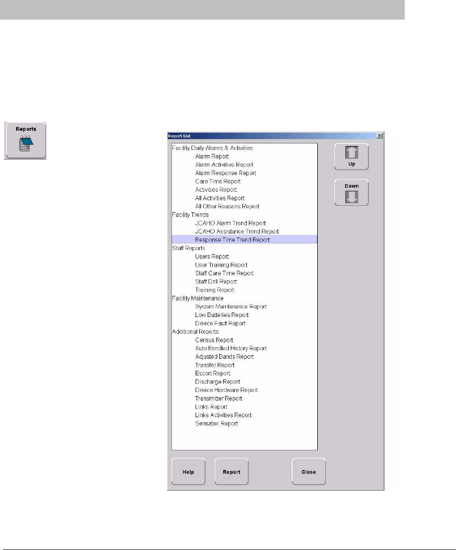
There are several Reports that enable you to
view information about the activities of the
system throughout the day, week, or
month. The Reports List is divided in
sections. The sections depend on how your
system is configured. The following section
provides detailed information about
viewing, printing, saving, using, and
filtering Reports.
To view a report
1. Click Reports on the toolbar.
The Report List window appears.
2. In the Report List window, use
the up and down arrows to select
the report you want to run.
3. Click Report or double click on
the selected report in the Report
List.
Chapter 5: Using System Reports
104 Series 6.0 Software (0510-1065-A) - User Guide
The Report window appears with the report you requested.
FIGURE 5.1: Report Window
Series 6.0 Software (0510-1065-A) - User Guide 105
Introduction
Report Buttons
The Report buttons allow you to save a report, print a report, page through a report, and adjust the view of the
report. You can also select to Filter the report and Close the report window.
Save
A report can be saved directly to the Client computer(s). To save a report, click on the save button
located in the upper left corner of the toolbar. Type in a File Name and select a File of Type from the
drop-down list. It is recommended that you do not select HTML or XLS as the file type due to
anomalies that may occur in the saved report.
Print
A report can be printed directly from the generated report’s window. To print a report, click on the
print icon located in the upper left corner of the toolbar. The printer must be connected and
configured to the Client computer.
Filter
By clicking the Filter button on the toolbar, you can select the criteria to run a specific report. Using
the Filter window, you can select which unit, which patient or asset, and what time frame you want
to view (24 hours, 7 days, or 30 days). Once you select your criteria, click OK.
FIGURE 5.2: Report Filter Window
Chapter 5: Using System Reports
106 Series 6.0 Software (0510-1065-A) - User Guide
Close
Use this button to close the reports window.
Arrow Buttons
Use this button to page up to the previous page.
Use this button to scroll up to the previous entry on the page.
Use this button to scroll down to the next entry on the page.
Use this button to page down to the next page.
Sort By Headings
Many of the reports allow you to sort information by column heading. Click on the column heading to sort by
that specific heading. Click on the column heading a second time to reverse the sort order. Reports can not be
saved or printed in the sorted format; they will default to their original format.
Series 6.0 Software (0510-1065-A) - User Guide 107
Introduction
Additional JCAHO Report Buttons
Additional Report Buttons are found on selective JCAHO Reports in the software. Following is an explanation of
these buttons.
First Page
Use this button to view the first page of a multiple page report.
Last Page
Use this button to view the last page of a multiple page report.
Next Page
Use this button to view the next page of the report.
Previous Page
Use this button to view the previous page of the report.
Actual Size
Use this button to adjust the view of the report to its actual size.
Fit Page
Use this button to fit the report to the size of the display screen.
Fit Width
Use this button to fit the report to the width of the display screen.
Zoom In
Use this button to maximize the view of the report by zooming in.
Zoom Out
Use this button to minimize the view of the report by zooming out.
Zoom Ratio
The zoom ratio corresponds to the size in which the report is currently being viewed. You can also
select to minimize or maximize a view by selecting the percent you which to adjust the view in the
Zoom Ratio drop-down list.

Chapter 5: Using System Reports
108 Series 6.0 Software (0510-1065-A) - User Guide
System Reports
The reports generated by the software have the same basic format. The header portion of the report identifies the
name of report. It also includes:.
Unit—the units included in the report.
TimeRange—the range selected for the report.
Patient —the patients or assets included in the report.
Facility Name—the name of the facility.
Facility Address—the address of the facility.
The bottom portion of the report varies depending on the report. Following are details on each individual report
listed in the Report List.
Daily Alarms and Activities (Tracer Level 2)
Alarm Report
The Alarm Report lists all of the Red (high priority) alarms that occurred in the system within a specified period of
time. The Alarm Report includes:
Name—the name of the patient or asset to whom the transmitter is assigned.
Activity—the description of the alarm’s activity.
Time—the time of the alarm.
Tx ID—the identification number of the transmitter.
Tx Type—the type of transmitter
Location—the device that received the event.
Risk—the risk level assigned to the patient or asset.
By clicking the Filter button on the bottom of the Alarm report you can also select the criteria to run a specific
Alarm Report.

Series 6.0 Software (0510-1065-A) - User Guide 109
System Reports
Alarm Activities Report
The Alarm Activities Report lists all of the alarms that occurred in the system within a specified period of time.
The Alarm Activities Report includes:
Time—the time the alarm occurred.
Name—the name of the patient or asset to whom the transmitter is assigned.
Type—the type of event recorded.
Activity—the description of the alarm’s activity.
Tx ID—the identification number of the transmitter.
Tx Type—the type of transmitter that sent the signal.
Location—the device that received the event.
User—the staff member who cleared the event (when applicable).
Clear—the event reason used to clear the alarm (when applicable).
By clicking the Filter button on the bottom of the report, you can also select the criteria to run a specific Alarm
Activities Report.
Alarm Response Report
The Alarm Response Report enables you to gauge how your staff responds to system events. The Alarm Response
Report includes:
Name—the name of the patient or asset to whom the transmitter is assigned.
Tx ID—the identification number of the transmitter.
Location—the device, unit, and/or room that received the alarm.
Activity—the description of the event’s activity.
Event Time—when the event occurred.
Clear Time—when the event was cleared.
Response Time—the amount of time it took for the staff to respond to and clear the alarm at the
device.
Clear Reason—the event reason used to clear the alarm (when applicable).
By clicking the Filter button on the bottom of the report, you can also select the criteria to run a specific Alarm
Response Report.

Chapter 5: Using System Reports
110 Series 6.0 Software (0510-1065-A) - User Guide
Care Time Report (ICM only)
The Care Time Report enables you to gauge how your staff responds to system events. The Care Time Report
includes:
Name—the name of the patient or asset to whom the transmitter is assigned.
Care Time—the difference between the time the device was reset and the alarm was actually cleared at
the computer.
Reset Time—when the device was reset.
Clear Time—when the event was cleared at the computer.
Location—the device, unit, and/or room that received the alarm.
Activity—the description of the event’s activity.
Clear Reason—the event reason used to clear the alarm (when applicable).
User—the staff member who responded to the event.
By clicking the Filter button on the bottom of the report, you can also select the criteria to run a specific Alarm
Response Report.
Activities Report
The Activities Report lists all of the activities or events that have occurred in the system with respect to each
patient or asset.
The Activities Report includes:
Name—the name of the patient or asset to whom the transmitter is assigned.
Activity—the description of the event’s activity.
Type—the type of event recorded.
Time—the time of the event.
Tx ID—the identification number of the transmitter.
Tx Type—the type of transmitter.
Location—the device, unit and/or room that received the event.
User—the staff member who authorized or cleared the event (when applicable).
Risk—the risk level assigned to the patient or asset.
By clicking the Filter button on the bottom of the report, you can also select the criteria to run a specific Activities
Report.
NOTE: This report is sorted alphabetically by patient or asset and then by event time.

Series 6.0 Software (0510-1065-A) - User Guide 111
System Reports
All Activities Report
The All Activities Report lists all of the activities or events that have occurred in the system. The All Activities
Report includes:
Time—the time of the event or activity.
Name—the device, or the name of the patient or asset to whom the transmitter is assigned.
Type—the type of event recorded.
Activity—the description of the event’s activity.
Tx ID—the identification number of the transmitter.
Tx Type—the type of transmitter that sent the signal.
Location—the device that received the event.
User—the staff member who authorized the activity (when applicable).
Clear—the event reason used to clear the alarm (when applicable).
By clicking the Filter button on the bottom of the report you can select the criteria to run a specific All Activities
Report.
All Other Reasons Report
The All Other Reasons Report provides a summary of all the “other” reasons used when clearing an alarm.
“Other” are the reasons for alarm events that are manually entered by staff members when they clear alarms.
These reasons are reflected on the JCAHO report as well. The All Other Reasons Report includes:
Time—the time of the event.
Name—the name of the patient or asset to whom the transmitter is assigned or the auto-enrolled
transmitter.
Type—the type of event recorded.
Activity—the description of the event.
Tx ID—the identification number of the transmitter involved.
Tx Type—the type of transmitter that sent the signal.
Location—the device that received the event.
User—the staff member who cleared the event (when applicable).
Clear Reason—the manually entered reason (“other” reasons) for the event.
By clicking the Filter button on the bottom of the All Other Reasons Report, you can select the criteria to run a
specific report.
Chapter 5: Using System Reports
112 Series 6.0 Software (0510-1065-A) - User Guide
Facility Trends (Tracer Level 3)
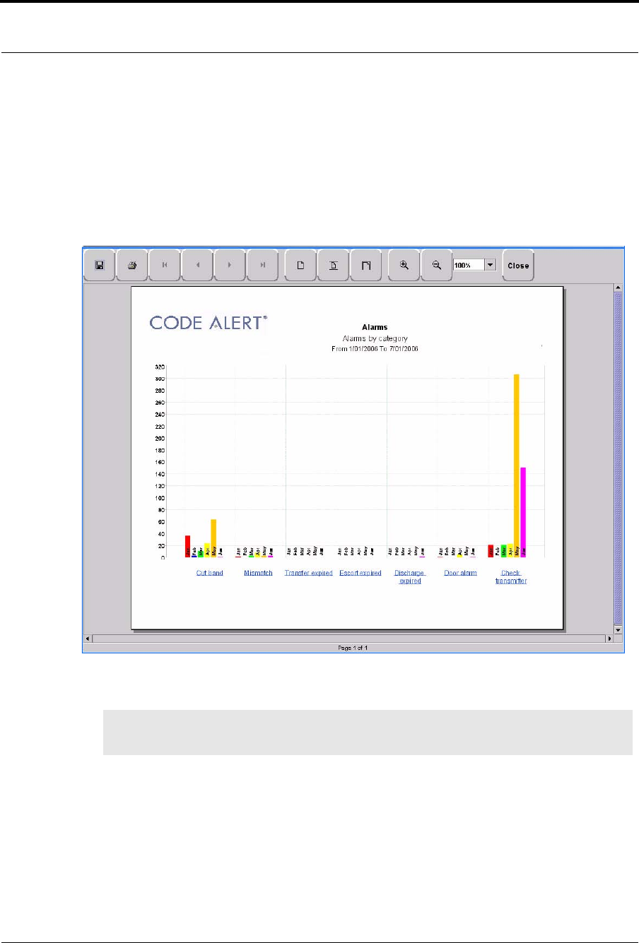
JCAHO Alarm Trend Report
The JCAHO Alarm Trend Report lists the different events that have occurred in the system in six-month
segments and then provides a bar graph to track the events. By clicking the Print icon, you can print this report.
FIGURE 5.3: JCAHO Alarm Trend Report
NOTE: If the Event cause is “Other,” go to the All Other Reasons Report and review the memo field
for more information. You can also select the “Other” hyper-link from any JCAHO Details Report.
Series 6.0 Software (0510-1065-A) - User Guide 113
System Reports
JCAHO Alarm Trend Reason Report
Click on the links at the bottom of the JCAHO Alarm Trend Report to access the JCAHO Alarm Trend Reason
Report. This report provides detailed information about the Event Causes that were selected each time an Event
was cleared.
FIGURE 5.4: JCAHO Alarm Trend Reason Report
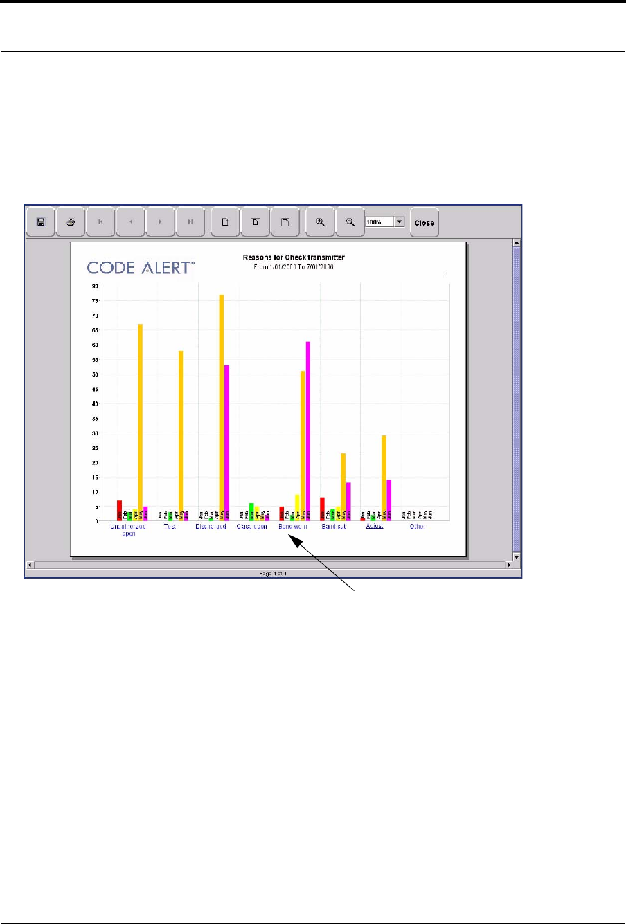
JCAHO Alarm Trend Reasons Detail Report
Clicking on the Event Cause link at the bottom of the JCAHO Alarm Trend Reason Report opens the Reasons
Detail Report that lists all events that went into the calculation of the JCAHO Alarm Trend Report. The Reasons
Detail Report includes:
Date—the date and time the event occurred.
Response Time—the amount of time it took for the staff to respond and clear the event.
User—the staff member who responded to the event.
Location—the unit or room to which the device is assigned.
Tx—the identification number of the transmitter.
Name—the name of the device or the patient or asset to whom the device is assigned.
Event Cause
Chapter 5: Using System Reports
114 Series 6.0 Software (0510-1065-A) - User Guide
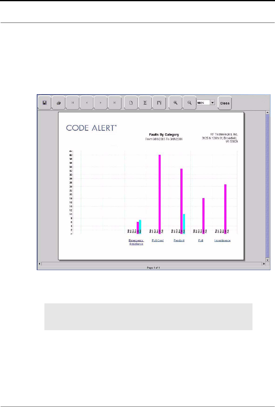
JCAHO Assistance Trend Report
The JCAHO Assistance Trend Report supports events generated by Emergency Assistance, Pull Cord, Pendant,
Fall Monitoring, and Incontinence devices. This report lists the different events for these devices that have
occurred in the system in six-month segments and then provides a bar graph to track the events. By clicking the
Print icon, you can print this report.
FIGURE 5.5: JCAHO Assistance Trend Report
NOTE: If the Event cause is “Other,” go to the All Other Reasons Report and review the
memo field for more information. You can also select the “Other” hyper-link from any
JCAHO Details Report.
Series 6.0 Software (0510-1065-A) - User Guide 115
System Reports
JCAHO Assistance Trend Reason Report
Click on the links at the bottom of the JCAHO Assistance Trend Report to access the JCAHO Assistance Trends
Reason Report. This report provides detailed information about the Event Causes that were selected each time an
Event was cleared.
FIGURE 5.6: JCAHO Assistance Trend Reason Report
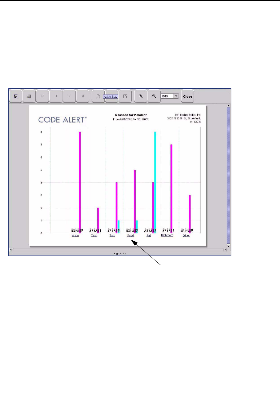
JCAHO Assistance Trend Detail Report
Clicking on the Event Cause link at the bottom of the Reason Report opens a Reason Detail Report that lists all
events that went into the calculation of the JCAHO Assistance Trend Report. The Reasons Detail Report
includes:
Date—the date and time the event occurred.
Response Time—the amount of time it took for the staff to respond and clear the event.
User—the staff member who responded to the event.
Location—the unit or room to which the device is assigned.
Tx ID—the identification number of the transmitter.
Name—the name of the device or the patient or asset to whom the device is assigned.
Event Cause
Chapter 5: Using System Reports
116 Series 6.0 Software (0510-1065-A) - User Guide
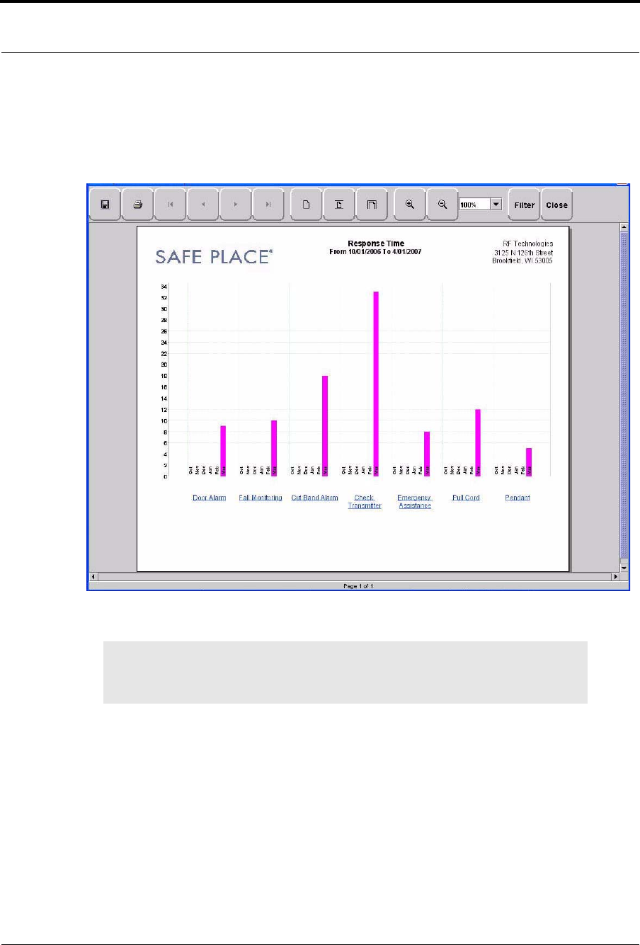
Response Time Trend Report
The Response Time Trend Report lists the response time for specific events that have occurred in the system in
six-month segments and then provides a bar graph to track the response time (in seconds) for those events.
FIGURE 5.7: Response Time Trend Report
NOTE: If the Event cause is “Other,” go to the All Other Reasons Report and review the
memo field for more information. You can also select the “Other” hyper-link from any
JCAHO Details Report.
Series 6.0 Software (0510-1065-A) - User Guide 117
System Reports
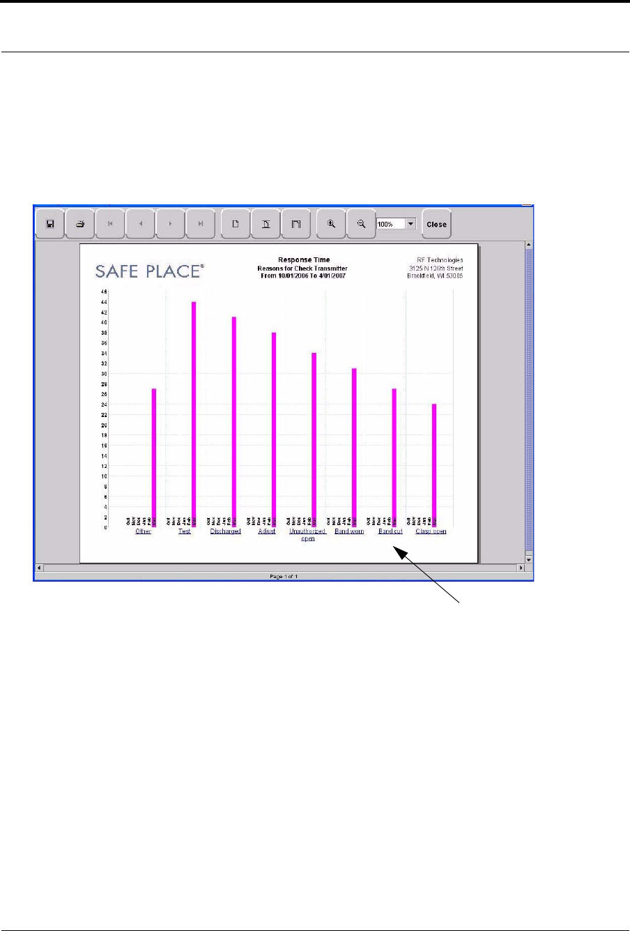
Response Time Trend Reason Report
Click on the links at the bottom of the Response Time Trend Report to access the Response Time Trend Reason
Report. This report provides detailed information about the Event Cause that was selected each time an Event
was cleared.
FIGURE 5.8: Response Time Trend Reason Report
Response Time Trend Reasons Detail Report
Clicking on the Event Cause link at the bottom of the Reasons Report opens the Reasons Detail Report that lists
all events that went into the calculation of the Response Time Report. The Reasons Detail Report includes:
Date—the date and time the event occurred.
Response Time—the amount of time it took for the staff to respond and clear the event.
User—the staff member who responded to the event.
Location—the unit or room to which the device is assigned.
Tx ID—the identification number of the transmitter.
Name—the name of the device or the patient or asset to whom the device is assigned.
Event Cause
Chapter 5: Using System Reports
118 Series 6.0 Software (0510-1065-A) - User Guide
Staff Reports (Tracer Level 4)
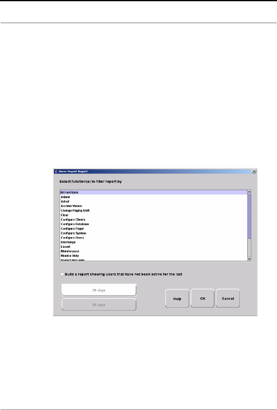
Users Report
The User Report lists all of the staff members who are current users of the system. The User Report includes:
User—the name of the staff member.
Login—the login name of the staff member.
Assigned Function— all functions assigned to the user.
Door Card Access— if the user has door card access.
By clicking the Filter button on the bottom of the Users Report, you can filter the report by assigned function as
well as build a report showing users that have not been active in the system for the last 30 days or maximum of 60
days (the previous month plus the preceding number of days in the current month.
FIGURE 5.9: User Report Filter window

Series 6.0 Software (0510-1065-A) - User Guide 119
System Reports
User Training Report
The User Training Report tracks the use of the on-line user help feature by staff members with login. The User
Training Report includes:
Event Time—the time the user help file was opened.
User—the staff member who opened the user help file.
To p i c —the topic or subject matter of the user help file.
Staff Care Time Report
The Staff Care Time Report enables you to gauge how your staff responds to system events. The Staff Care Time
Report includes:
Responder—the staff member who responded to the event.
Care Time—the difference between the time the event occurred and the time it was cleared at the
computer.
Care Started—the time the event occurred.
Care Completed—when the event was cleared at the computer.
Location—the device, unit, and/or room that received the alarm.
Activity—the description of the event’s activity.
Clear Reason—the event reason used to clear the alarm (when applicable).
Name—the name of the patient or asset to whom the transmitter is assigned.
By clicking the Filter button on the bottom of the report, you can also select the criteria to run a specific Alarm
Response Report.

Chapter 5: Using System Reports
120 Series 6.0 Software (0510-1065-A) - User Guide
Staff Drill Report
The Staff Drill Report lists the drills performed by the staff members. The Staff Drill Report includes:
Time—the time of the staff drill.
Comments—the comments about the drill function performed.
User—the staff member who authorized and performed the drill.
Training Report
The Training Report identifies the training delivered to the patient upon admission. The Training Report
includes:
Name—the name of the patient.
Time—the date the delivery of training was entered into the system.
Handout Training—the date any handout was delivered to the patient.
Video Training—the date any video was shown to the patient.
Verb al—the time any verbal training was delivered to the patient.
User—the staff member who entered dates into the system.
Location—the unit to which the patient is assigned.

Series 6.0 Software (0510-1065-A) - User Guide 121
System Reports
Facility Maintenance (Tracer level 5)
System Maintenance Report
The System Maintenance Report lists the maintenance functions performed on the system. The System
Maintenance Report includes:
Time—the time the maintenance was performed.
Comments—the comments about the maintenance function performed.
User—the service personnel who authorized and performed the maintenance.
Low Batteries Report
The Low Batteries Report provides a list of the transmitters and devices that currently have transmitted low
battery signals. The Low Batteries Report includes:
Name—the name of the device or the patient or asset to whom the transmitter is assigned.
Time—the time the low battery was recognized by the system.
Tx ID—the identification number of the transmitter.
Unit—the unit of the device or the patient or asset to whom the transmitter is assigned.
Device—the type of device reading the transmitter signal.
Room—the room of the device or the patient or asset to whom the transmitter is assigned.
Device Fault Report
The Device Fault Report provides detailed information about issues that occurred with system devices. This
Device Fault Report includes:
Time—the time the activity was reported.
Type—the type of event recorded.
Comport—the comport to which the device is assigned.
Physical Address—the network address of the device within the comport.
Location—the unit and room to which the device is assigned.
Last CheckIn—the last time the device checked into the system.
Activity—the description of the event’s activity,.
By clicking the Filter button on the bottom of the Device Fault Report, you can select the criteria to run a specific
report.

Chapter 5: Using System Reports
122 Series 6.0 Software (0510-1065-A) - User Guide
Additional Reports
Census Report
The Census Report lists all of the patients, in the unit you are monitoring, that are currently admitted in the
system. This report is sorted alphabetically by unit and then by patient. The Census Report includes:
Name—the name of the patient.
Gender—the sex of the patient.
Unit—the unit to which the patient is assigned.
Room—the patient’s room number.
Tx ID—the identification number of the alarming band or Wander Management transmitter assigned
to the patient.
Admit Time— the time at which the patient was admitted.
Admitted By—the staff member who performed the admission.
Risk—the risk level assigned to the patient.
Auto Enrolled History Report
The Auto Enrolled History Report lists the alarming band transmitters that were auto-enrolled. This report is a
history report; therefore, not all transmitters listed may be actively monitored by the system at the time of the
report. The report includes:
Enroll Time—the time when the transmitter was auto enrolled.
Location—the alarming band receiver (ABR) that picked up the auto-enroll and the unit the device is
assigned to.
Type—the type of event recorded.
Tx ID—the identification number of the transmitter.
By clicking the Filter button on the bottom of the Auto-Enrolled History Report, you can also select the criteria
to run a specific report.

Series 6.0 Software (0510-1065-A) - User Guide 123
System Reports
Adjusted Bands Report
The Adjusted Bands Report enables you to see which alarming band transmitter bands were adjusted. The Adjust
Bands Report includes:
Name—the name of the patient or asset to whom the transmitter is assigned.
Activity—the description of the band adjustment’s activity.
Type—the type of event recorded.
Time—the time of the event.
Tx ID—the identification number of the transmitter.
Location—the device that received the event.
User—the staff member who authorized the adjustment (when applicable).
Risk—the risk level assigned to the patient or asset.
By clicking the Filter button on the bottom of the Adjusted Bands Report, you can also select the criteria to run a
specific report.
Transfer Report
The Transfer Report lists all of the patients or assets who were transferred from one protected area to another
protected area. The Transfers Report includes:
Name—the name of the patient or asset.
Activity—the description of the transfer’s activity.
Type—the type of event recorded.
Time—the time of the event
Tx ID—the identification number of the transmitter (when applicable).
Location—the device that received the event.
User—the staff member who authorized the transfer (when applicable).
Risk—the risk level assigned to the patient or asset.
By clicking the Filter button on the bottom of the Transfer Report, you can select the criteria to run a specific
report.

Chapter 5: Using System Reports
124 Series 6.0 Software (0510-1065-A) - User Guide
Escort Report
The Escort Report lists all of the patients or assets who were escorted from a protected area and back to the same
protected area. The Escort Report includes:
Name—the name of the patient or asset to whom the transmitter is assigned.
Activity—the description of the escort’s activity.
Type—the type of event recorded.
Time—the time of the event.
Tx ID—the identification number of the transmitter.
Location—the device that received the event.
User—the staff member who authorized the escort (when applicable).
Risk—the risk level assigned to the patient or asset.
By clicking the Filter button on the bottom of the Escort Report, you can select the criteria to run a specific
report.
Discharge Report
The Discharge Report lists all of the patients or assets that were discharged from the system within a specified
period of time. The Discharge Report includes:
Name—the name of the patient or asset.
Activity—the description of the discharge’s activity.
Type—the type of event recorded.
Time—the time of the event.
Tx ID—the identification number of the transmitter (when applicable).
Location—the device that received the event.
User—the staff member who authorized the discharge (when applicable.)
Risk—the risk level assigned to the patient or asset.
By clicking the Filter button on the bottom of the Discharge Report, you can select the criteria to run a specific
report.

Series 6.0 Software (0510-1065-A) - User Guide 125
System Reports
Device Hardware Report
The Device Hardware Report lists all of the devices in the system. The report includes:
Description—the name of the device.
Type—the type of device.
Comport—the comport to which the device is assigned.
Physical Address—the network address of the device within the comport.
Location—the unit to which the device belongs
H/w Version—the device hardware version.
S/w Version—the device software version.
Linger—the linger time assigned to the EAC.
Transmitter Report
The Transmitter Report provides general details about transmitters admitted to the system. The Transmitter
Report includes:
Tx —the identification number of the transmitter.
Tx Type—the type of transmitter.
Name—the name of the patient or asset.
Location—the unit to which the device belongs.
Links Report
The Links Report provides general details about mothers and infants admitted to the system. The Link Report
includes:
Link Tx ID—the ID number of the mother transmitter.
Tx ID—the identification number of the infant transmitter linked to the mother transmitter.
Name—the name of the infant.
Unit Name—the unit to which the infant transmitter is associated.
Link Time—the time at which the infant was linked.
NOTE: If the device belongs to more than one unit, only the first unit (alphabetically) is
displayed.

Chapter 5: Using System Reports
126 Series 6.0 Software (0510-1065-A) - User Guide
Links Activities Report
The Links Activities Report is a history report of all activities related to mother and infant transmitters that were
linked in the system. This report includes any activity that triggered an event for the linked transmitters. The
Links Activities Report includes:
Name—the name of the infant or mother.
Tx—the identification number of the infant transmitter involved.
Activity—the description of the event.
Time—the time of the event.
MTx—the identification number of the mother transmitter involved.
Location—the device that received the event.
User—the staff member who cleared the event (when applicable).
By clicking the Filter button on the bottom of the Link Activities Report, you can select the criteria to run a
specific report.
Sensatec Report
The Sensatec Report enables you to gauge how your staff responds to Sensatec events. The Sensatec Report
includes:
Name—the name of the patient to whom the control unit is assigned.
Tx ID—the identification number of the control unit.
Location—the device, unit, and/or room that received the alarm.
Activity—the description of the event’s activity.
Event Time—when the event occurred.
Clear Time—when the event was cleared.
Care Time—the amount of time it took for the staff to respond and clear the white alarm.
Clear Reason—the event reason used to clear the alarm (when applicable).
By clicking the Filter button on the bottom of the report, you can also select the criteria to run a specific Sensatec
Report.

Series 6.0 Software (0510-1065-A) - User Guide 127
Patient Reports
Patient Reports
Patient reports are specific to the individual patient. They are accessed from the Main tab of the patient’s Admit
Information window. The patient reports are as follows:
Review Info Report
The Review Info Report identifies admit information that was entered for the patient. The Review Info Report
includes the patient’s picture, if entered, and demographic information for the patient and the patient’s contacts.
It also includes the patient’s allergies, medication information, medical history information and any special
instructions that were entered.
Review Activity Report
The patient’s Review Activity Report lists all of the activities or events that have occurred in the system with
respect to the patient. The Review Activities Report includes:
Time—the time of the event.
Activity—the description of the event’s activity.
Type—the type of event recorded.
Reason—the event reason used to clear the alarm (when applicable).
User—the name of the patient to whom the transmitter is assigned.
Location—the device, unit and/or room that received the event.
User—the staff member who authorized or cleared the event (when applicable).
Tx Type—the type of transmitter.
Tx ID—the identification number of the transmitter.
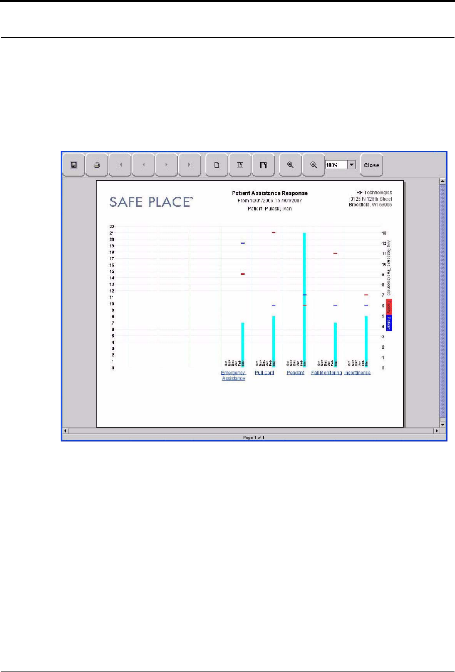
Chapter 5: Using System Reports
128 Series 6.0 Software (0510-1065-A) - User Guide
Review Response Report
The Review Response Report lists the response time for specific events that have occurred for the patient in six-
month segments and then provides a bar graph to track the number of events. The blue mark indicates the events
for the patient, the red mark indicate the average events for the facility.
FIGURE 5.10: Review Response Report
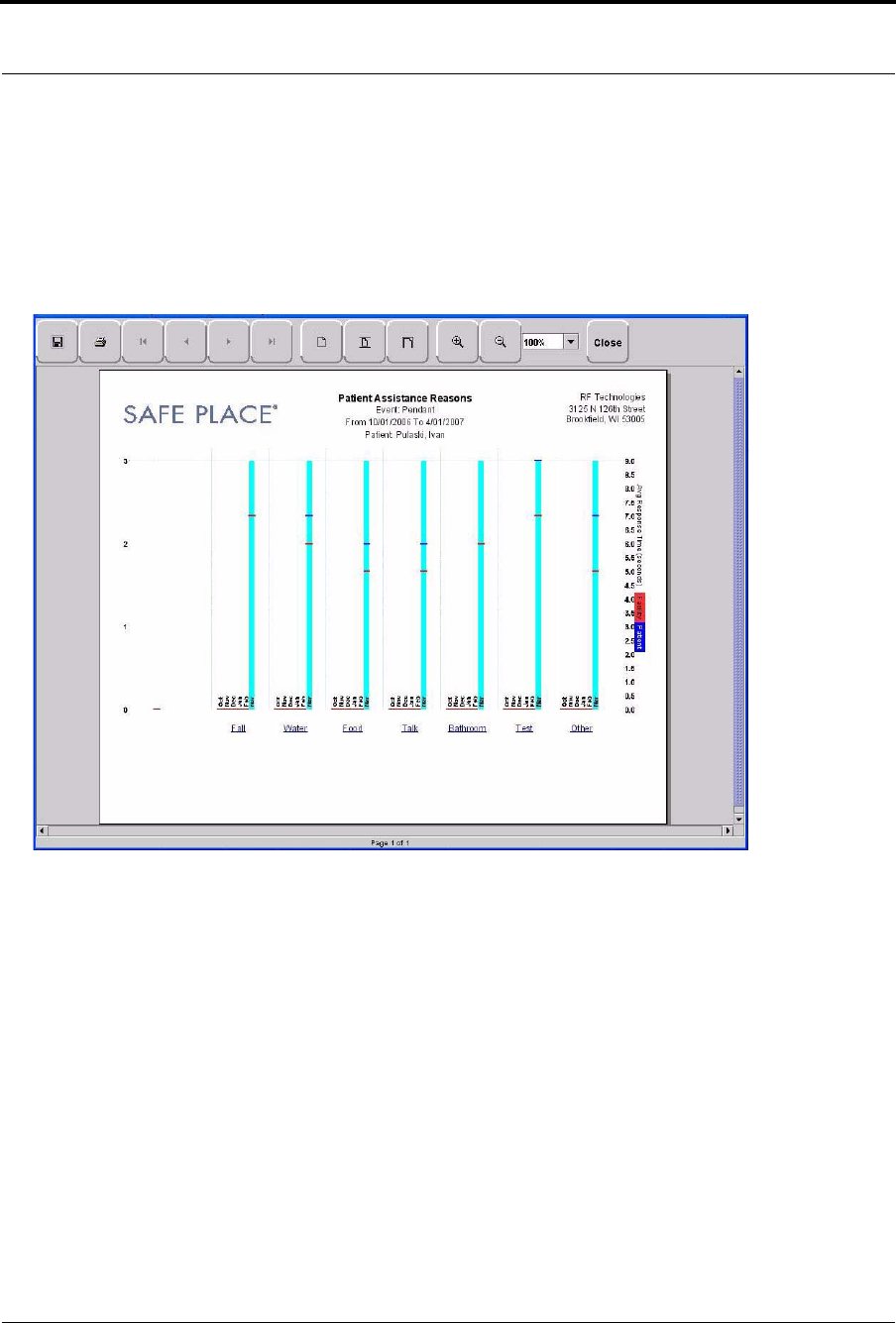
Series 6.0 Software (0510-1065-A) - User Guide 129
Patient Reports
Review Response Reason
By clicking on an event link at the bottom of the report, you can access the Response Reason Report. This report
provides detailed information about the Event Cause that was selected each time an Event was cleared for the
patient and then provides a bar graph to track the response time (in seconds) for those events. The blue mark
indicates the response time for the patient, the red mark indicate the average response time for the facility.
FIGURE 5.11: Review Response Reason Reports
Review Response Reason Detail Report
Clicking on the Event Cause link at the bottom of the Reasons Report opens a Reason Detail Report that lists all
events that went into the calculation of the Review Response Report.
The Detail Report includes:
Date—the date and time the event occurred.
Response Time—the amount of time it took for the staff to respond and clear the event.
Responder—the staff member who responded to the event.
Tx ID—the identification number of the transmitter.
Name—the name of the device or the patient to whom the device is assigned.

Chapter 5: Using System Reports
130 Series 6.0 Software (0510-1065-A) - User Guide
Asset Reports
Asset reports are specific to the individual asset. The Asset Transmitter Report is accessed from the Assets selection
on the Menu bar of the Main window. The Asset Activities Report is accessed from the Main tab of the Asset
Admit Information window.
Asset Transmitter Report
The Asset Transmitter Report lists all the assets that are currently admitted in the system. The Asset Transmitter
Report includes:
Make—the assets manufacturer’s information.
Model—the model/description of the asset.
SN—the serial number of the asset.
Tx ID—the identification number of the transmitter assigned to the asset.
Location—the unit or room to which the asset is assigned.
Asset Activities Report
The Asset Activity Report lists all of the activities or events that have occurred in the system with respect to the
asset. The Asset Activities Report includes:
Time—the time of each event.
Activity—the description of the event’s activity.
Type—the type of event recorded.
Tx ID—the identification number of the transmitter.
Location—the device, unit and/or room that received the event.
User—the staff member who authorized or cleared the event (when applicable).
Reason—the event reason used to clear the alarm (when applicable).

Series 6.0 Software (0510-1065-A) - User Guide 131
Asset Reports
This page intentionally left blank.

Chapter 5: Using System Reports
132 Series 6.0 Software (0510-1065-A) - User Guide