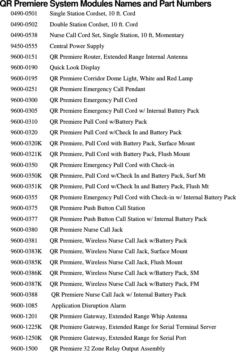
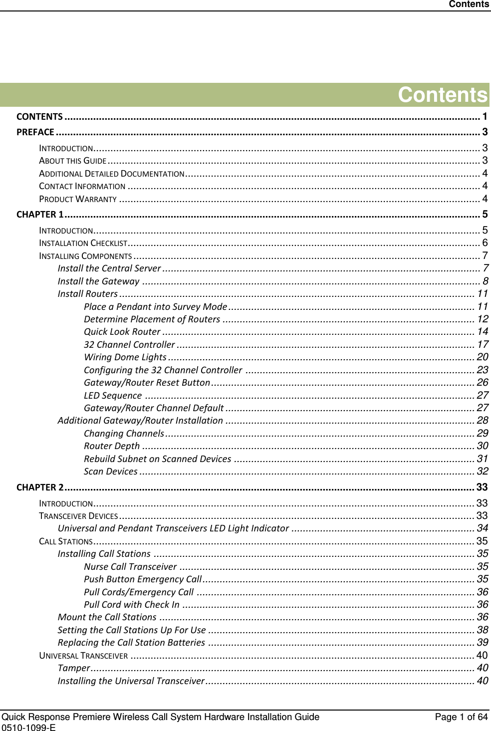
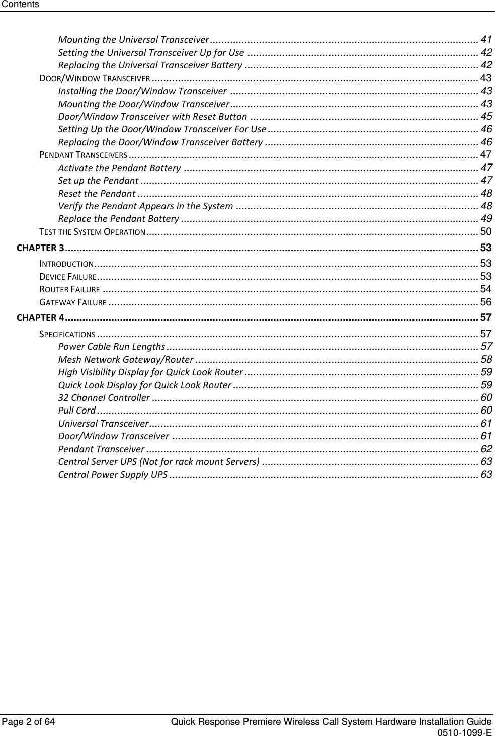
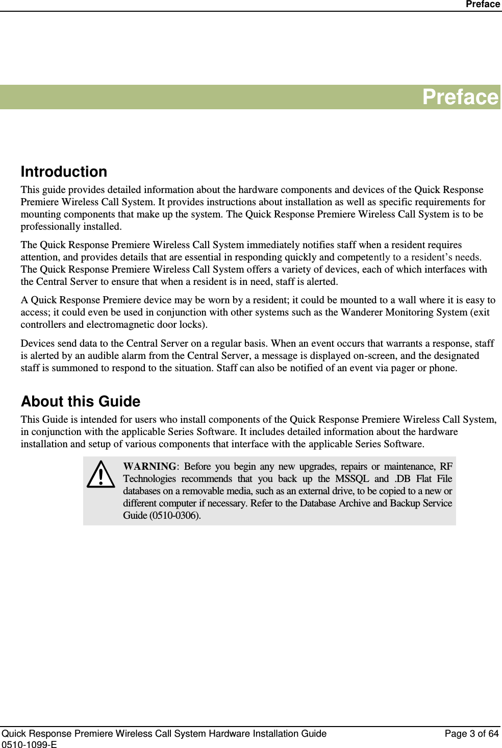
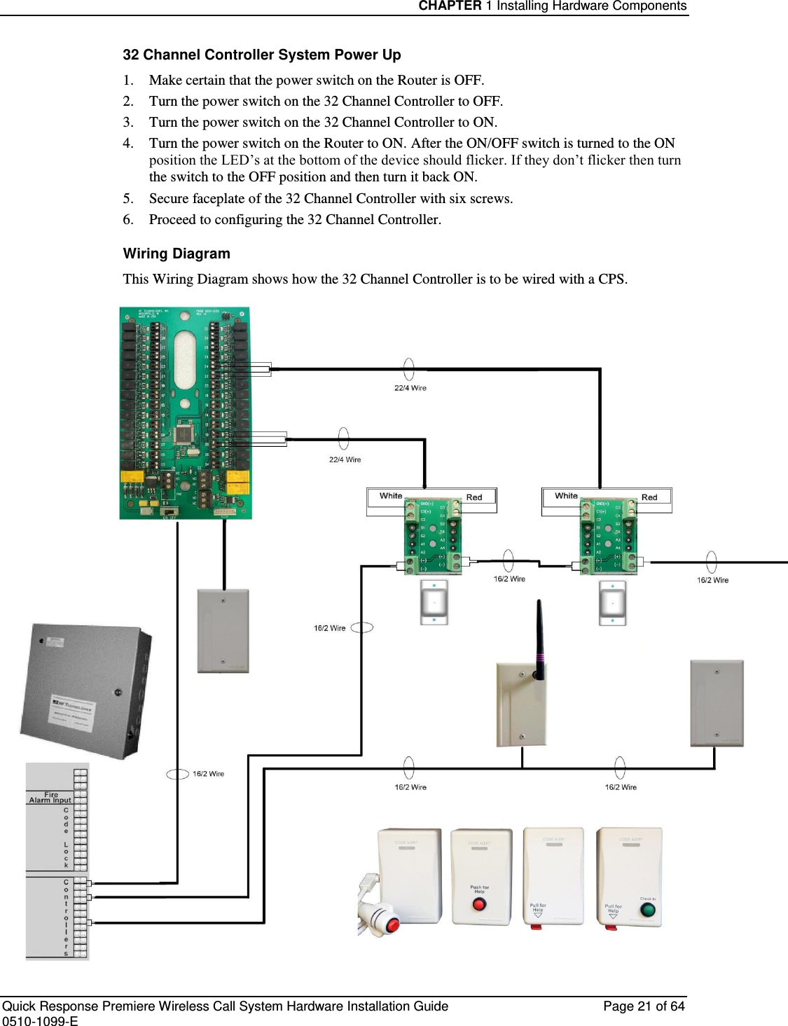
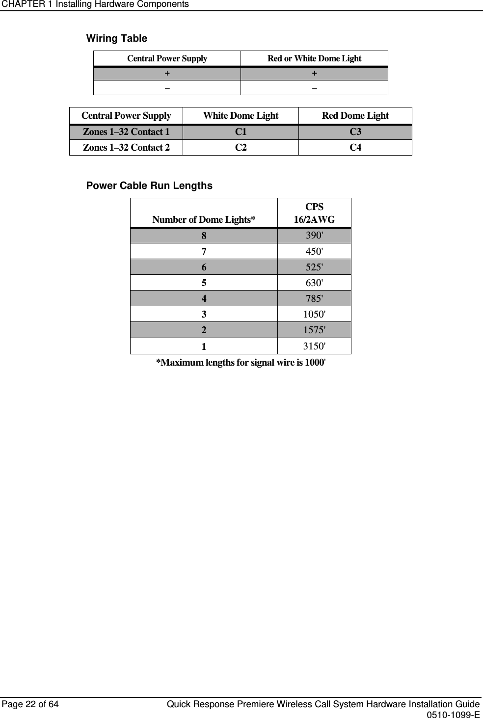
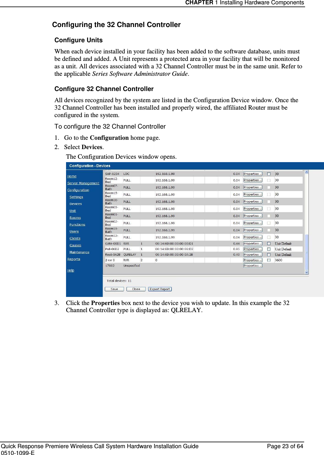
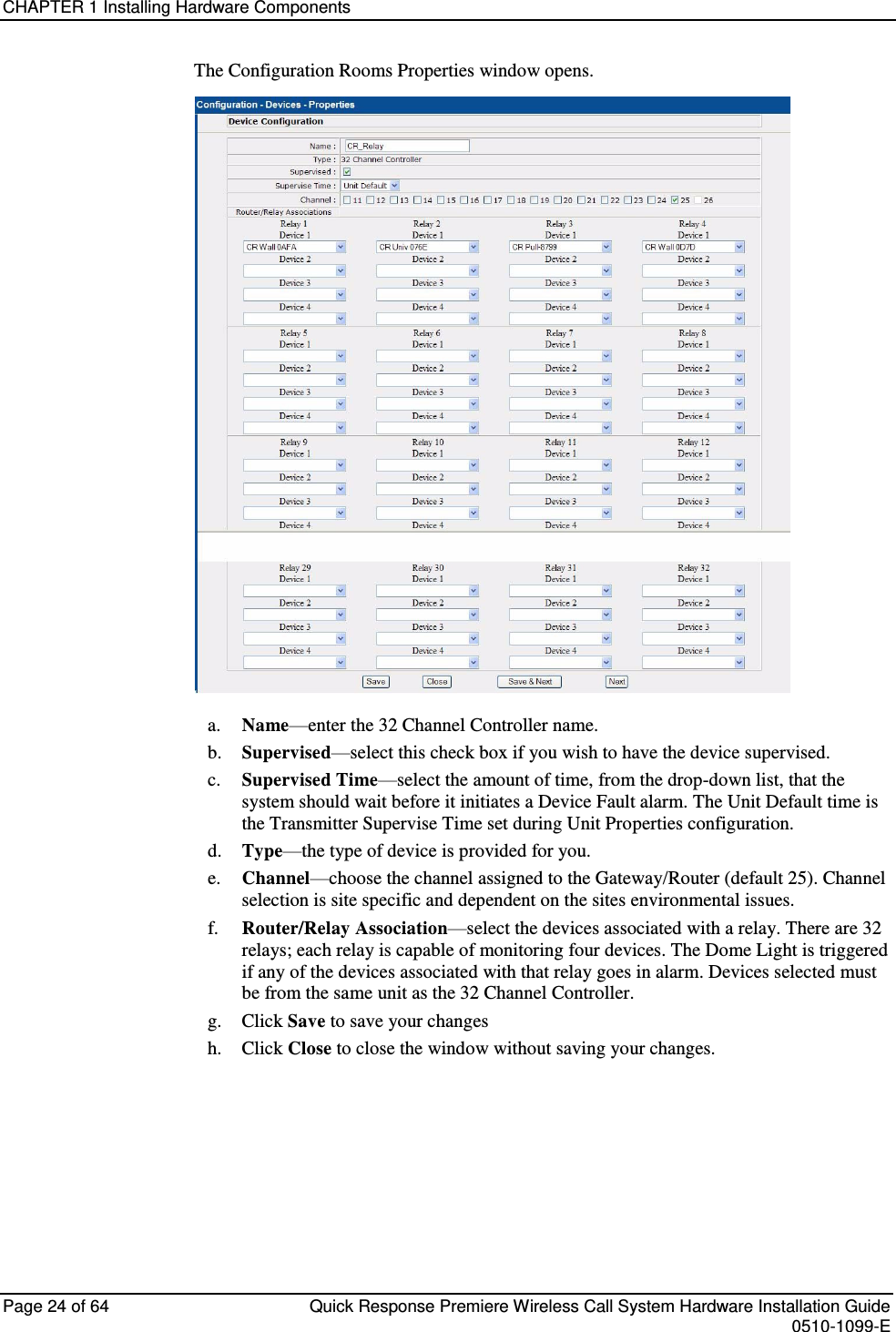
R F Technologies SRTCCZ24V3 Quick Response Premiere Router/Gateway User Manual
R F Technologies Inc Quick Response Premiere Router/Gateway
UserManual.wiki
>
R F Technologies
>
SRTCCZ24V3 User Manual
User Manual
Navigation menu
Upload a User Manual
Namespaces
Wiki Guide
HTML
PDF
Info
Views
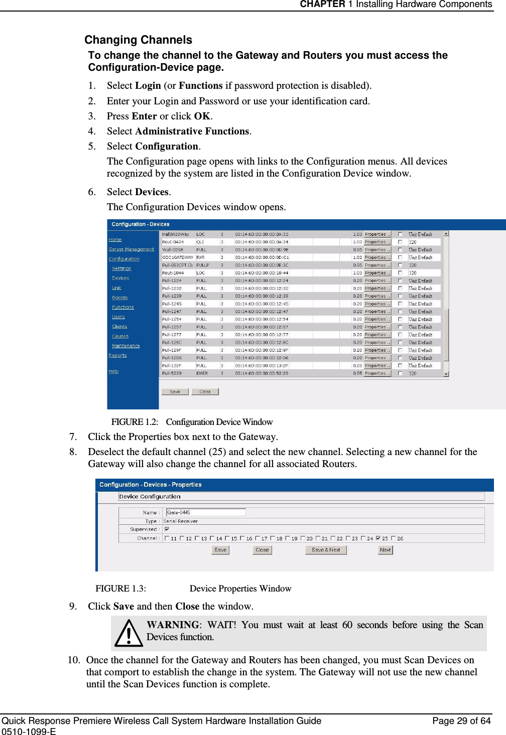
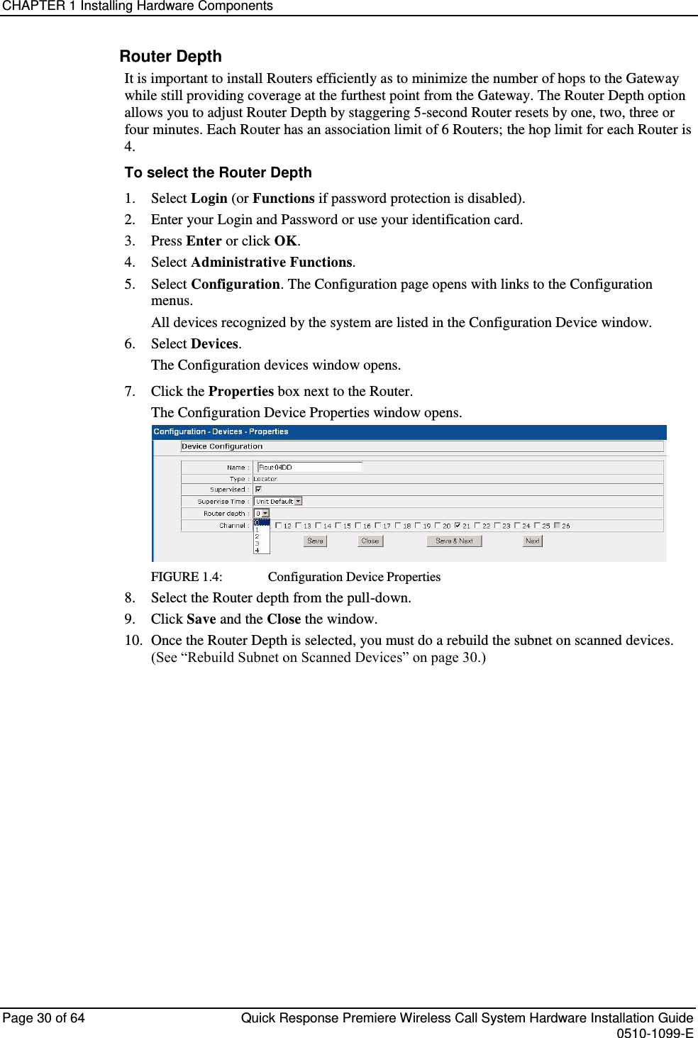
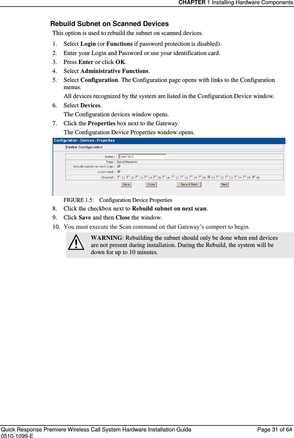
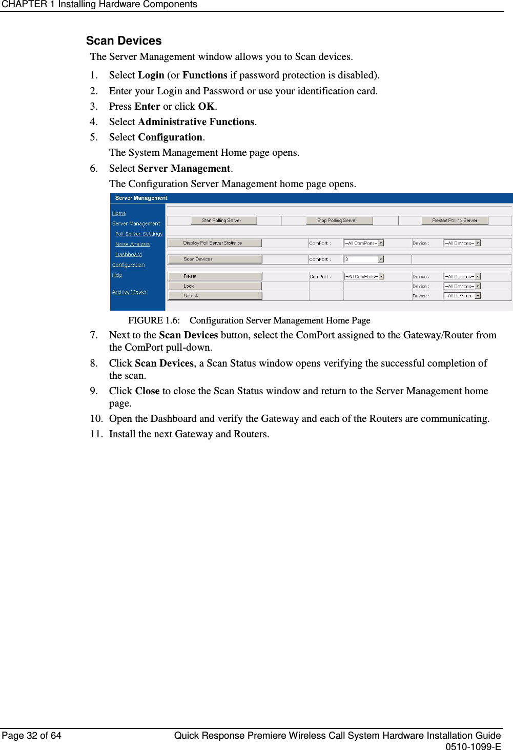
User Manual
Discussion / Help
Navigation