Manual
Notchcell 20W
Operating Manual
Programmable Type
Version 1.0

NOTCHCELL 20W OPERATING MANUAL
R-tron America, Inc. Page: 2 / 57
CONTENT
1. OVERVIEW 3
2. SPECIFICATIONS 4
2.1 NOTCHCELL 20W 4
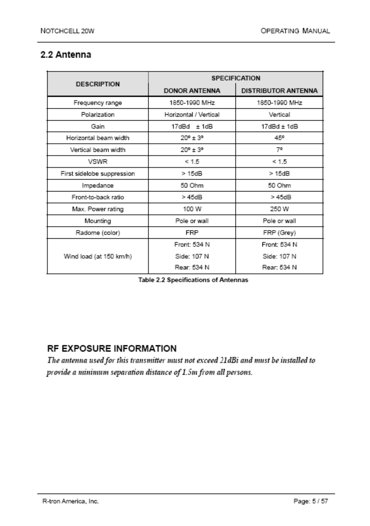
2.2 ANTENNA 5
3. INSTALLATION 6
3.1 GENERAL 6
3.2 TECHNICAL SPECIFICATION 7
3.3 INSTALLING INFORMATION 11
4. OPERATION 29
4.1 ISOLATION TEST POCEDURE OF ANTENNA 29
5. GRAPHIC USER INTERFACE 31
5.1 INTRODUCTION 31
5.2 GETTING STARTED 32
5.3 CONNECTING TO THE NOTCHCELL 33
5.4 SETUP & STATUS MODE SYSTEM DISPLAY 35
5.5 REPEATER SET USING GUI 37
APPENDIX A. SYSTEM PARAMETERS 49
A.1 SYSTEM STATE WINDOW 49
A.2 MENU SELECTION WINDOW 52
APPENDIX B. MODEM 55
B.1 SYSTEM WINDOW 55
B.2 MODEM WINDOW 57
NOTCHCELL 20W OPERATING MANUAL
R-tron America, Inc. Page: 3 / 57
1. Overview
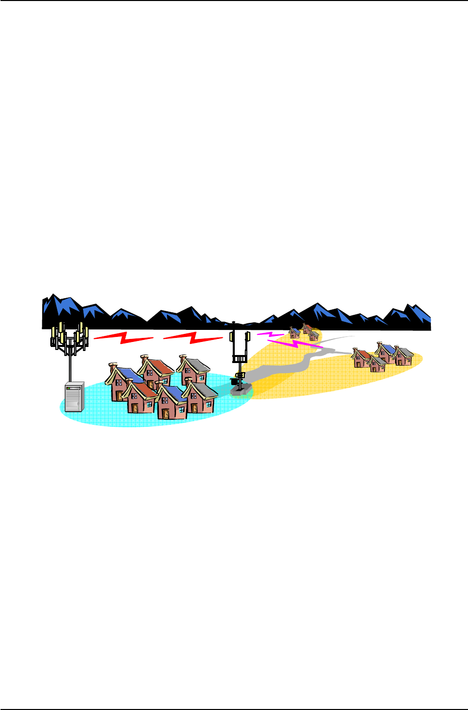
NOTCHCELL repeater can be used in CDMA service hole spots like in-buildings,
underground and tunnels to cover its service area. This repeater system designed for
dual and simultaneous service, namely, it receives signals from the base station
through donor antenna, amplifies the signals and re-transmits it to one or other
mobile terminals. Also, it amplifies the signals which comes from mobile terminals
through distributor antenna and re-amplifies it to base station.
Using local OMT(Operation and Maintenance Terminal) which is connected between
repeater control board and personal or laptop computer, it is possible to check or to
control repeater status. With wireless modem which is in the repeater, it also enables
to monitor Sprint WNMC(Wireless Network Management Center) in a remote place.
Figure 1.1 NOTCHCELL repeater
NOTCHCELL 20W OPERATING MANUAL
R-tron America, Inc. Page: 4 / 57
2. Specifications
2.1 Notchcell 20W Repeater
SPECIFICATION
ITEM
DOWN-LINK UP-LINK
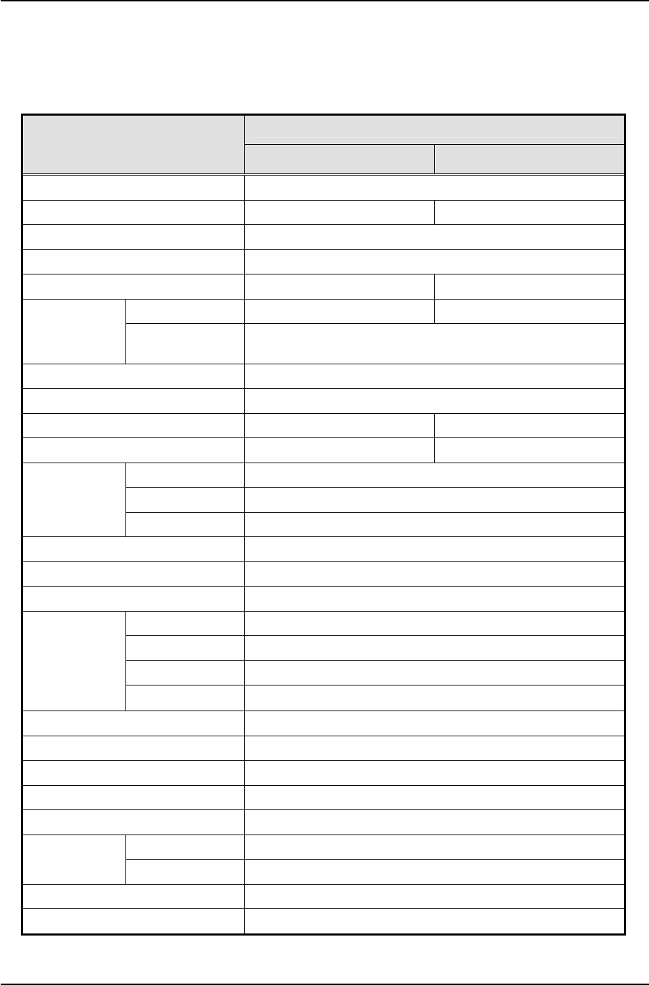
Repeater Type Band Selective (5,10,15,20,5+5,10+5,15+5MHz)
Frequency Range 1930 ~ 1990MHz 1850 ~ 1910MHz
CDMA Frequency Error < ± 0.05ppm
Rho (Pilot Only) > 0.912
RF Output Power 43dBm / Total 28dBm / Total
Operating ~ -30dBm ~ -30dBm
RF Input
Level Maximum
(abnormal) +10dBm
System Gain 65~95dB
Gain Control 0 ~ 30dB/1dB step
ALC(Automatic Level Control) 13~43dBm -
ASD(Automatic Shut Down) 15~45dBm -
Fc ± 885kHz Min. 45dBc
Fc ± 1.98MHz Min. 50dBc
Spurious
Emission
Fc ± 2.25MHz Max. -13dBm
Noise Power In-band Max. -13dBm / RBW, 1.23MHz
Noise Figure Max. 5dB
Ripple In Band Max. 3dB
5M 3dB : Min. 4MHz, 40dB : 6MHz
10M 3dB : Min. 9MHz, 40dB : 11MHz
15M 3dB : Min. 14MHz, 40dB : 16MHz
Selectivity
20M 3dB : Min. 19MHz, 40dB : 21MHz
System Group Delay Max. 5 microseconds
V.S.W.R Max. 1.5 : 1
RF Measurement Port 30dB ± 1dB
Impedance 50Ω
Cooling Air Convection / Heat sink
Antenna Port Type-N female
RF Connector Coupling Port Type-SMA female
Local OMT RS-232C
Wireless Modem 1X modem, SNMP
Table 2.1 Specifications of Notchcell 20W

NOTCHCELL 20W OPERATING MANUAL
R-tron America, Inc. Page: 6 / 57
3. Installation
3.1 General
3.1.1 Overview
This standard provides a reasonable and efficient installation method for the RF
repeater in consideration of site conditions and particularity of the installation process.
3.1.2 Structure
- Technical details: Description on the configuration and standard for the main box.
- Installation of cabinet: Description on the installation method of main box and PSU
(Power Supply Unit) box.
- AC power supply: Description on the AC input to the AC distribution panel.
- Grounding: Description on the grounding of the main box and PSU box.
- Power feeder cable: Description on the installation method of antenna and power
feeder cable.
3.1.3 Scope of application
- This standard presents all sorts of information on the repeater and the installation
standard for the reasonable and efficient construction as well as the smooth process.
- This standard presents general technical conditions for power supplies, groundings,
and other execution designs.
- This standard presents the installation of equipments, construction and details to be
considered under the site conditions.
- All construction works must be performed in conformity to this standard, but are
subject to the site conditions.
3.1.4 Safety management
3.1.4.1 Objective
This safety regulation defines the requirements for eliminating dangerous causes and
preventing accidents in workers’ conducting their duties at the site.
3.1.4.2 Scope of application
Site representatives, safety managers or site supervisors are responsible for safety of
the site workers and the public. They shall take the full measures to prevent possible
accidents.
NOTCHCELL 20W OPERATING MANUAL
R-tron America, Inc. Page: 7 / 57
3.2 Technical specification
3.2.1 Environmental Conditions
ITEM STANDARD
Power supply 110Vac ± 20% / 50/60Hz ±5% or
+24Vdc battery backup available (option)
Operating temperature - 30 ~ +50 ℃
Humidity 95 %
Consumption power 400W(Normal) / 700W(Max.)
Rainfall 100 mm/Hr
Water proof NEMA 4x
Wind pressure 60m/s
3.2.2 Mechanical specification
3.2.2.1 Main box
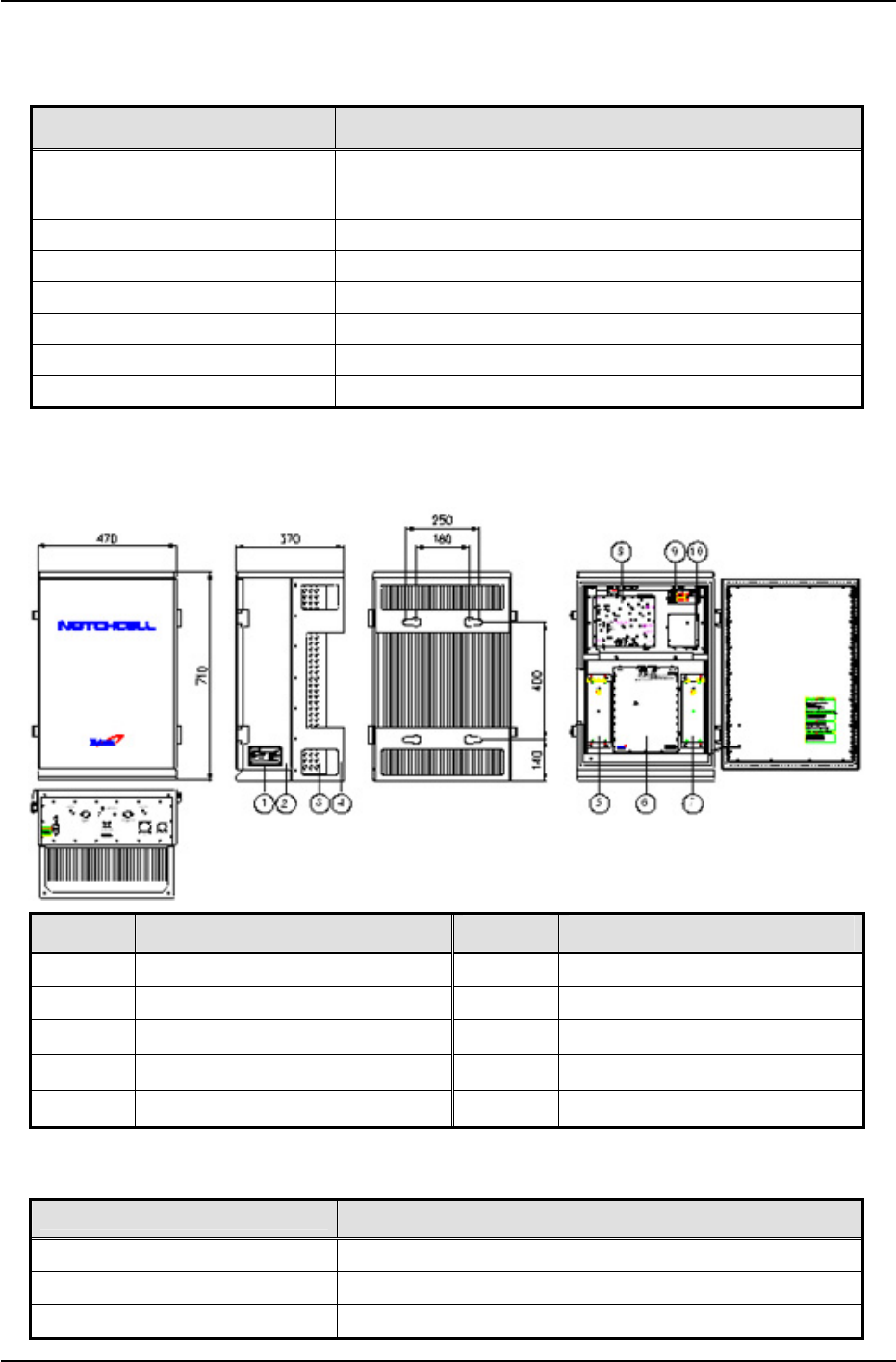
NO. Title NO. Title
1 Name Plate 6 DL Amplifier
2 Base 7 Duplexer(Mobile station)
3 Heat Sink 8 UDC(Up Down Converter)
4 MTG Bracket 9 DC/DC Converter
5 Duplexer(Base station)
10 UL Amplifier
Figure 3.1 Main box
ITEM SPECIFICATION
RF Connector N-female
Size (W x H x D) 710 X 470 X 370 mm / 27.95 x 18.50 x 14.57 inch
Weight Less than 50Kg / Less than 110 lbs
NOTCHCELL 20W OPERATING MANUAL
R-tron America, Inc. Page: 8 / 57
3.2.2.2 PSU box
NO. Title NO. Title
1 Name Plate 3 Heat Sink
2 Base 4 MTG Bracket
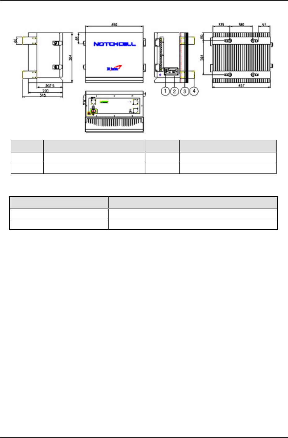
Figure3.2 PSU box
ITEM SPECIFICATION
Size (W x H x D) 450 X 385 X 315 mm / 17.72 X 15.16 X 12.40 inch
Weight Less than 25Kg / Less than 55lbs
NOTCHCELL 20W OPERATING MANUAL
R-tron America, Inc. Page: 9 / 57
3.2.2.3 Donor antenna
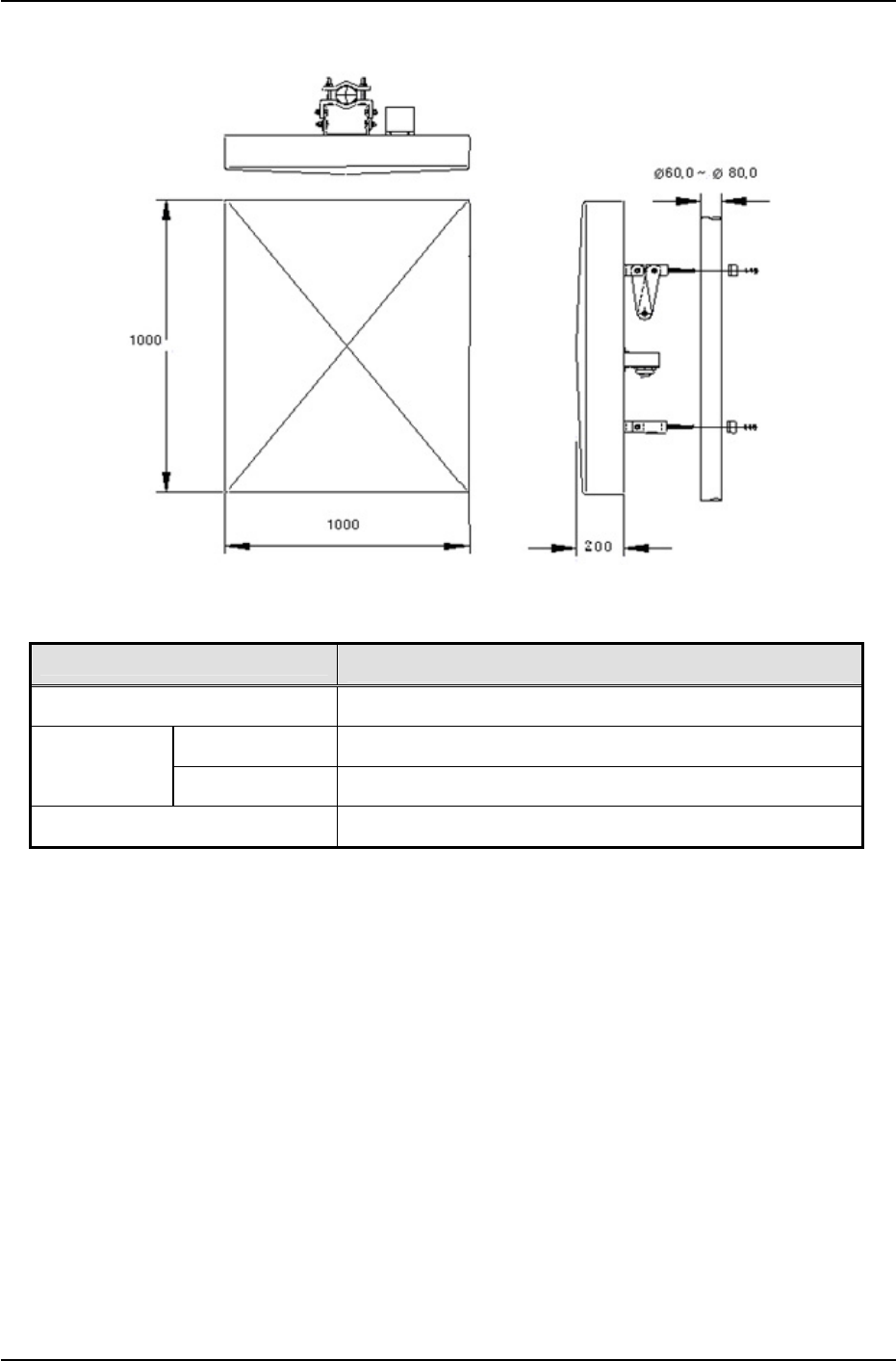
Figure3.3 Donor antenna
ITEM SPECIFICATION
RF Connector 1 X 7/16-female
Antenna 1020 X 675 X 116 mm / 40.16 X 26.57 X 4.57 inch
Size
(W x H x D) Shipping box 1130 X 785 X 270 mm / 44.49 X 30.91 X 10.63 inch
Weight Less than 20 kg / Less than 45 lbs
NOTCHCELL 20W OPERATING MANUAL
R-tron America, Inc. Page: 10 / 57
3.2.2.4 Distributor antenna
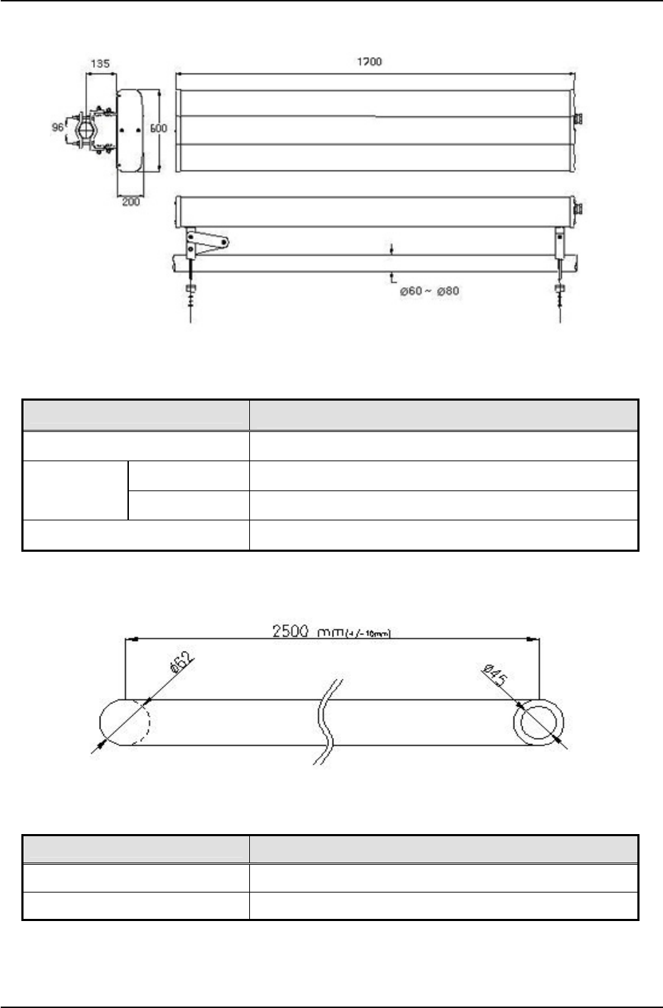
Figure3.4 Distributor antenna
ITEM SPECIFICATION
RF Connector 1 X 7/16-female
Antenna 1500 x 300 x 110 mm / 59.06 X 11.81 X 4.33
Size
(W x H x D) Shipping box 1560 x 320 x 190 mm / 61.47 X 12.60 X 7.48
Weight Less than 10 kg / Less than 22 lbs
3.2.2.5 Mount Pole (Option Item)
Figure3.5 Mount pole
ITEM SPECIFICATION
Length 2500 mm or 2900 mm / 98.43 or 114.17 inch
Weight Less than 6 kg / Less than 13.23 lbs

NOTCHCELL 20W OPERATING MANUAL
R-tron America, Inc. Page: 11 / 57
3.3 Installing information
3.3.1 Installation site
3.3.1.1 Right-of-way
- The repeater shall be installed in the location owned or leased by the carrier.
- If the repeater is installed on the roof, spaces for the installation must be considered.
3.3.1.2 Conditions for the Installation space
Installation of the repeater requires the following spaces.
1) Roof
Do not install the repeater near heavy equipments or water tanks for load distribution.
Establishes the repeater in order for the good air circulation of the rear side.
Make sure there is a passage for the equipments to carry the repeater.
2) Field
Select the installation location on a higher ground level to prevent the repeater from
being inundated.
Install the repeater at a distance of at least 5m from the stream or the river.
Make sure there is a passage and parking space for vehicle to carry the repeater.
Install the repeater in where there is no obstacle visually and physically.
Make sure to level the slope when installing on a slope in a mountain area.
3.3.1.3 Precautions
Check the followings before installing the repeater.
1) Roof
Avoid the location in which any accidental or intentional damage may occur.
Do not install the repeater on the weak slab.
Do not install the repeater on the building with the seriously damaged wall.
2) Field
Do not install the repeater on poor ground, sandy soil, or muddy ground.
Do not install the repeater in a ditch, river, or frequently flooded area.
Do not install the repeater on any locations that are easily frozen.
Do not install the repeater near the road.
Make sure to installation after securing safety facilities if installing it near the road.
Do not install the repeater in damp and humid areas.
Take proper measures against salt when installing the repeater in the coast.

NOTCHCELL 20W OPERATING MANUAL
R-tron America, Inc. Page: 12 / 57
3.3.1.4 Carrying and loading
Be careful not to cause any accident when loading the cabinet or carrying it to the
installation site and not to be damaged when handling it.
To prevent corrosion, carry the cabinet in silver vinyl or a wooden box.
Warning: To prevent all possible damage, do not unpack the box until the cabinet is
carried to the installation location.
Do not load excessive material on the top or cover of the packing.
3.3.2 Installing support
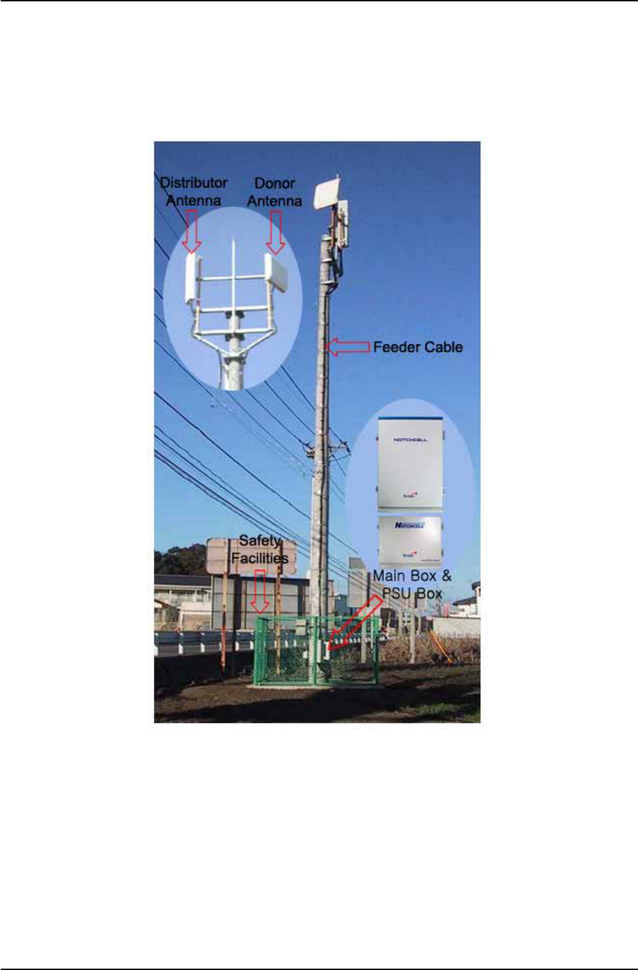
The RF repeater can be installed on a roof, an electric pole, or a large steel tower.
See the standard of the constructor for the installation on the steel tower or the electric
pole.
NOTCHCELL 20W OPERATING MANUAL
R-tron America, Inc. Page: 13 / 57
3.3.3 Installing the repeater
The installation methods of the repeater vary depending on the types of support (steel
tower), location, and demand of the carrier. This standard specifies the general
supporting methods and is subject to the types of support.
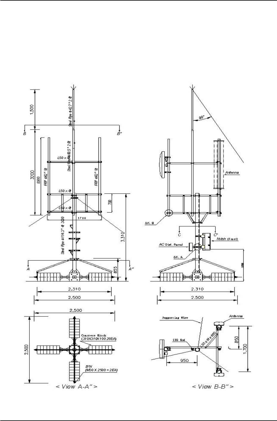
Figure3.6 Definition of assemblies (ex. electric pole)
3.3.3.1 General
- Check the level of ground when installing the repeater.
- Check if there is enough space for maintenance.
- If required, install branches to secure the safety of the steel tower.
- Fasteners must be melted and zinc plated.
- Use two nuts for a bolt to prevent the connection from becoming loose.
- If the repeater is installed too high, set up the safety scaffold.
NOTCHCELL 20W OPERATING MANUAL
R-tron America, Inc. Page: 14 / 57
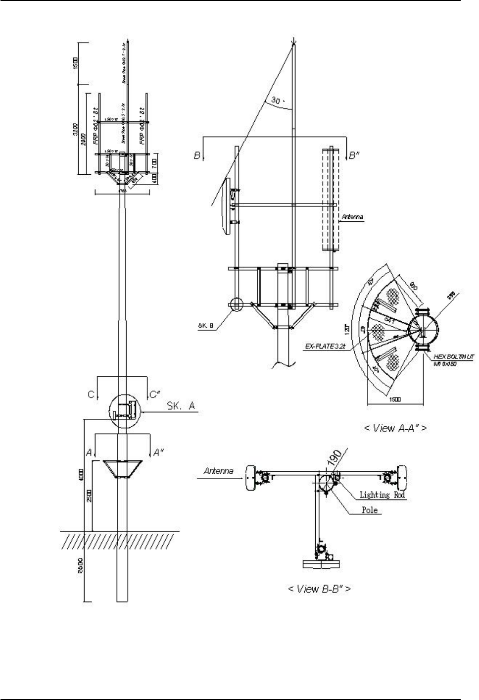
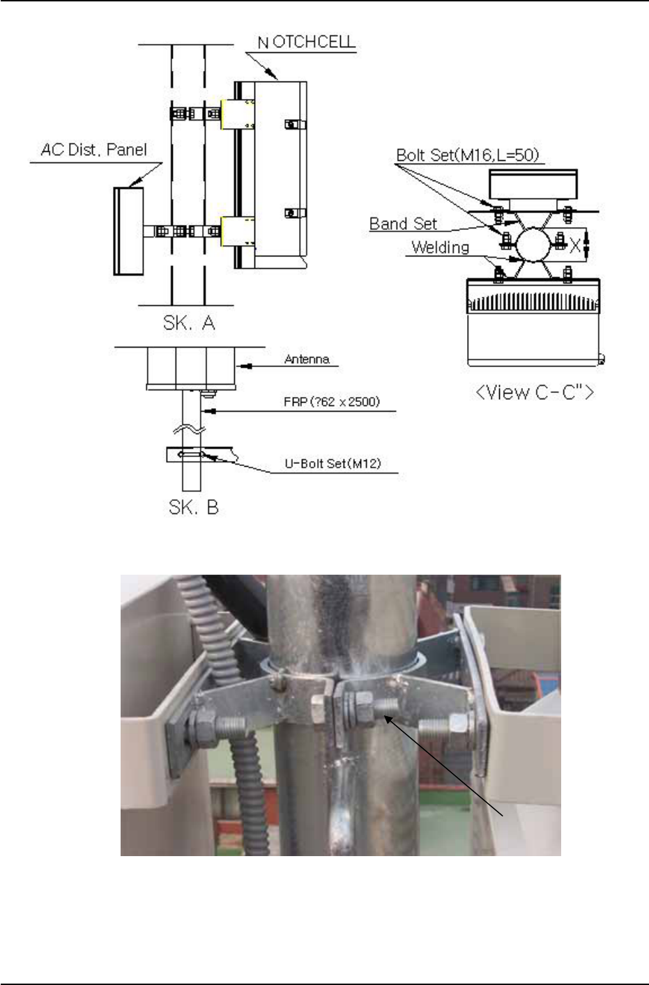
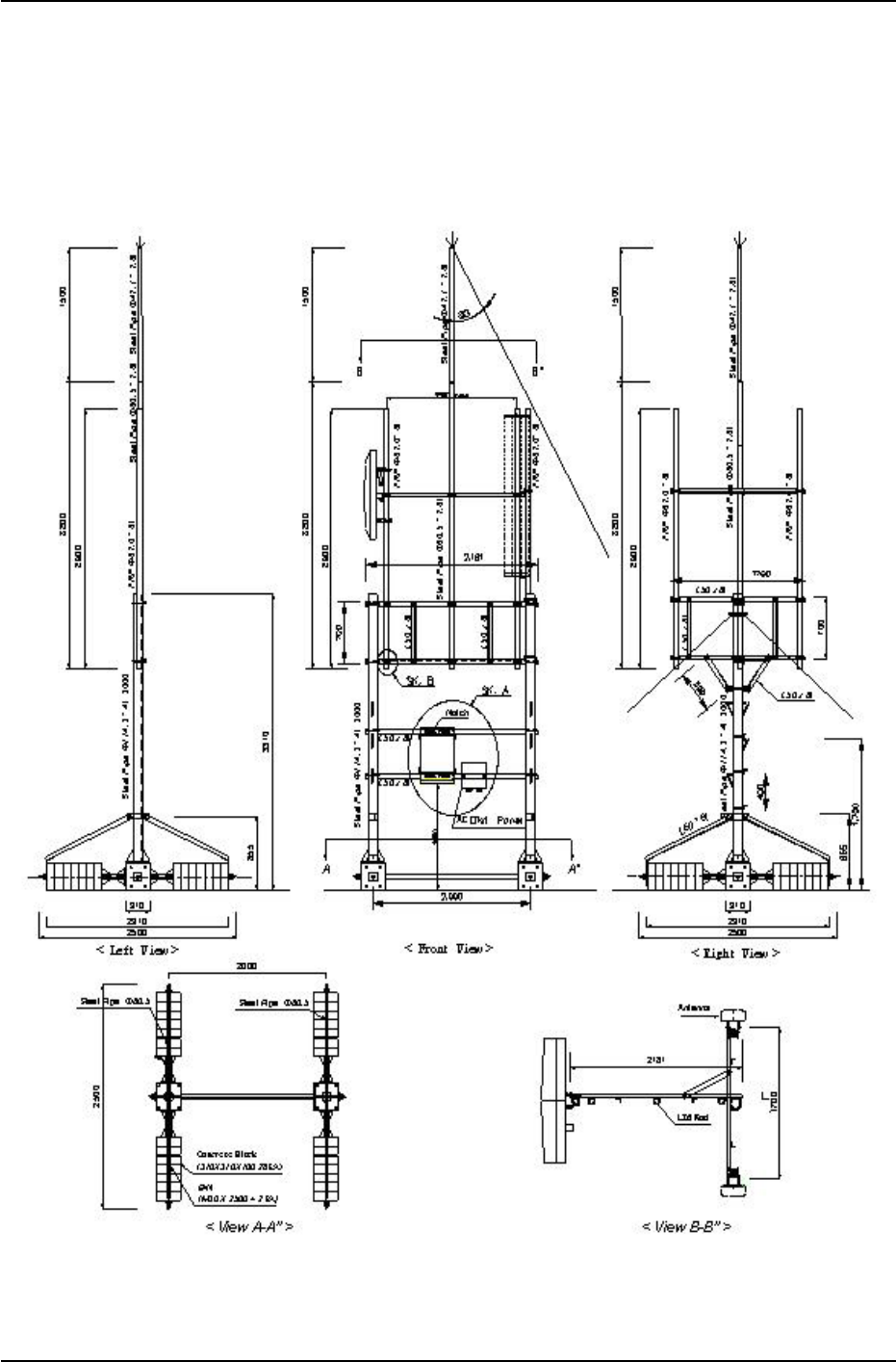
3.3.3.2 Installing band
- When installing the repeater on a cylindrical support such as steel pipe and steel pole,
manufacture and install the band in accordance with the size of the support.
- When installing the repeater on the roof, the standard height to the bottom of the
repeater shall be 1.2m.
- Install the AC distribution panel near the repeater or in the rear of the repeater.
Figure3.7 Band installation diagram 1 (steel tower type)
NOTCHCELL 20W OPERATING MANUAL
R-tron America, Inc. Page: 15 / 57
Figure3.8 Band installation diagram 2 (electric pole type)
NOTCHCELL 20W OPERATING MANUAL
R-tron America, Inc. Page: 16 / 57
Figure3.9 Band installation diagram 3 (location of repeater)
Figure 3.10 Band set
Band Set
NOTCHCELL 20W OPERATING MANUAL
R-tron America, Inc. Page: 17 / 57
3.3.3.3 Installing L-Type angle
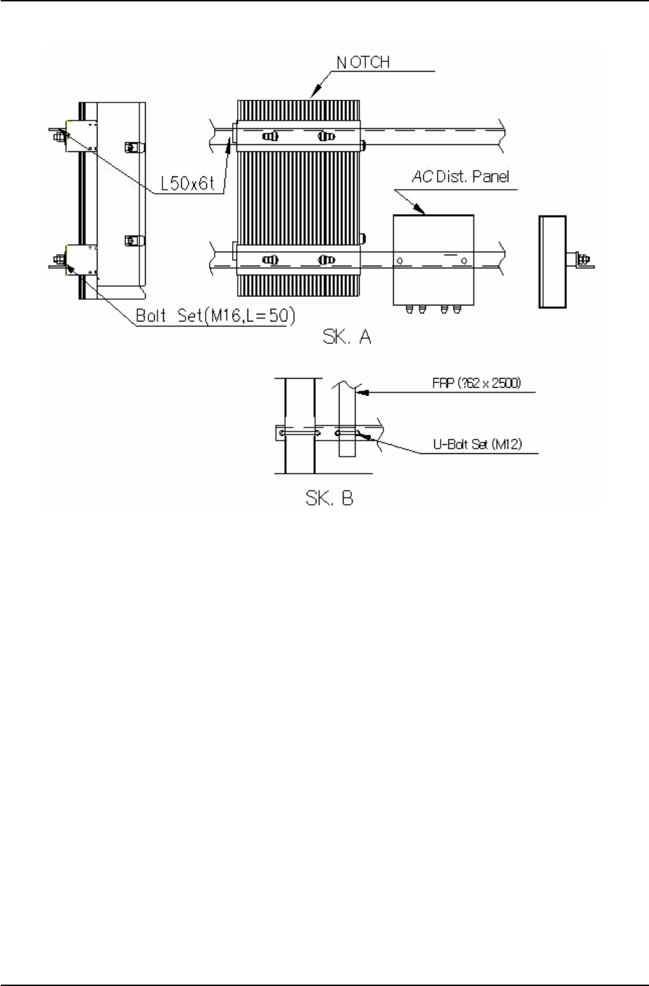
- The AC distribution panel shall be, in principle, on the left of the repeater.
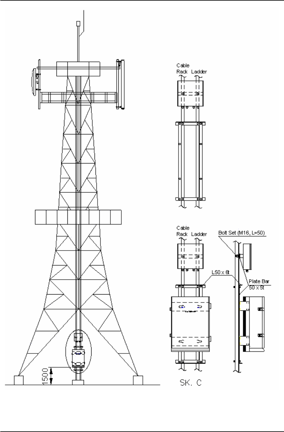
- When installing the repeater on the roof, the standard height to the bottom of the
repeater shall be 1.2m, and 4m when on a field.
Figure 3.11 L-Type installation diagram 1 (steel tower type)
NOTCHCELL 20W OPERATING MANUAL
R-tron America, Inc. Page: 18 / 57
Figure 3.12 L-Type installation diagram 2 (location of repeater)
NOTCHCELL 20W OPERATING MANUAL
R-tron America, Inc. Page: 19 / 57
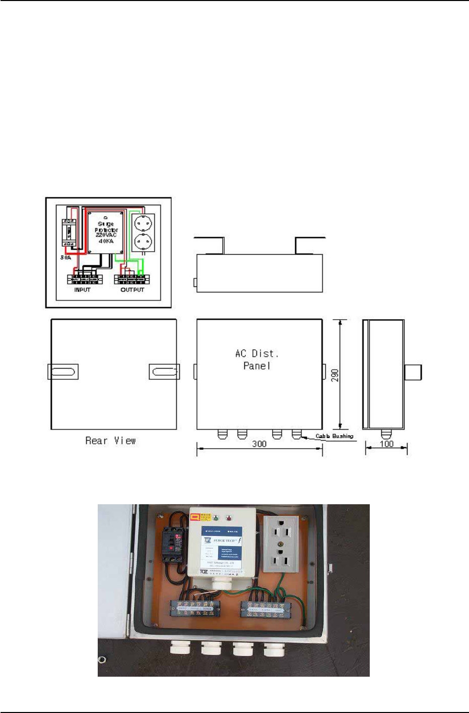
Figure 3.13 L-Type installation diagram 3 (steel tower type)
NOTCHCELL 20W OPERATING MANUAL
R-tron America, Inc. Page: 20 / 57
3.3.4 Installing AC power cable
3.3.4.1 AC distribution panel
Install the AC distribution panel on the steel tower to supply AC power to PSU of the
repeater.
1) AC distribution panel specification
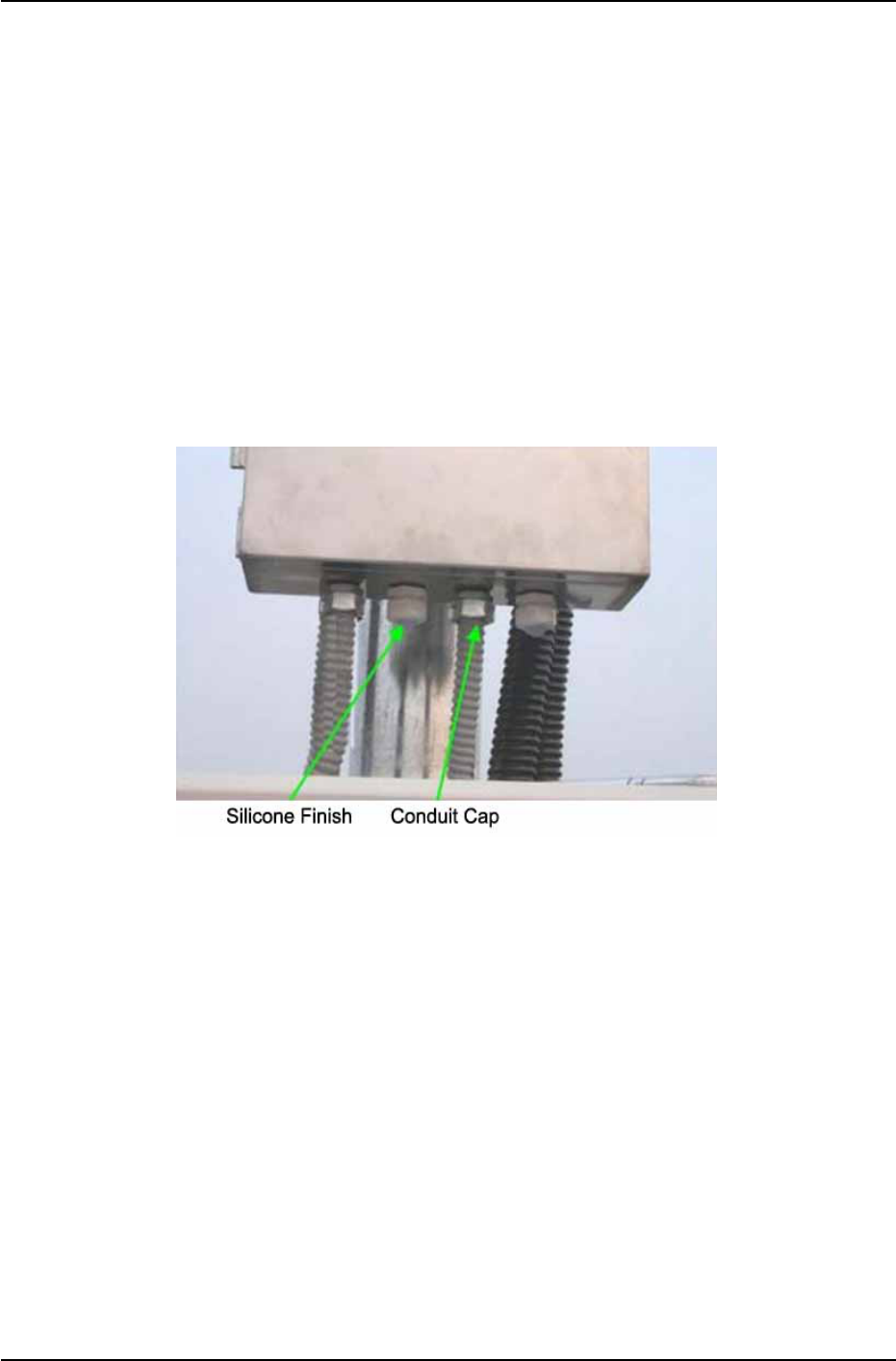
The AC distribution panel consists of a Breaker (30A), a Surge-Protector (40KA), a two -
hole outlet, and terminal blocks.
The cabinet shall be waterproof and equipped with cable bushings on the bottom.
See “Chapter 3.3.3 Installing the repeater” to install the AC distribution panel.
Figure 3.14 AC Distribution Panel Diagram 1
Figure 3.15 AC Distribution Panel Diagram 2
NOTCHCELL 20W OPERATING MANUAL
R-tron America, Inc. Page: 21 / 57
3.3.4.2 Installing AC power cable
- Connect the CV 5.5㎟ ~ CV 22㎟ x 2C power cable from the accumulative wattmeter
to the AC distribution panel with the Ring Type Terminal Lugs and Flexible Conduits.
- Use the Fork Type Terminal Lugs when connecting the AC power cable.
- No cable will have contact points inside the conduit, and distribution/connection shall
be allowed only in the AC distribution panel.
- Use 22mm flexible conduit when installing the power cable.
- Fix the conduit firmly on the wall or the ground with Saddle.
- Fill up the vacant cable busing holes on the AC distribution panel with silicon.
- Fit the end of the flexible conduits with the conduit caps or by taping.
- All the Flexible Conduits must be sealed tight.
Figure 3.16 Flexible Conduit End Fitting

NOTCHCELL 20W OPERATING MANUAL
R-tron America, Inc. Page: 22 / 57
3.3.5 Grounding
Three types of grounding are applied - system grounding, arrester grounding, and steel
tower grounding.
The arrester and the fixing studs are installed on the bottom of the repeater.
The steel tower grounding and arrester grounding shall be in conformity to the standard
of the steel tower manufacturer.
3.3.5.1 General
- Use the GV cable for the grounding.
- Branch point shall be finished with C-tap and the heat shrink tube. When branching off
outside, make sure to prevent the inflow of rain.
- Grounding shall be, in principle, connected from the Under Ground grounding.
- Install the grounding cable with PVC Flexile Pipe and Flexible Conduits for the external
protection.
3.3.5.2 System grounding
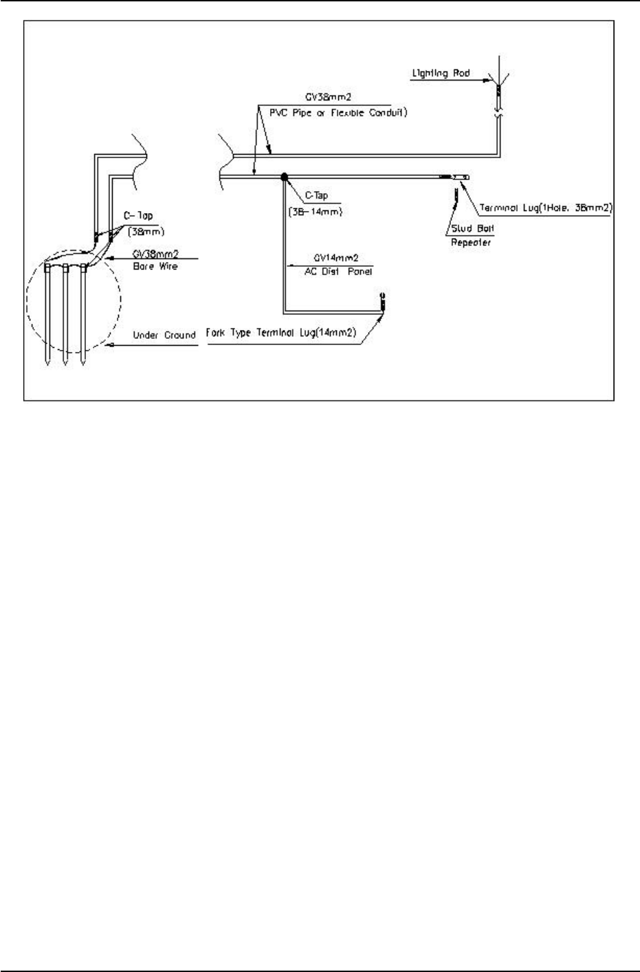
- The Under Ground shall be made with up to 3 ground bars or with ground resistance
of 20Ω or lower.
- After excavating the ground to 70Cm from the surface, cast the ground bars at a
distance of at least 3m between one another.
- Connect the ground bars to the PVC Pipe with Bare Wire(38㎟) and C-Tap.
- Connect GV 38㎟ x 1C to the stud on the bottom of the cabinet with the underground
bar.
- Use the 1 Hole Terminal Lugs, and finish with the Green Shrink Tube.
- For the arrester grounding of the steel tower, connect GV 38mm² x 1C from the Under
Ground
NOTCHCELL 20W OPERATING MANUAL
R-tron America, Inc. Page: 23 / 57
Figure 3.17 Ground Cable Diagram
3.3.5.3 AC distribution panel grounding
For Surge Protector ground of the AC distribution panel, connect GV 14㎟ cable to the
repeater cabinet grounding cable (GV 38㎟), branching it off with C-Tap (38-14mm).
Connect to the ground Terminal Block in the AC distribution panel with the Fork Type
Terminal Lug.
3.3.6 Installing the feeder cable
3.3.6.1 Installing the feeder cable
1) Connection between the antenna and the repeater
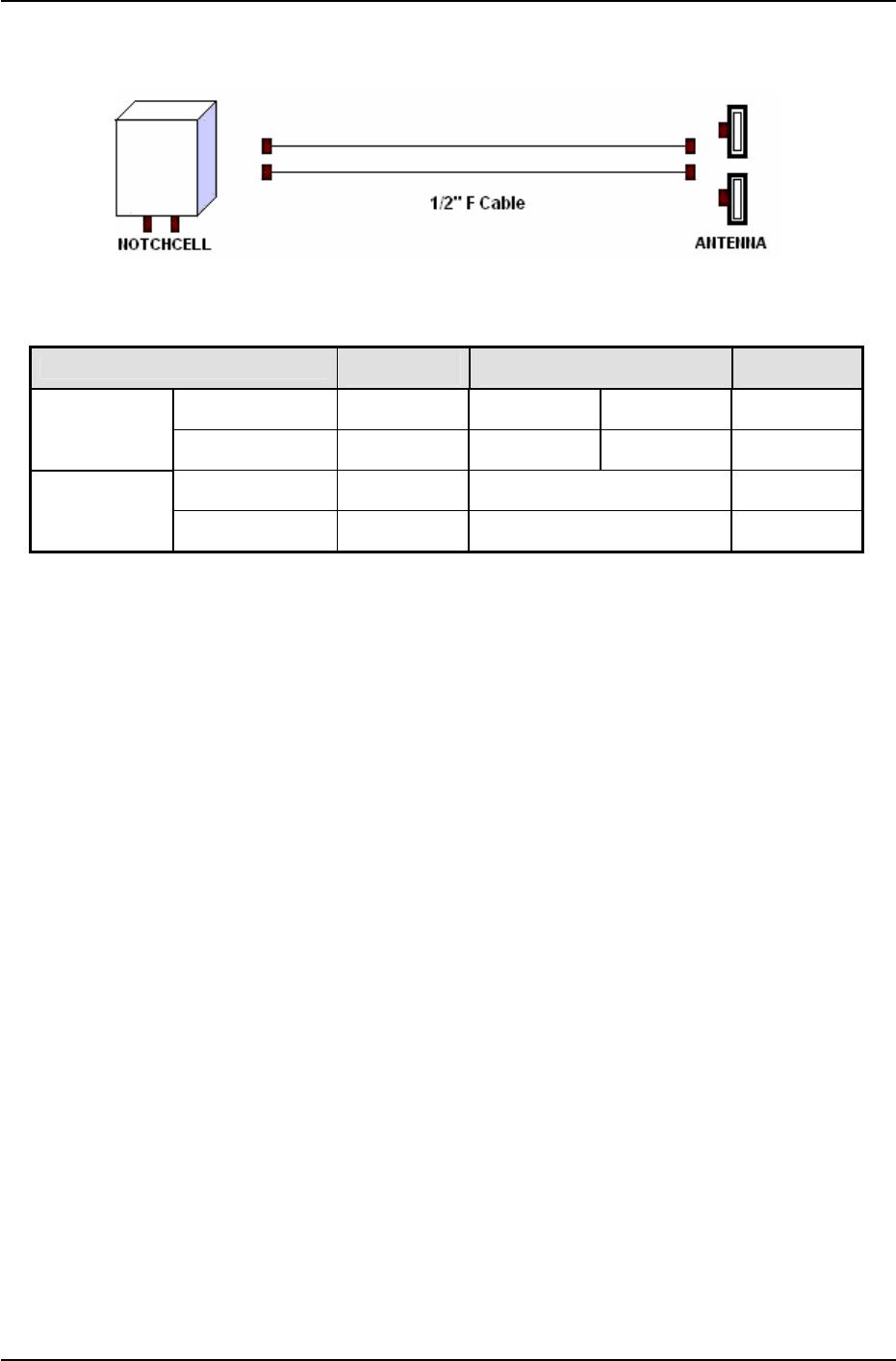
Use two RF Repeater Antennas.
Install a pair of 1/2” cable from the arrestor on the bottom of the repeater cabinet to the
Antenna.
The Standard of feeder cable between the Antenna and the repeater shall be
conformed to that of the carrier.
The Connector for the feeder cable and the connector for the 36mm Æ #36 Flexible
Conduit End Cap are installed on the bottom of the repeater and the RF Antenna.
NOTCHCELL 20W OPERATING MANUAL
R-tron America, Inc. Page: 24 / 57
2) Connecting the feeder cable connector
Figure 3.18 1/2”Feeder Cable Diagram
ITEM ARRESTER 1/2” F CABLE ANTENNA
Type N - Female N - Male N - Male N - Female
Connector
Quantity - 2 2 -
Type - 1/2” F Cable -
Feeder Cable
Weight Quantity - 2` -
3) Cautions in the installation of the feeder cable
Install the cable in the shortest distance, if possible, between the Antenna and the
repeater.
The selected cable path must not affect the appearance of the building or the station.
When installing the repeater in a general building, select the cable path in which the
feeder cable is not damaged by outsiders or other factors.
Select the feeder cable path with less curves and attach the feeder cable tag.
The VSWR in the power feeder must not higher than the standard at the completion of
the work.
Do not use the damaged feeder cable.
NOTCHCELL 20W OPERATING MANUAL
R-tron America, Inc. Page: 25 / 57
4) Installing/ tying the feeder cable
The installation of the feeder cable is sensitive to the bend radius and humidity.
Therefore, the following regulations shall be observed.
Maintain the minimum bend radius. (Higher than the standard presented by the
manufacturers)
The cable must not be entangled.
Do not apply excessive force to the feeder cable to prevent bent insulated conductors or
dug coverings.
The outer connecting part of the connector must be waterproof.
Tie the cable at every 50cm.
Tie the cables firmly so that they shall not be affected by external impact.
Use the bending machine if required to bend the cable.
Cut the feeder cable with a hacksaw and clean out the cut area.
5) Feeder cable connector
The followings shall be observed at the assembly of the feeder cable connector.
Cut the feeder cable carefully to prevent the inflow of water, steel and lead strip, or dust.
Clean the connector and the gasket connector to keep airtight.
Do not apply excessive force nor work in a hurry.
Avoid connection work at the time of rain. If it is unavoidable, be careful to prevent the
inflow of rain to the connecting part of the feeder cable connector.
All the connector parts must be waterproof.
Install the 1/2” feeder cable by inserting it into the shield cable and 36mm flexible
conduit. In case of the 7/8”feeder cable, install the cable only.
The installation of the 1/2” feeder cable is as follows
Cut the 1/2”feeder cable, Shield cable and 38mm Flexible Conduit in a necessary length.
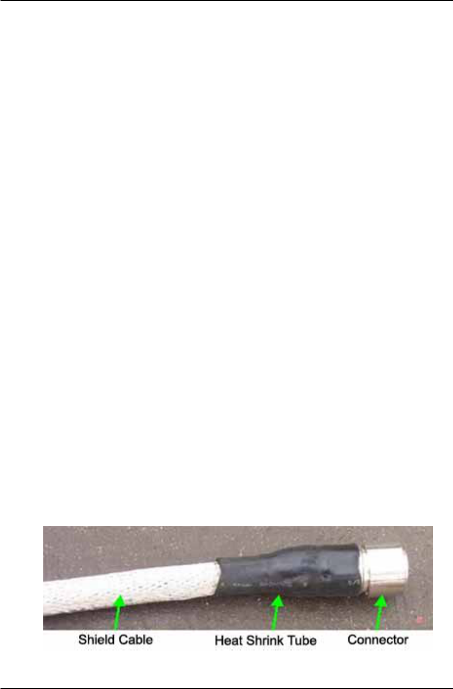
Insert 1/2”feeder cable into the Shield cable, and then assemble the connectors at both
ends.
Compress the Shield cable on the Antenna side with the Heat Shrink Tube.
Figure 3.19 Shield Cable and Connector
NOTCHCELL 20W OPERATING MANUAL
R-tron America, Inc. Page: 26 / 57
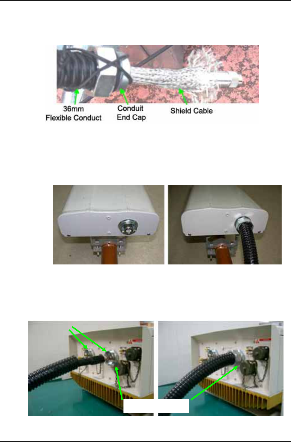
Assemble the Conduit End Cap (repeater accessory) at both ends of 36mm Flexible
Conduit.
Insert the assembled 1/2” feeder cable (shield cable) into the 36mm Flexible Conduit.
Figure 3.20 Feeder Cable at Repeater Side
After installing and tying the cable, connect the connector to the bottom of the antenna
and then apply the Conduit End Cap.
Figure 3.21 Connector on the Antenna Side
Compress the Shield cable on the repeater with the heat shrink tube.
Connect the feeder cable connector to the arrestor onto the bottom of the repeater, and
then apply the Conduit End Cap.
Figure 3.22 Installing the connector on the repeater side
Connector
Conduit End Ca
p

NOTCHCELL 20W OPERATING MANUAL
R-tron America, Inc. Page: 27 / 57
3.3.7 Installing Antenna
3.3.7.1 Precautions
Antenna is a precise material. Make sure of no damage or deformation on it through the
careful installation.
Do not apply excessive force nor work in a hurry.
The retainers shall be zinc plated.
Set the accurate direction of the antenna with the transit when setting up antenna
support and its installation direction.
Select the location where radiating or receiving the radio wave from the antenna is not
disturbed by neighboring buildings or other topographical features or where bad
influences can be excluded.
Select the location where the antenna is electrically isolated enough from spurious
wave or high voltage cable that may block the radio wave radiation or reception.
Load generated by the Antenna must be evenly distributed on the steel tower. It must
be also applied on the main material of the steel tower.
Each Antenna supporting bar must be fixed under the safety angle (60˚) of lighting rod.
3.3.7.2 Installing Antenna
Fix the Antenna firmly to stand against external impact and wind.
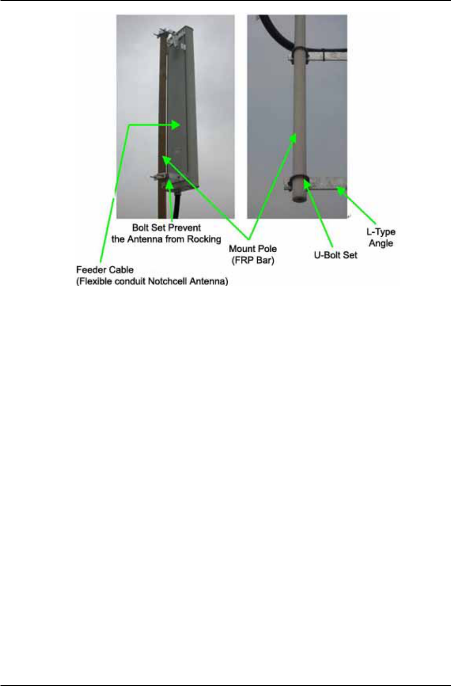
For isolation, FRP (Φ62x2900) shall be used as the Antenna fixing bar.
The Antenna shall be installed at a distance of minimum 1.5m from the Donor Antenna
and the Distributor Antenna.
Fix the Donor and Distributor antenna-fixing bar (FRP) onto at least 3 spots on the steel
tower with the U- Bolt
NOTCHCELL 20W OPERATING MANUAL
R-tron America, Inc. Page: 28 / 57
Figure 3.23 Antenna Installation
NOTCHCELL 20W OPERATING MANUAL
R-tron America, Inc. Page: 29 / 57
4. Operation
4.1 Isolation test procedure of Antenna
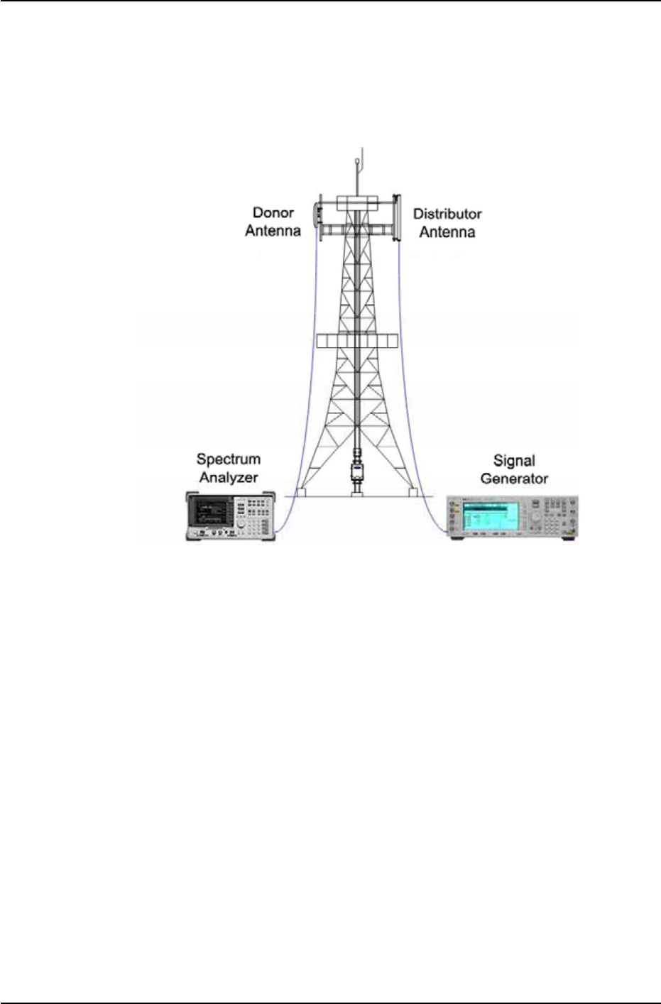
4.1.1 Isolation Measurement using for Signal Generator and Spectrum Analyzer.
Figure 4.1 Isolation test with S/G & S/A
The followings are isolation check procedures on the field site, using signal analyzer
and spectrum generator.
a Set-up the equipment as shown in Figure 4.1 Isolation test
b Set up the analyzer for the highest possible sensitivity (more than –100dBm) for
0 dBm source-power.
c Set the analyzer to “peak search mode “.
d After calibrated cable loss between Measurement Equip and Antenna, set the
output-power of the generator to 0 dBm.
e Turn on Signal Generator Output
f Measure the Antenna Isolation, using spectrum analyzer. The minimum isolation
is the highest value of the curve (excepting carriers transmitted by surrounding
BS).
g Change measurement-ports to check for the opposite direction by repeating the
measurement procedure.
h Repeat the test for the opposite path of the repeater. Step a to g.
*Isolation per carrier frequency is worse value.
NOTCHCELL 20W OPERATING MANUAL
R-tron America, Inc. Page: 30 / 57
4.1.2 Isolation Check using Isolation Check Menu
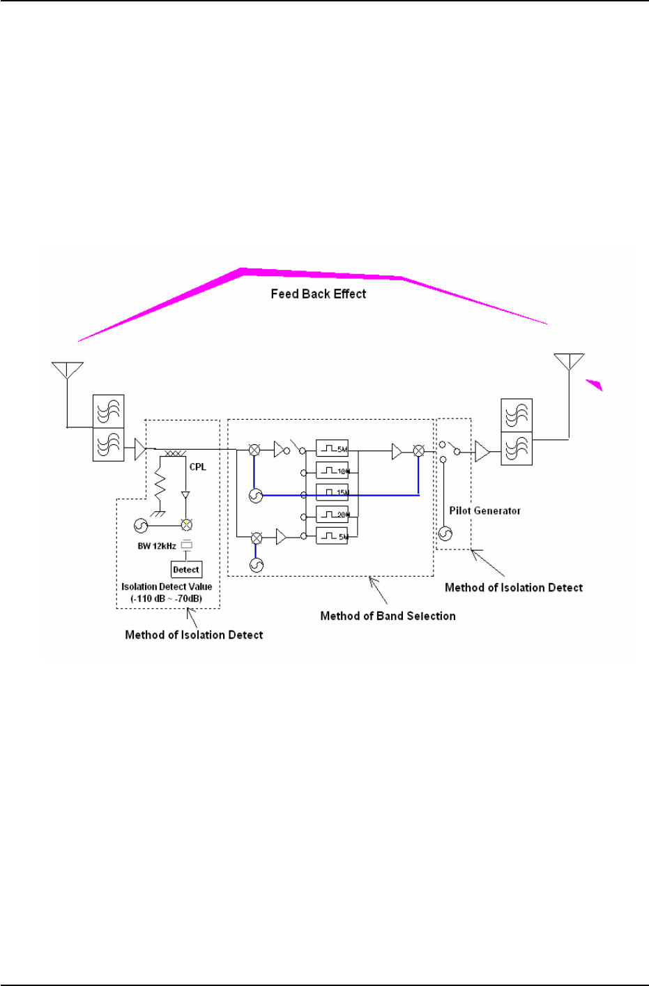
Notchcell 20Watt repeater isolation can be checked in the field without signal generator
and spectrum analyzer. Details are as followings.
1. Generate CW signal, using band guard pilot generator up link path(Repeater output
power : 30dBm)
2. Check power value which CW signal feeds back from donor to distributor antenna.
3. Isolation value = measured power value + output value 30 dBm
4. See more detailed measurement procedures at chapter 5.5.6 Isolation checking.
Figure 4.2 Isolation Check Block Diagram

NOTCHCELL 20W OPERATING MANUAL
R-tron America, Inc. Page: 31 / 57
5. Graphic User Interface
5.1 Introduction
This standards provides you how to install Notchcell 20Watts repeater software
which is programmable type and how to maintain it.
5.1.1 Compatibility
Notchcell programmable type GUI(Graphic User Interface) can be used regardless of
output power.
GUI program is based on windows 2000 or XP and the version of software and
firmware is as following,.
Product Software version Firmware version
NOTCHCELL 20W 1.1.0 1.1.1.0
NOTCHCELL 20W OPERATING MANUAL
R-tron America, Inc. Page: 32 / 57
5.2 Getting Started
5.2.1 Necessities
.
GUI software program
Computer
RS232 cable for Notchcell and PC connection
5.2.2 System Requirements
Windows 2000/XP Free serial port or
USB to RS232 converter
128 MB RAM 10 MB free space on hard drive
Pentium III processor monitor (minimum 1024 X 768)
Mouse, keyboard CD-ROM drive
5.2.3 Software Installation
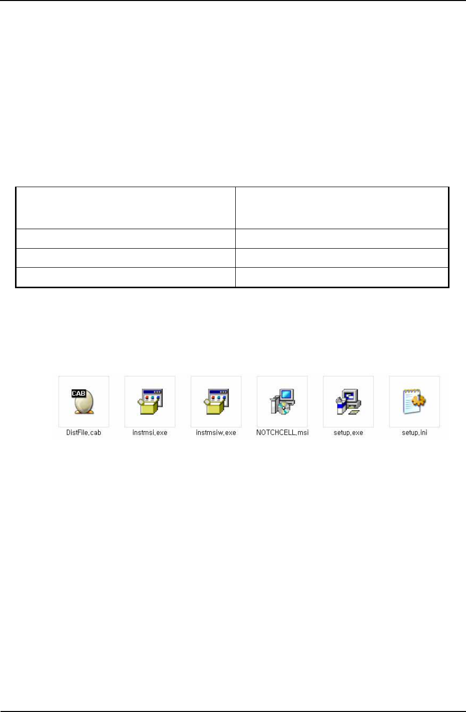
- To install GUI
1. Click “setup.exe” file which is in GUI program folder and then install GUI program.
Figure 5.1 GUI Program Folder
2. Follow the on-screen instructions.
GUI program will be installed at C:\Program Files\NOTCHCELL folder.
NOTCHCELL 20W OPERATING MANUAL
R-tron America, Inc. Page: 33 / 57
5.3 Connecting to the NOTCHCELL
5.3.1 Local Connection
How to setup a connection directly (local) to the Notchcell.
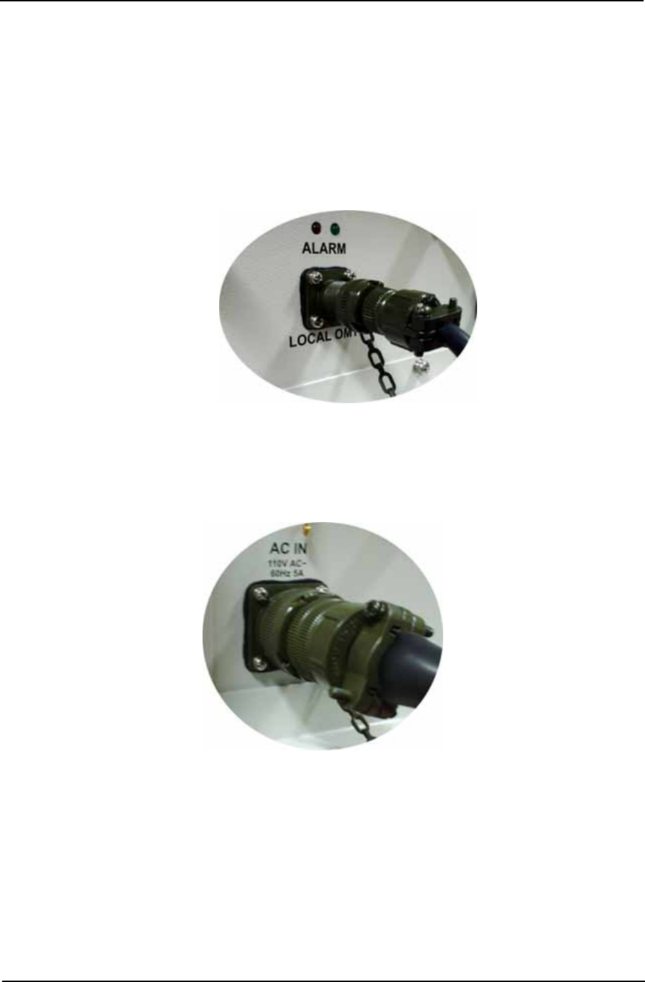
1. Connect RS232C cable with Notchcell “LOCAL OMT” port.
2. Connect adapter with PC serial port.
When it comes to USB, use USB to RS232C adapter.
Figure 5.2 Local connection
5.3.2 AC Power ON
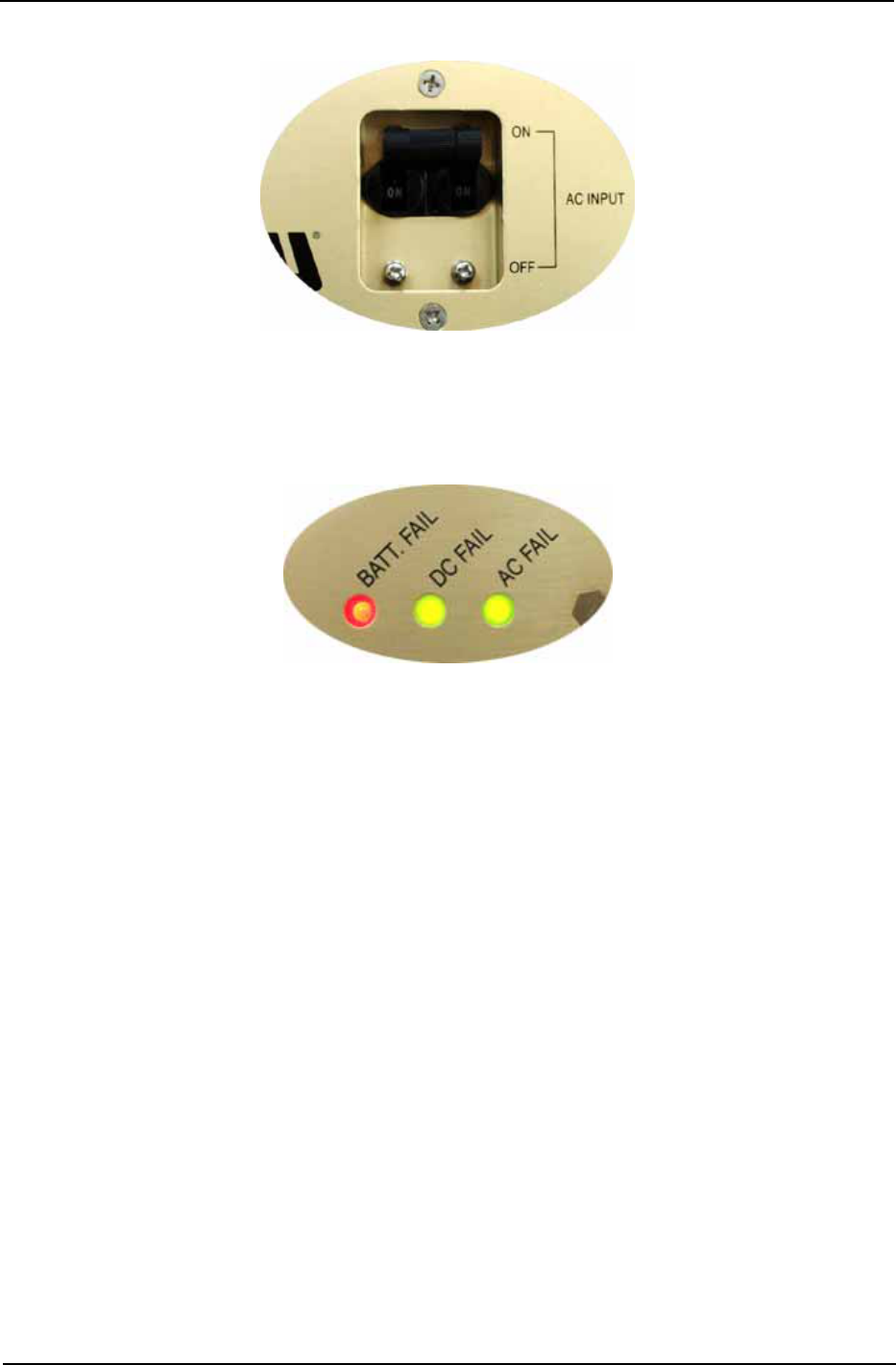
1. Check the status of Notchcell power cable connection.
Figure 5.3 AC Power cable connection
NOTCHCELL 20W OPERATING MANUAL
R-tron America, Inc. Page: 34 / 57
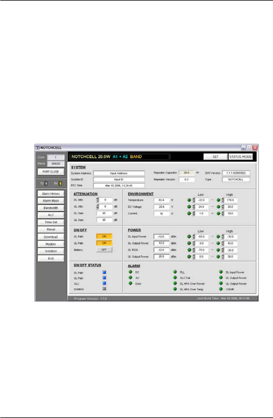
2. Open PSU box door and AC input switch as “ON” status.
Figure 5.4 AC Power ON
3. Check whether AC and DC fail LED color which is located in power supply unit
will be green or not.
Figure 5.5 Power Alarm LED
► Note : “BATT. FAIL” color will be green when battery properly connected with “DC
IN(24V)” and power supply unit “EXT. BATT. Input” switch should be “ON” status.
NOTCHCELL 20W OPERATING MANUAL
R-tron America, Inc. Page: 35 / 57
5.4 Setup & Status Mode System Displays
Notchcell GUI consists of “Setup Mode” which enables system control and “Status
Mode” which indicates system status. More details about GUI parameter, check
Appendix A – System Parameters.
5.4.1 Setup Mode
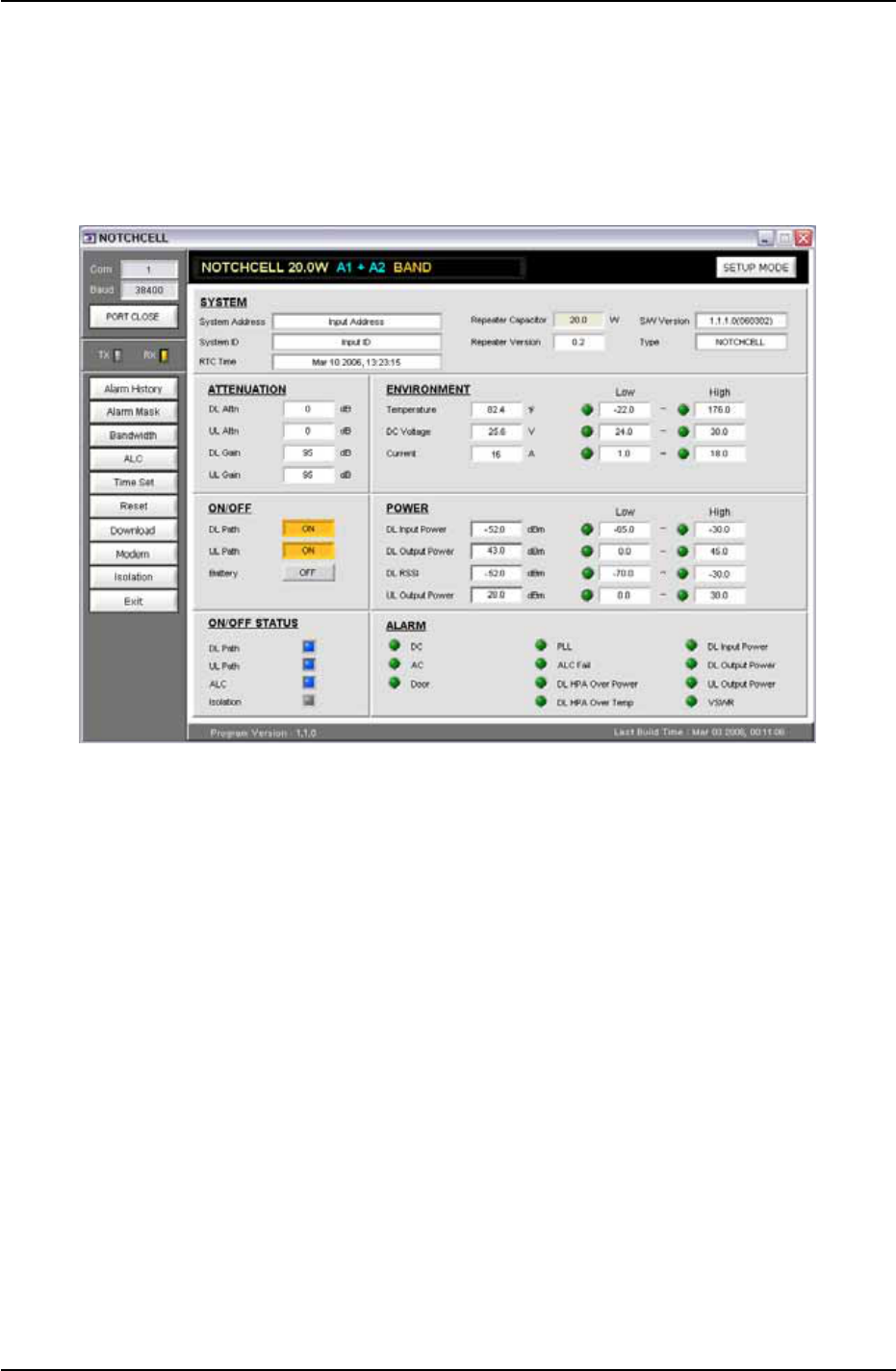
Repeater can be controlled in Setup mode. In Setup pop-up window, you can input
the value and control Bandwidth/Band, DL/UL Path, ALC, Shut down and attenuation.
When you are going to change the setting value, you should click “Set” button which
is in up-right side in the GUI screen.
Figure 5.6 Setup mode window
NOTCHCELL 20W OPERATING MANUAL
R-tron America, Inc. Page: 36 / 57
5.4.2 Status Mode
When you are going to check repeater status, click “Status mode” button which is in
the up-right side in the screen. And then check the value which is displayed in “Status
mode” and you can change output value, using attenuation value.
Figure 5.7 Status mode window
NOTCHCELL 20W OPERATING MANUAL
R-tron America, Inc. Page: 37 / 57
5.5 Repeater Set Using GUI
5.5.1 Executing GUI program
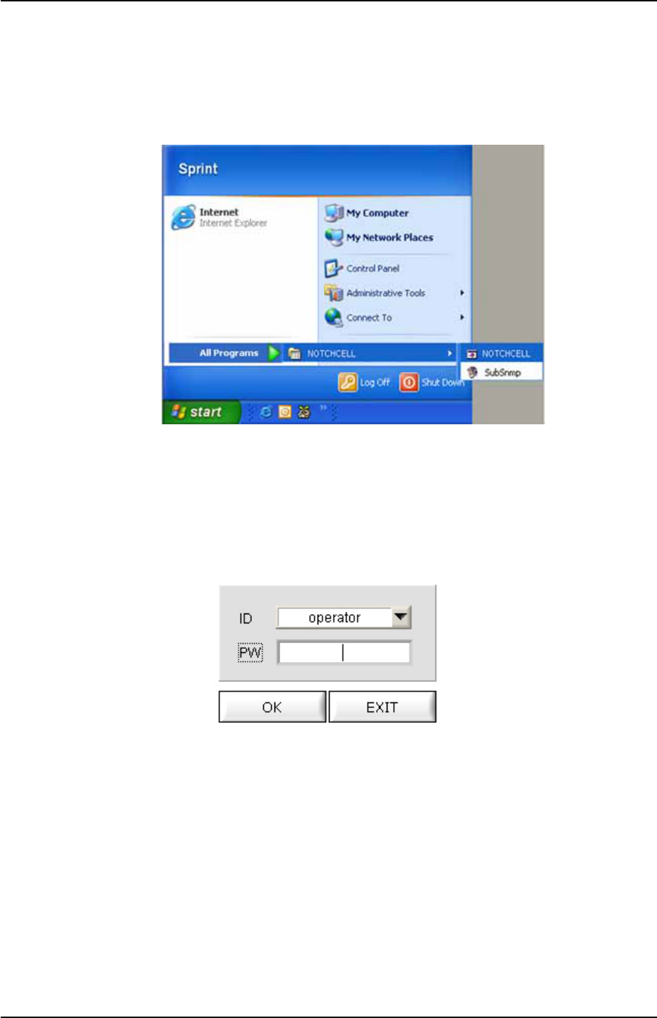
Execute Notchcell GUI program. (Installation details are in Chapter 5.2.3)
Figure 5.8 Execute GUI on Windows XP
5.5.2 User Check
When you execute GUI program, you can see login pop-up window.
(ID : operator / Password : spcs)
Figure 5.9 login pop-up window
NOTCHCELL 20W OPERATING MANUAL
R-tron America, Inc. Page: 38 / 57
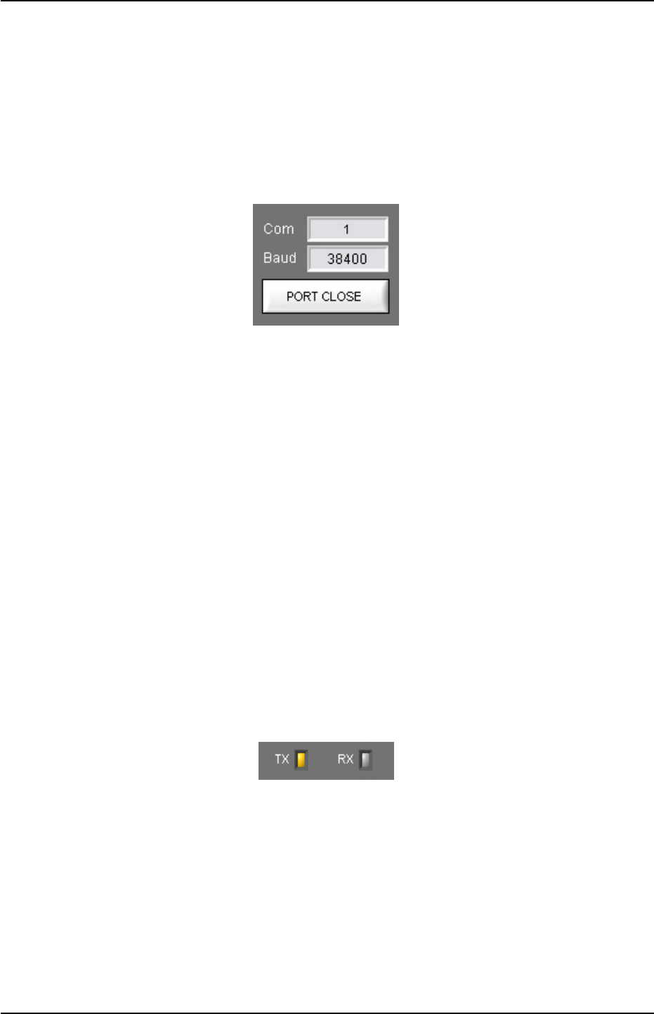
5.5.3 Communication Port and Speed Configuration
You should set the communication speed and port between your computer and
Notchcell for mutual communication.
User can set communication speed and port which control button is located upper
left-side in the main window screen. After that, communication is started.
(Communication Speed : 38,400 bit / second)
Figure 5.10 Communication Port and Speed Configuration
► Note : How to check computer communication port
1. Go to “Windows Control Panel”.
2. Go to “Function and Maintenance Management”
3. Go to “System”
4. Go to “Hardware”
5. Go to “System Management”
6. Go to “Port”
7. Check “Communication Port”
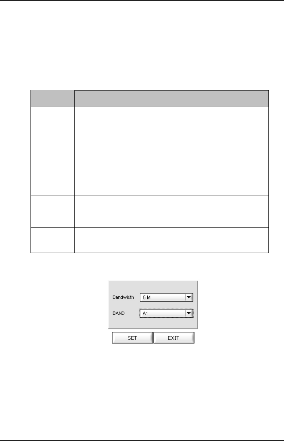
5.5.4 GUI Communication
When it is properly communicated between computer and repeater MCU board, Tx /
Rx yellow LED will be lit which is located the left-upper end in the GUI screen.
Figure 5.11 Communication Check LED
NOTCHCELL 20W OPERATING MANUAL
R-tron America, Inc. Page: 39 / 57
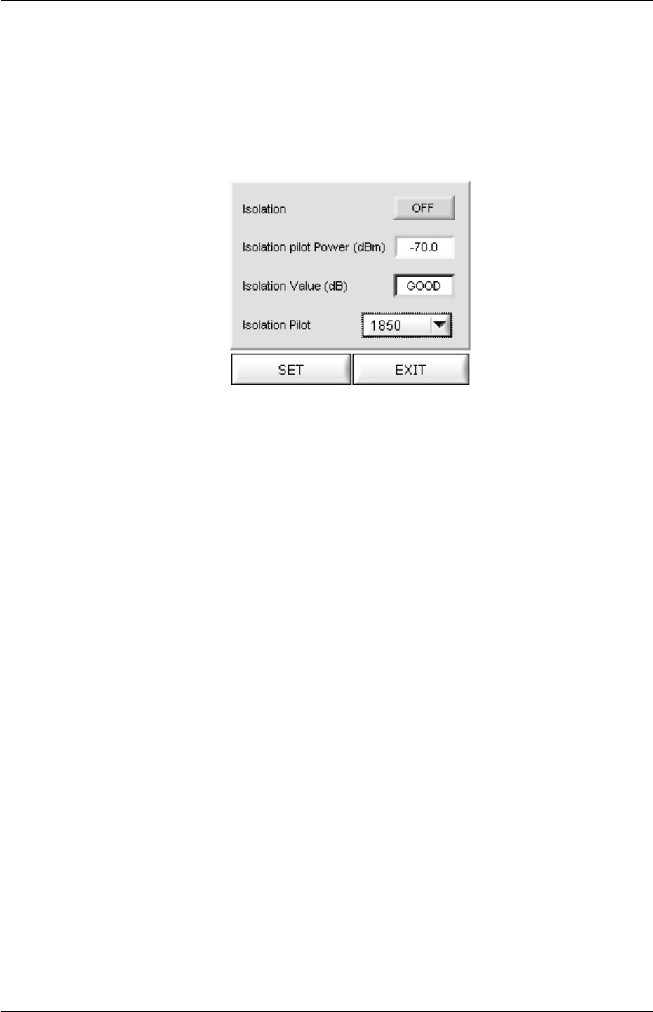
5.5.5 Bandwidth & Band Setting
When you click “Bandwidth” which is located left end in main window menu bar, you
can see bandwidth and band configuration pop-up window.
Then, set the band and bandwidth, considering the field condition. (See the following
table 5.1)
Bandwidth Band
5 MHz A1, A2, A3, D, B1, B2, B3, E, F, C3, C4, C5
10 MHz A1A2, A2A3, A3D, DB1, B1B2, B2B3,
B3E, EF, FC3, C3C4, C4C5
15 MHz A1A2A3, A3DB1, DB1B2, B1B2B3, B2B3E,
B3EF, EFC3, FC3C4, C3C4C5
20 MHz A1A2A3D, A2A3DB1, A3DB1B2, DB1B2B3,
B1B2B3E, B2B3EF, B3EFC3, EFC3C4, FC3C4C5
5+5 MHz
A1+D,A2+D,B2+D,B3+D,E+D,F+D,C3+D,C4+D,C5+D,
A1+E,A2+E,A3+E,DE.B1+E,B2+E,C3+E,C4+E,C5+E,
A1+F,A2+F,A3+F,D+F,B1+F,B2+F,B3+F,C4+F,C5+F
10+5MHz
A1A2+D, B2B3+D, B3E+D, EF+D, FC1+D, C3C4+D,
C4C5+D, A1A2+E, A2A3+E, A3D+E, DB1+E, B1B2+E,
C3C4+E, C4C5+E, A1A2+F, A2A3+F, A3D+F, DB1+F,
B1B2+F, B2B3+F, C4C5+F
15+5MHz
B2B3E+D, B3EF+D, EFC3+D, FC3C4+D, C3C4C5+D
A1A2A3+E, A2A3D+E, A3DB1+E, DB1B2+E, C3C4C5+E
A1A2A3+F, A2A3D+F, A3DB1+F ,DB1B2+F, B1B2B3+F
Table 5.1 Available Band and Bandwidth
Figure 5.12 Bandwidth Set Pop-up Window
► Note : How to set bandwidth
For example, you are in A1, A2 band,
① Click “Bandwidth” which is located in left end menu bar.
② According to the above table 5.1., band is A1, A2 10MHz bandwidth, select
“10M” as bandwidth.
③ Select ” A1+A2” in the band bar.

NOTCHCELL 20W OPERATING MANUAL
R-tron America, Inc. Page: 40 / 57
④ Click “SET” button to fix bandwidth and band.
⑤ Click “EXIT” button for exiting bandwidth pop-up window.
NOTCHCELL 20W OPERATING MANUAL
R-tron America, Inc. Page: 41 / 57
5.5.6 Isolation Checking
When you click “Isolation” button which is located left side menu bar, the following
pop-up window which is for isolation check between donor and distributor antennas
will be opened. “Isolation pilot power” value stands for isolation antenna value.
Figure 5.13 Isolation checking window
► Note : How to check isolation.
① Considering your location, check whether the repeater bandwidth and band
are properly set.
② Select “Isolation” in the menu bar.
③ Set “Isolation Pilot” value as UL path frequency which is used in the field.
④ Click “Isolation” button and make it as “ON” status. Then, click “SET” button.
⑤ The value which is in isolation value pop-up window is current system isolation
value.
- When isolation value will be over 110, it is displayed as “Good”.
When it is under 75, it is displayed as “Bad”.
From 110 to 75, isolation value will be displayed.
⑥ Following the above procedures, you should set the isolation only one time.
NOTCHCELL 20W OPERATING MANUAL
R-tron America, Inc. Page: 42 / 57
5.5.7 Gain & Attenuation Value Setting
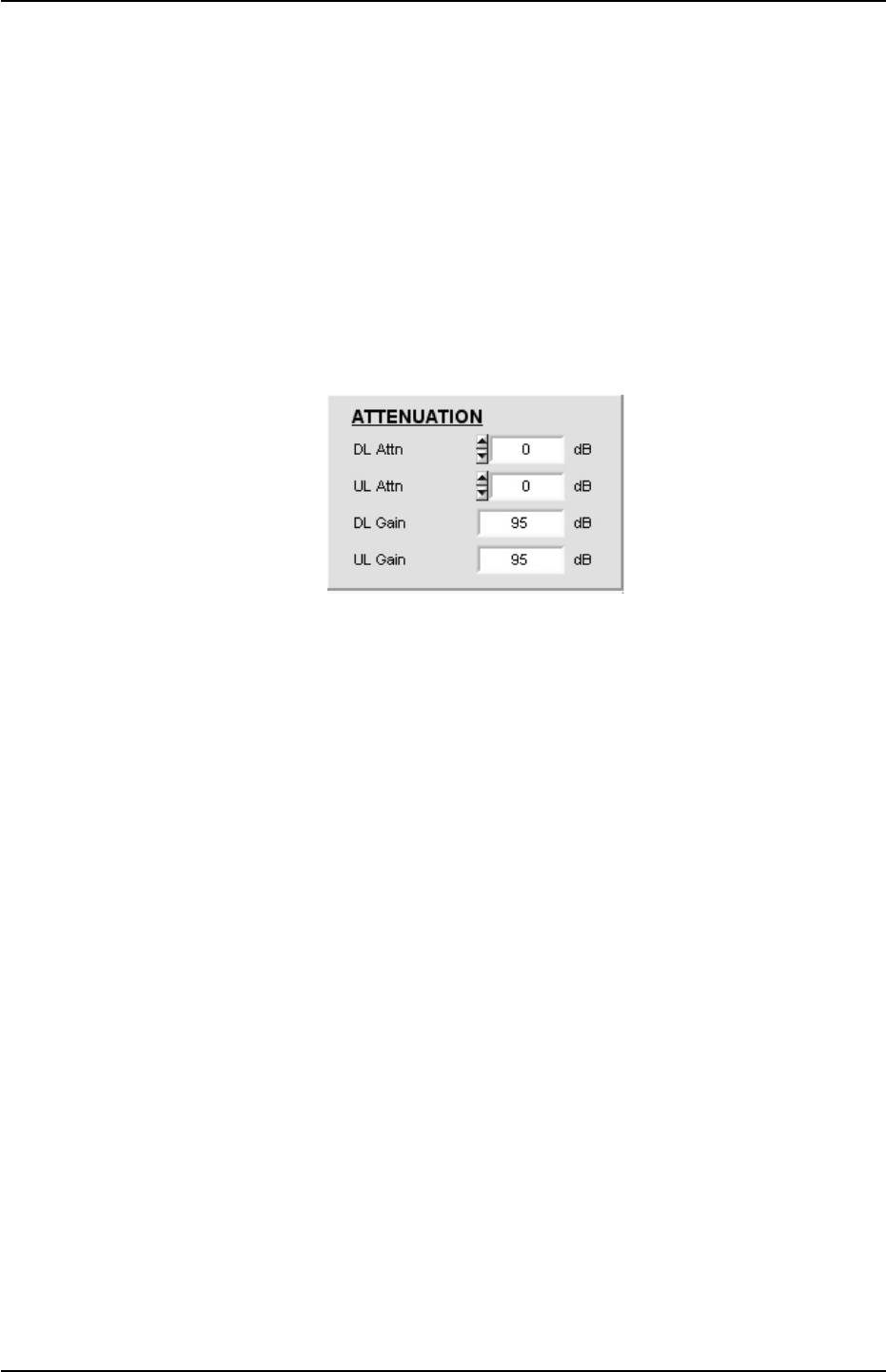
Following the above 5.5.6 isolation value setting, repeater gain can be set like below.
Maximum repeater gain is 95dB.
You can set attenuation value, controlling DL / UL ATTN. value which you are going
to be output value.
- Maximum Gain(dB) = Isolation Value(dB) – Margin (Margin ≥ 15dB)
- Repeater Gain(dB) = User’s targeting Repeater Output
Power(dBm) - Input power(dBm)
- Attenuation Value(dB) = 95(dB) – Repeater Gain(dB)
Figure 5.14 Gain setting window
► Note : How to set gain & attenuation value
Example 1) Field isolation value is 100. Down Link Path repeater input value
is -55dBm. User’s target output is 30dBm.
① Maximum available gain = 100(dB)–15(dB) = 85dB
Therefore, maximum gain value is 85dB.
② Repeater Gain setting :
Repeater Gain(dB) = 30(dBm) – (-55(dBm)) = 85(dB)
When an user is going to use output 30dBm, repeater gain needs 85dB.
③ Attenuation Value setting :
Attenuation Value(dB) = 95(dB) – 85(dB) =10(dB)
Set “DL Attn” value as 10 in the GUI and click “SET” button which is located
up-right end. On status mode, you can check “DL Attn” value is 10 and “DL
Gain” value is 85.

NOTCHCELL 20W OPERATING MANUAL
R-tron America, Inc. Page: 43 / 57
Example 2) Field isolation value is 100. Repeater input value is -65 dBm.
User’s target output is 30dBm.
① Maximum available gain = 100(dB)–15(dB) = 85dB
② Repeater Gain setting :
Repeater Gain(dB) = 30(dBm) – (-65(dBm)) = 95(dB)
Current input level -65dBm. Therefore, when an user is going to use output;
30dBm, repeater gain needs 95dB. Considering maximum repeater
gain;85dB, you can not set 30dBm as repeater output value.
► Note : Taking the above example 2, how to use repeater output as 30dBm.
① Change the direction of donor antenna for better input signal.
(minimum -55dBm)
② Set antennas isolation value as 110.
NOTCHCELL 20W OPERATING MANUAL
R-tron America, Inc. Page: 44 / 57
5.5.8 ALC(Auto Level control) & Shut-Down Setting
When you click “ALC” button which is located in left side menu bar, ALC, shutdown
set and ON/OFF control pop-up window will be displayed.
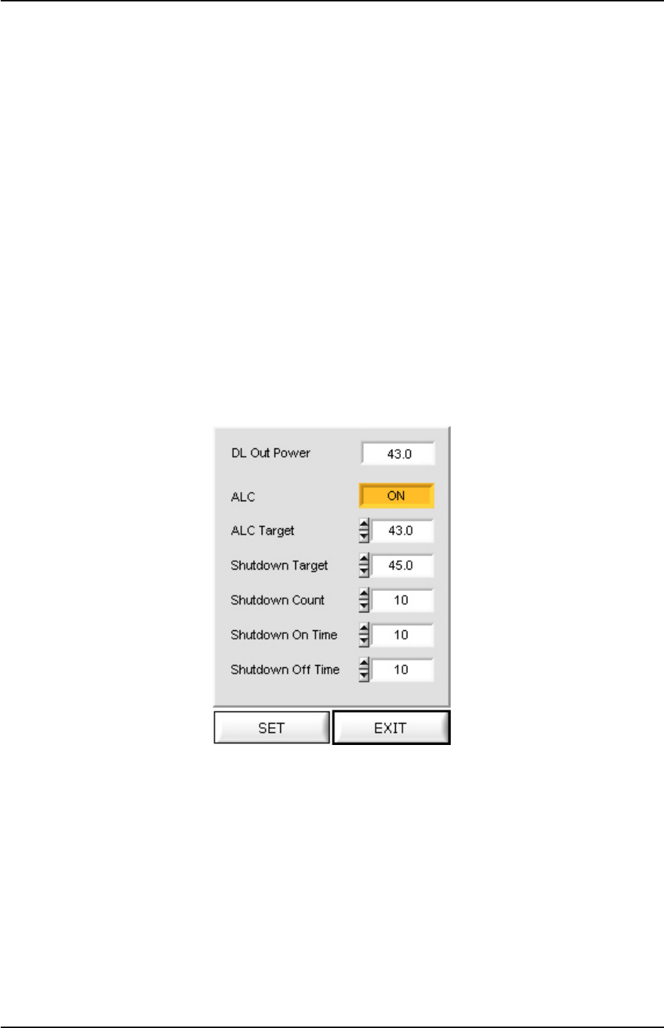
In the pop-up window, you can set downlink path output power like the above 5.5.7.
When DL output value will be over than shutdown target set value, the repeater will
be shutdown.
Normally, shutdown target value will be set 3dB higher than ALC target value.
About how to set shutdown count, shutdown on time and shutdown off time, please
refer it to Appendix A, Chapter A.2.4. ALC.
After input the value, click “SET” button for confirmation which is located in down side
in the ALC Set pop-up window.
Figure 5.15 ALC Set Pop-up Window

NOTCHCELL 20W OPERATING MANUAL
R-tron America, Inc. Page: 45 / 57
► Note : How to set ALC / Shutdown Target Value.
① When user set downlink path output power is 40dBm :
About ALC, DL output power value is 40dBm. Therefore, set ALC target value
as 40.
② Normal field situation, shutdown target value will be 43, 3dB higher than ALC
target value.
► Note : How to work ALC and ASD
If the ALC gets activated with system output exceeding ALC Target values, you
need to use the USER ATT to adjust the output to meet the range of the upper
settings. If the output exceeds the Attenuation range (30dB), the ALC FAIL alarm
will occur. If the system output exceeds the Shutdown Target value due to lack of
attenuation, then the ASD (Auto Shut Down) will be activated.
If output exceeds the Shutdown target values and makes the repeater shut down,
the repeater goes back to the active status after the ‘Shutdown-on’ time. If the
output of the repeater is higher than the set target value, the repeater will be de-
activated again after the set ‘Shut down-off’ time.
The repeater repeats the process by the Shutdown count. If the output of the
repeater still exceeds the target value after the repetitive work, the repeater will
turn completely off.
NOTCHCELL 20W OPERATING MANUAL
R-tron America, Inc. Page: 46 / 57
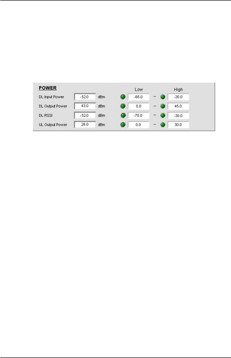
5.5.9 How to Set Alarm Range
Set input / output RF power maximum and minimum value of Down Link/Up Link.
When you are going to change the value, input the value and click “SET” button
which is located in up side control pop-up window.
You can check down link and up link input / output values at status mode.
Figure 5.16 Controlling Input/output
► Note : How to set Alarm range
* We would like to recommend you how to set alarm range as followings,.
① Make the gap between downlink path input power value and downlink input
power alarm range will be 5dB.
For example, when input power is -50dBm, alarm range will be from -55 to -
45dBm.
② Make the gap between downlink output power and downlink path output
power value will be 3dB.
For example, when output power is 30dBm, alarm range will be from 27 to 33
dBm.
③ Uplink output power alarm range will be from 0 to 30 dBm.
NOTCHCELL 20W OPERATING MANUAL
R-tron America, Inc. Page: 47 / 57
5.5.10 Modem Setting
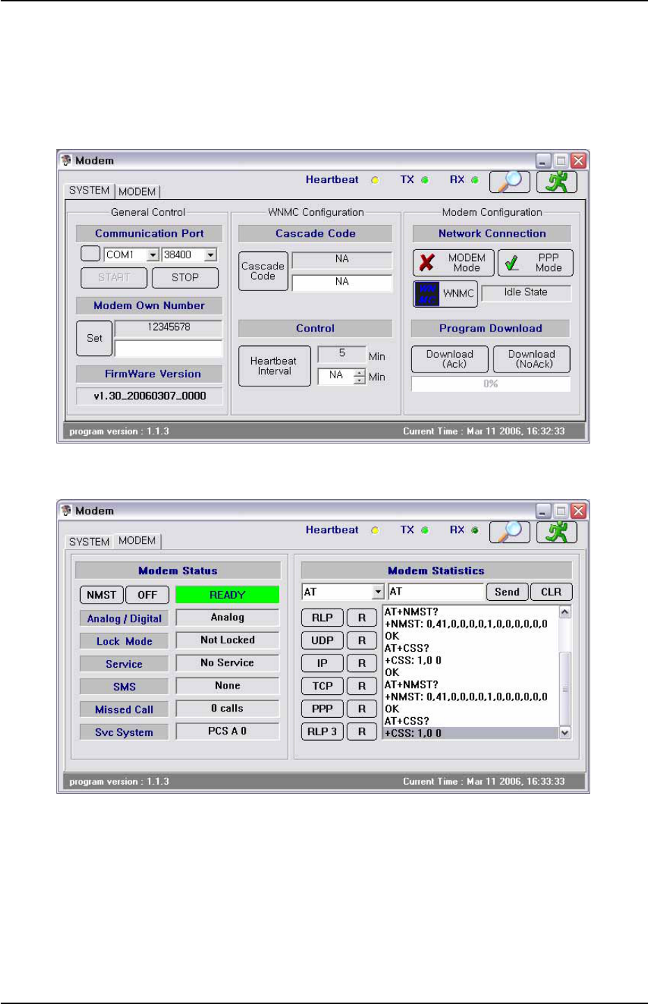
When you click “Modem” button which is located in left side menu bar, you can see
the following picture for basic modem set.
Figure 5.17 Modem System Window
Figure 5.18 Modem Status Window

NOTCHCELL 20W OPERATING MANUAL
R-tron America, Inc. Page: 48 / 57
► Note : How to check whether wireless modem properly works.
① Click “Modem” which is located in left side menu bar.
② When you see pop-up window like figure 5.17, make communication port
configuration same as GUI setting.
③ Click “START” button.
④ Check every parameters are same as your target value.(You can see more
details at appendix B B1.4)
- Modem Own Number : This is own number of WNMC (Wireless Network
Management Center) and your modem can make a phone call with this
number.
- Cascade Code : This is ID where the repeater is installed.
When the set value should be changed or updated, input new proper system value in
cascade code and click “SET” button. After that, site ID will be newly updated and
update confirmation pop-up message will be displayed.
- Control(Heartbeat Interval) : Controller periodically sends its information to
WNMC. We call it “Heartbeat”. Heartbeat time gap can be set from 3 to 59
minutes.
⑤ Click “Modem” button which is located in left side of modem system window.
⑥ Click “NMST” button.
⑦ Check “Ready” button will be activated as green color which is beside “NMST”
button.
⑧ Check modem status parameters. When displays are same as the followings,
it means that wireless modem setting is OK.
Analog / Digital Digital
Lock Mode -
Service In Service
SMS -
Missed Call -
Svc System PCS + Band Name + Numeric 4 or 5 Digits
NOTCHCELL 20W OPERATING MANUAL
R-tron America, Inc. Page: 49 / 57
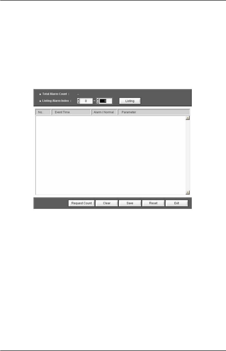
5.5.11 Default Alarm History
When an alarm is happened, alarm type and time are recorded in the alarm history.
To save repeater status check time, you can delete all alarming history for next
default setting.
More detail alarm history window parameters are in appendix A, Chapter A.2.1.
Figure 5.19 Alarm History Window
► Note : How to delete alarm history
① Click “Alarm History” button in the menu bar.
② Click “Reset” button for all deletes.
③ Click “Request Count” button and check whether alarm history is completely
deleted or not.
5.5.12 Repeater Reset
Click “Reset” button in the menu bar and check whether the repeater is properly
operated or not.

NOTCHCELL 20W OPERATING MANUAL
R-tron America, Inc. Page: 50 / 57
Appendix A. System Parameters
A.1 System state window
On the top side of GUI, repeater model name, current bandwidth and band are
displayed. On the left side, there are “SET MODE” and “STATUS MODE” buttons.
A.1.1 SYSTEM
System Address : Indicates where the repeater is installed.
System ID : Allocated number from base station. (from 0 to 16383)
For example, when PCS & A band system ID is 0, Service will be indicated as “PCS
B 0”.
RTC Time: Display current time which currently set in MCU.
When repeater time is incorrect, you can change it correctly, using Time Set in the
menu bar.
Repeater Capacitor : Repeater output
Repeater Version : H/W version
S/W Version : Repeater program(firmware) version
Type : Repeater type
A.1.2 ATTNUATION
DL / UL ATTN : On “SET Mode”, user can set downlink & uplink path attenuation.
DL / UL GAIN : On “STATUS Mode”, user can check DL/UL attenuation system
gain which is set on “SET Mode”
A.1.3 ENVIRONMENT
Env. Temp. : It displays system temperature.
DC Volt : It displays voltage status of power supply unit.
Current : It displays using system current volume
Battery Volt : It displays voltage status of power supply unit

NOTCHCELL 20W OPERATING MANUAL
R-tron America, Inc. Page: 51 / 57
A.1.4 ON / OFF
DL / UL HPA : Downlink and uplink power amplifiers ON / OFF.
Battery : Battery ON / OFF(Battery is optional)
A.1.5 POWER
DL In Power : Set alarm range and display downlink path input power.
DL Out Power : Set alarm range and display downlink path output power.
UL Out Power : Set alarm range and display uplink path output power.
A.1.6 STAUS (ON / OFF)
DL / UL Path : It displays the status of system DL/UL path. Path on status is blue,
off status is grey color.
ALC : It displays ALC operation status. ALC on status is blue, off status is grey color.
Isolation : It displays isolation operation status. Isolation on status is blue, off status
is grey color. When isolation “ON” status, UL path turns automatically “ON” status.

NOTCHCELL 20W OPERATING MANUAL
R-tron America, Inc. Page: 52 / 57
A.1.7 ALARM
DC / AC Alarm : Appears when DC/AC voltage exceeds the upper/lower values set
in the “ENVIRONMENT” window.
Door alarm: Appears when the housing door of the repeater is open.
Battery Fail Alarm: This alarm stays unseen in the alarm indication window until you
turns the battery on in the “ON/OFF” window. This alarm appears when the battery
voltage values exceed the upper/lower values set in the “ENVIRONMENT” window.
PLL Alarm : Appears when PLL is unlocked.
ALC Fail Alarm : This alarm appears when output during ALC operation is
larger/smaller than ALC High/Low limit values due to lack of attenuation. To clear
the alarm, you need to turn off the ALC operation mode or make the output stay in
the ALC setting range.
DL HPA Over Power Alarm: Appears to protect the equipment when system output
surges abruptly. At this time, AMP will be shut down as well.
DL HPA Over Temp. Alarm: Appears when DL HPA’s internal temperature
surpasses 90 degree.
DL Input Power Alarm: Appears when the repeater’s DL input is out of the
upper/lower values set in the “POWER” window. The alarm types include Low and
High alarms.
DL / UL Output Power Alarm: Appears when the repeater’s DL input is out of the
upper/lower values set in the “POWER” window. The alarm types include Low and
High alarms.
VSWR Alarm: Appears when the reflected wave of output compared to input
exceeds the setting range of the VSWR Limit (1:3) or antenna VSWR and Feeder
Cable VSWR are faulty.

NOTCHCELL 20W OPERATING MANUAL
R-tron America, Inc. Page: 53 / 57
A.2 Menu Selection Window
A.2.1 Alarm History
This window shows details on alarms stored in the system.
Total Alarm Count : Indicates the number of alarms stored in the current MCU.
Each count refers to alarm(s) occurring in the same timeframe. The number can be
up to 250.
Listing Alarm Index : Lets you set the number of alarms seen on the screen. When
you set a desired number and press the ‘listing’ button, the screen will show related
alarms.
Clear : Deletes alarms from the screen. When you press the Clear button, alarms
will not be deleted from the MCU.
Save : Stores the alarm history seen on the screen.
Reset : Deletes all and every alarm from the current screen and the MCU alike.
Exit : Closes the alarm history window.
A.2.2 Alarm Mask
This function enables you not to display frequently-made / unnecessary alarms with
masking.
A.2.3 Bandwidth Setting
Set bandwidth and band name which are proper to current repeater field condition.

NOTCHCELL 20W OPERATING MANUAL
R-tron America, Inc. Page: 54 / 57
A.2.4 ALC (Auto Level Control)
This function lets you control ALC settings and the ON/OFF status. To change a setting,
you need to enter a value and click the SET button at the lower part of the Control
Window.
ALC Target : DL output value which you are going to maintain.
Shutdown Target : When repeater DL output value will be over than initial set value,
the repeater will be shutdown.
Shutdown Count : Set the number of shutdown times. When DL output value will be
over than certain value, the repeater will be completely shutdown.
Shutdown On Time : When the repeater output value is over than shutdown target
value, finally it is shutdown. Shutdown on time means repeater re-boot time after
shutdown.
Shutdown Off Time : When output value will be higher than target value, the
repeater will be shutdown again, after spending shutdown off time.
A.2.5 Time Set
When you click the Set button in the window, MCU automatically reads the time of the
PC for time setting. The set time appears on the RTC Time on the SYSTEM window
A.2.6 Reset
This function clears communication status, rebooting the MCU. When you press the
Reset button, current communication status is reset. It leads to MCU rebooting and
then resets the communication status. Then, the information on the current system is
displayed on the screen.

NOTCHCELL 20W OPERATING MANUAL
R-tron America, Inc. Page: 55 / 57
A.2.7 Download
When the firmware is upgraded, you can download a new firmware program to the
MCU.
Downloaded files should be in Binary code.
►Note : How to do firmware download
① When you click the Download at the menu window.
② Click the File to open in the Download window.
③ Click a file to be upgraded.
④ If a desired file is selected in the “File Path Name”, you can press the Start button
for upgrade.
⑤ After the upgrade, you can click the Exit button to complete the downloading.
A.2.8 Modem
This window shows the basic settings required for communication with wireless
modems and other essential information for your reference.
►Note : More details are in the appendix B.
A.2.9 Isolation
Checking isolation between donor and distributor antennas, measured figure will be
displayed.
A.2.10 Exit
This function enables you to close the GUI program. As the status of the program is
stored in MCU, you can see its latest status when executing the program later.

NOTCHCELL 20W OPERATING MANUAL
R-tron America, Inc. Page: 56 / 57
Appendix B. Modem
B.1 System Window
B.1.1 General Control
Communication Port : Connects MCU to the modem port.
Modem Own Number : Refers to the modem number, with which you can call using
a modem.
Firmware Version : Refers to the version of currently used software.
B.1.2 WNMC Configuration
Cascade Code : Refers to the ID designated by operator where the repeater is
installed. The ID is composed of ten-digit characters and figures.
► Note : How to display cascade ID (ex :XX##YY$$$$)
① XX : First two-digit characters showing the installation site of the repeater.
If the repeater is installed in Boston, XX is seen as ‘BS’.
② ## : Shows whether the repeater is installed inside/outside of a building: In
Building System (Indoor type)/Macro System (Outdoor type).
③ YY : Shows device types (Repeater/cell site).
If the system is found as repeater, YY is ‘XR’; if it is a cell site, YY is ‘XC’.
④ $$$$ : Refers to integers (1 ~ 9,999) indicating the number of repeaters installed
in XX.
If 24 repeaters are installed in Boston (BS), $$$$ is ‘24’.
B.1.3 Control
The Control window is to set the periodic interval of the Heartbeat. This function lets
you set the time interval of the Heartbeat to 3 ~ 59 minutes.

NOTCHCELL 20W OPERATING MANUAL
R-tron America, Inc. Page: 57 / 57
B.1.4 Modem Configuration
Network Connection :
① Modem Mode : This button lets you see the modem status. When you press the
button, the Modem Status window, the Modem Configuration window, the Modem
Statistics window, and the Modem Status window are activated. With the [NMST]
button in the Modem Status window, you can see modem status.
② PPP Mode : Stands for Point to Point Protocol, which helps set connection
between the MCU and WNMC. PPP connection is automatically set. Facing
connection failure, MCU retries until the connection is successful. When PPP is
fully set, the Modem Status window, the Modem Configuration window, and the
AT Command window are automatically de-activated.
③ WNMC : This button lets you clear PPP connection. You can see whether PPP is
connected/disconnected depending on the icon color of the WNMC button. You
can see the connection status in the window next to the WNMC button. You can
have access to the PPP and verify the ‘Disconnected’ status and press the
“WNMC” button. At this time, you need to check if the status window next to the
“WNMC” button is changed: Disconnected ->calling-> PPP Connected. If the
connection fails to be set in 60 seconds, the status will be ‘Disconnected’ due to
timeout. In this case, you can press the “WNMC”button again to set the
connection. With PPP set, MCU is connected to the Internet, enabling SNMP Trap
messages to be sent to WNMC whenever alarms and Heartbeats occur.
Program Download : Lets you download a new firmware version to the MCU when
firmware is upgraded. Downloaded files should be in Binary format and
downloading methods are split into Ack and NoAck.
① Download (AcK) : Receives AcK (acknowledge messages) for each message that
is transmitted to calculate Check Sum. When errors are generated during file
transmission, the transferring will be immediately stopped. This method requires
roughly one more minute than the NoAcK method.
② Download (NoAcK) : Calculates Check Sum for each message that is transmitted
when AcK may not be received. AcK messages are received when the
transmitted messages are completely sent. This method reduces one minute to
download than the Ack method.

NOTCHCELL 20W OPERATING MANUAL
R-tron America, Inc. Page: 58 / 57
B.2 Modem Window
B.2.1 Modem Status
NMST Button : Refers to AT command to report current modem status with AT +
NMST commands programmed in the button. When you press the button, modem
status information is displayed.
Analog / Digital : Shows transferring methods of the modem (Analog/digital types).
When the modem uses analog communication method, ‘Analog’ is displayed; if it
uses Digital communication method, ‘Digital’ is displayed.
Lock Mode : Shows whether the current modem is locked/unlocked. ‘Locked’
means the current modem is locked; ‘Not Locked’, the modem is unlocked.
Service : Shows whether the current modem is available for calling. ‘No Service’
means the modem is not available; ‘In Service’ means the modem is available for
you to try a call.
SMS(Short Message Service) : Refers to the two-way wireless data-calling service
according to GSM (Global System for Mobile Communications), sending data at up
to 150-byte length between terminals. Using this service, you can send/receive
messages composed of characters and/or figures between terminals or networks.
This service type includes short message transferring, emergent
message indication, date/time recording, and message indication. SMS has two
status of “None” and “Exist”:
“None”means there are no received SMS messages;
Exist” means SMS messages have been received.
Missed Call: Refers to the count of failed communication trials by the modem.
Service System : Consists of three items of “Band Class”, “Band”, and “System ID”.
B.2.2 Modem Statistics
This window enables you to manually control the modem using AT commands.
Seen in the modem statistics, such protocols as RLP, TCP, UDP, PPP, IP, and RLP3
are supported by a built-in operating system (Installed in protocol stacks including
integrated RLP, TCP, UDP, PPP, IP, RLP3, etc.) installed in MCU. Using the protocols,
the modem can have access to communication network

NOTCHCELL 20W Repeater
Operating Manual
Copyright © 2006 R-tron America, Inc.
All Rights Reserved
10977 Granada Lane, Suite #225 Overland Park, KS 66212
Any reproduction, distribution, or revision of any or all
portions of this manual is prohibited without written
permission from R-tron America, Inc.
The information in this guide is subject to change without
any prior notification.
www.r-tron.com
1-888-31R-TRON