RAE Systems RM2420 802.15.4 Radio Communication Module User Manual
RAE Systems, Inc 802.15.4 Radio Communication Module Users Manual
Users Manual
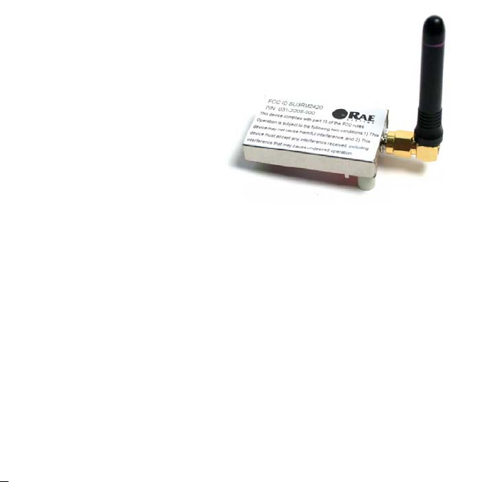
FCC Approved RM2420 RF Communication Module Data Sheet
RAE Systems has partnered with Ember to manufacture and promote
module-level products. RAE Systems manufactures the EM2420 RF
Communications Module as the RM2420 RF Communications Module.
The RM2420 module offers a complete microcontroller/transceiver solution
Containing all hardware features necessary for development of a low-
data-rate, low-power wireless application. The primary components
include a 2.4GHz, IEEE 802.15.4 compliant Zigbee-ready transceiver
(RM2420), an 8-bit microcontroller (ATmega128L or ATmega64L), a 40-pin
interface connector, a reverse-polar SAM antenna connector, three low profile
crystals (32.768KHz, 16MHz) and power management circuitry.
The RM2420 Module is available to companies who have purchased the Ember EM2420 Developer’s Kit and it
complies with part 15 of the FCC rules.
Specifications
Frequency Band 16 channels of operation in the 2.4GHz world wide ISM band. 5MHz
channel spacing.
High Performance RX sensitivity of better than -90 dBm at 1% packet error rate for a 20
byte payload.
Efficient Built-in CRC and AES-128 encryption. Buffered full packet transmit and
receive. High performance SPI data and control interface operates up to
10MHz.
Power +3.3V + .3V from carrier board, 3.0V to 3.6V from battery pack
Microcontroller ATmega128L (U2) or Atmega64L (U2).
Radio RM2420 (U5)
Rx sensitivity; -94dBm (1% PER, 20-byte packet) Type
Tx power: 0dBm max
Interfaces 40-pin surface-mount RM2420 RCM header (J1)
2-pin surface-mount right-angle battery connector (J2)
Flexible Designed for a broad spectrum of applications including IEEE 802.15.4
and Zigbee compliant devices.
Range Line of sight range of 75 meters. Available option of a +10dBm output
amplifier for longer range transmission.
RF 250kbps OQPSK Direct Sequence Spread Spectrum radio in
accordance with the IEEE 802.15.4 specification. 0dBm output power.
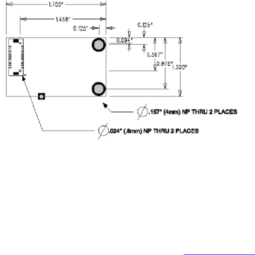
Dimensions 1 x 1.75 inches
Antenna Interface 50-Ohm reverse polar SMA
Operating Temperature Range -40ºC to +85ºC
External Power Pin Used to power external sensors (J1.7)
20mA max
Indicators Two LEDs, one red, one yellow (DS1, DS2)
Specifications (continued)
Operating Voltage 1.8 V (1.6 V to 2.0 V) Internal Regulator Disabled
3.3 V (2.0V to 3.6 V) Internal Regulator Enabled
Current Consumption 0.5 µA Sleep
20.7 mA TX @ 0 dBm
19.7 mA RX / Idle
Frequency Range 2405 to 2480 MHz
Output Power -32 to +0 dBm
Data Rate 250 kbps
FCC ID SU3RM2420 - Complies with Part 15 of the FCC rules. Operation is
subject to the following two conditions: 1) This device may not cause
harmful interference, and 2) This device must accept any interference
received, including interference that may cause undesired operation
*On going projects to enhance our products means that these specifications are subject to changes
Interface Decal Dimensions
Components
Microcontroller (U2)
The 8-bit flash-based ATmega 128L/ATmega64L microcontroller contains software for the configuration and
control of the RM2420, AMC and network functions, and the user-defined application software. The
microcontroller utilizes a 32.768KHz crystal for MAC timing and power management, as well as external crystal
operating at 8Hz. A variety of peripherals are routed to headers on the Developer Kit carrier board for
application development. For detail information on the microcontroller, see www.atmel.com.
When configuring the Ember Studio Debug Reader, enter the following baud rate into the Debug Preference
Window: 100,000. This rate is set by the microcontroller operating frequency.
Radio (U5)
The radio is an RM2420, a true single-chip 2.4GHz IEEE 802.15.4 – compliant and Zigbee-ready radio
frequency transceiver designed for low-power and low-voltage wireless applications. It includes a digital direct
sequence spread-spectrum (DSSS) baseband modem with an effective data rate of 250kbps.
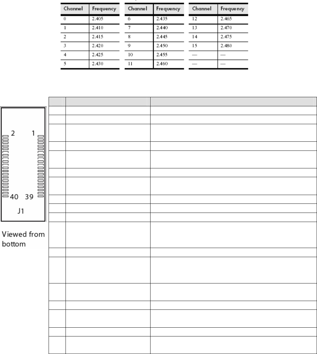
Channel Frequencies
These channels are equivalent to IEEE 802.15.4 channels 11 to 26.
RM2420 Channel Frequencies (GHz)
Pin Layout
Pin ATmega 128/64 Pin Name Description
1 GND Digital GND
2 GND Digital GND
3 PD3 (TXD1/INT3) EmberNet stack defaults to Alternate Function TX UART
(TXD1)
4 nRESET External reset, active low
5 PD2 (RXD1/INT2) EmberNet stack defaults to Alternate Function RX UART
(Rxd1)
6 PG1 (nRD) General purpose I/O
7 +3.3V out External power pin used to run custom external sensors
and/or devices; 20mA max
8 +3.3V in Input power from carrier boards
9 GND Digital GND
10 GND Digital GND
11 PD1 (SDA/INT1) General purpose I/O; EmberNet defaults signal as an
output connected to EM2 (button 1) on carrier board (with
J11 installed)
12 PG0 (nWR) General purpose I/O
13 PD0 (SDl/INT0) General purpose I/O; EmberNet defaults signal as an
output connected to EM1 (button 0) on carrier board (with
J10 installed)
14 PC2 Dedicated connection to red LED (D55 on carrier board)
for debugging purposes
15 PB7 (OC2/OC1C) General purpose I/O
16 PC3 Dedicated connection to yellow LED (DS4 on carrier
board) for debugging purposes
17 PB6 General purpose I/O
18 PC5 Dedicated connection to orange LED (DS2 on carrier
board) for debugging purposes
19 NC Dedicated for use with carrier board emulator/debug
module
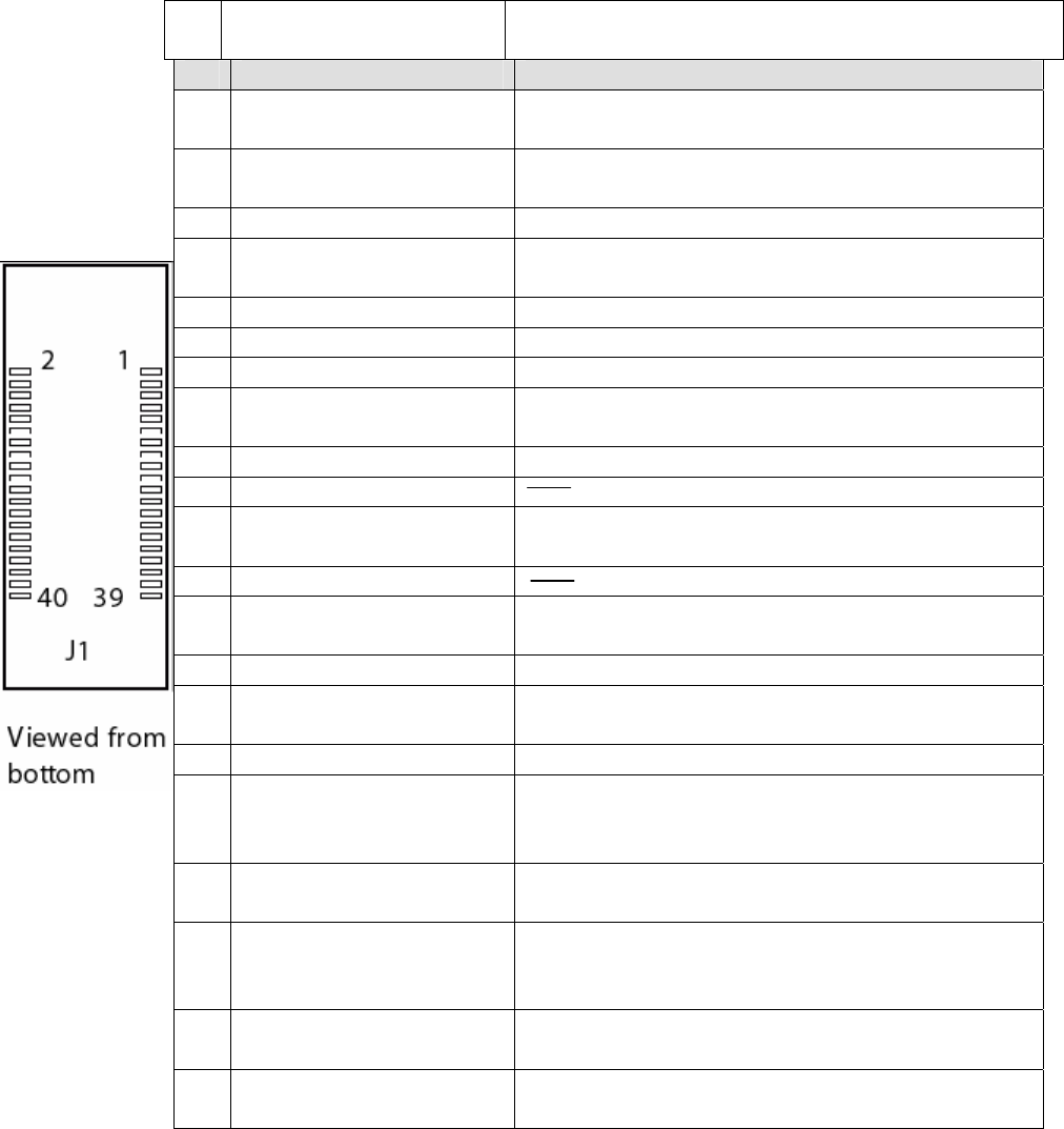
Pin ATmega 128/64 Pin Name Description
20 PC6 Dedicated connection to green LED (DS3 on carrier
board) for debugging purposes
21 PB3 Master In/Slave Out SPI (used to configure the
EM2420)
22 PG2 General purpose I/O
23 PB2 (MOSI) Master Out/Slave In SPI (used to configure the
RM2420)
24 AVCC Analog voltage reference pin
25 PB1 (SCK) SPI clock (used to configure the RM2420)
26 AGND Analog ground pin (same as digital GND)
27 PC1 Dedicated signal for Temperature Enable (active high)
for temperature sensor on carrier board
28 AREF ADC voltage reference pin
29 NC
30 PF1 (ADC1) EmberNet stack uses alternate function ACD1 to
monitor external battery pack voltage
31 NC
32 PF2 (ADC2) EmberNet stack uses alternate function ACD2 for
temperature calibration
33 PE3 (OC3A/AIN1) General purpose I/O
34 PF4 (ADC4/TCK) General purpose I/O; if JTAG is enabled, the
EmberNet stack uses alternate function TCK for JTAG
35 PE2 (XCK0/AIN0) General Purpose I/O
36 PF5 (ADC5/TMS) General purpose I/O; if JTAG is enabled, the
EmberNet stack uses alternate function TMS for
JTAG
37 PE1 (TXD0/PDO) EmberNet stack defaults to alternate function TX
UART (TXD0)
38 PF6 (ADC6/TDO) General purpose I/O; if JTAG is enabled, the
EmberNet stack uses alternate function TDO for
JTAG
39 PE0 (RXD0/PDI) EmberNet stack defaults to alternate function RX
UART (RXD0)
40 PF7 (ADC7/TDI) General purpose I/O; if JTAG is enabled, the
EmberNet stack uses alternate function TDI for JTAG
Instructions
All users of this device must state on the outside of the host “Contains FCC ID: SU3RM2420”.
Warning (Part 15.21)
Changes or modifications not expressly approved by the party responsible for compliance could void the user’s
authority to operate the equipment.
This device must be operated as supplied by RAE Systems. Any changes or modifications made the device
RM2420 can be jeopardize, but there is one exception. The radio’s antenna can be replaced as long as the
specification of the antenna matches the original (ant-2.4-cw-rcs-sma by Linx technologies).