RAE Systems RM900A-01 RAE Mesh module User Manual RM900A manual
RAE Systems, Inc RAE Mesh module RM900A manual
RM900A_manual

900MHz Wireless Modem
RM900A
1.1 Summary
RM900A is a
high-tx power,
high-sensitivity
868/915MHz IEEE
802.15.4 module,
which offers a
complete
microcontroller/tran
sceiver solution
containing all
hardware features
necessary for
development of
wireless application.
1.2 Key Features
Document Information
Info Content
Author(s) Kong Juan
Revision 1.0
Document Status First release
Date Dec 11, 2015
Distribution Internal Use Only
Approvals
Name Date Signature
Zhao Pengjun
James Liu
• Frequency Band 868-868.6MHz, 910-924MHz
11 channels
• Power +3.3V ±0.3V from carrier board, 3.0V to 3.6V from
battery pack
• Interfaces 40-pin surface-mount 2x20 1.27mm pitch
• RF 40kbps BPSK DSSS @915MHz
20kbps BPSK DSSS @868MHz
• Dimensions 46.5 mm x 26 mm x 10 mm
• Antenna Interface 50-Ohm MMCX female or UFL connector
• Operating Temperature Range
-40ºC to +85ºC
• Indicators Two LEDs, one red, one yellow (DS1, DS2)
• Current Consumption 600µA Sleep
170mA TX @ Medium Level 25℃
35mA RX/Ideal
• RF receive sensitivity -100dBm at at 1% packet error rate for a 20 byte
payload.
• Output Power EIRP Up to 20dBm
1.3 Abbreviations and Acronyms
ADC Analog-to -Digital Converter
API Application Programming Interface
BPSK Binary Phase-Shift Keying modulation scheme
DC Direct Current
DTR Data Terminal Ready
EEPROM Electrically Erasable Programmable Read-Only Memory
ESD Electrostatic Discharge
GPIO General Purpose Input/Output
HVAC Heating, Ventilating and Air Conditioning
HW Hardware
I2C Inter-Integrated Circuit
IEEE Institute of Electrical and Electrionics Engineers
IRQ Interrupt Request
ISM Industrial, Scientific and Medical radio band
JTAG
Digital interface for debugging of embedded device, also known as IEEE 1149.1 standard
interface
MAC Medium Access Control layer
MCU
Microcontroller Unit. In this document it also means the processor, which is the core of
ZigBit
module
O-QPSK Offset Quadrature Phase-Shift Keying modulation scheme
OEM Original Equipment Manufacturer
OTA Over-The-Air upgrade
PCB Printed Circuit Board
PER Package Error Ratio
RAM Random Access Memory
RF Radio Frequency
RTS/CTS Request to Send/ Clear to Send
RX Receiver
SMA Surface Mount Assembly
SPI Serial Peripheral Interface
SW Software
TTM Time To Market
TX Transmitter
UART Universal Asynchronous Receiver/Transmitter
USART Universal Synchronous/Asynchronous Receiver/Transmitter
USB Universal Serial Bus
ZDK ZigBit Development Kit
ZigBee,
ZigBee PRO
Wireless networking standards targeted at low-power applications
802.15.4 The IEEE 802.15.4-2006 standard applicable to low-rate wireless Personal Area
Network
2.1 Overview
RM900A works at 868MHz/910-924MHz, 11 channels, channel spacing 2MHz. You
can change its TX power, working channel through com tool.
RM900A is a high Tx-power, high sensitivity IEEE 802.15.4/ZigBee module. Based on
a combination of Atmel’s latest MCU wireless hardware platform, power amplifier and low
noise amplifier, the RM900A offers superior radio performance.
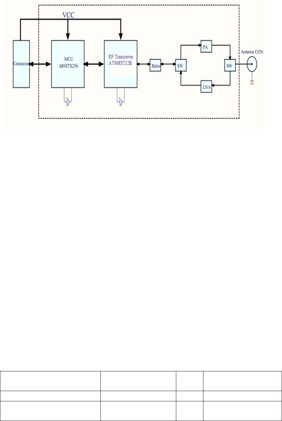
The module contains Atmel’s AT91SAM7X256 Microcontroller, AT86RF212B RF
transceiver, balun, two RF switches, power amplifier and low noise amplifier.
The balun transforms the differential radio transceiver RF signals (RFP/RFN) to a
single ended RF signal. The RF switches separate between receive and transmit path.
These switches are controlled by the RX/TX indicator.
During receive the RF signal, switch will send it to the low noise amplifier. The signal
will be amplified by the low noise amplifier and fed to the radio transceiver AT86RF212B
using the second RX/TX switch and balun.
During transmit, the AT86RF212B’s TX signal is amplified using a power amplifier, and
then fed to the antenna via the RF switch.
3.1 Modem Characteristics
3.1.1 Electric Characteristics
Test conditions (unless otherwise stated), Vcc=3V, Tamb=25°C
Parameters Range Unit Condition
Supply Voltage (Vcc) 3 to 3.6 V
Current Consumption: RX
mode
40 mA

3.1.2 RF Characteristics
3.2 Pin Configuration
Current Consumption: TX
mode
170 mA TX: Mid
Current Consumption: Sleep
mode
600 uA
Parameters Range Unit Condition
Frequency Band 868-868.6/910-924 MHz
Number of Channel 1/10
Channel Spacing 2 MHz
Transmitter Output Power +20(max) dBm
Receiver Sensitivity -105 dBm
On-Air Data Rate 40(@915MHz)
20(@868MHz) kbps BPSK modulation
DSSS
Tx output/Rx input Nominal
Impedence
50 Ω
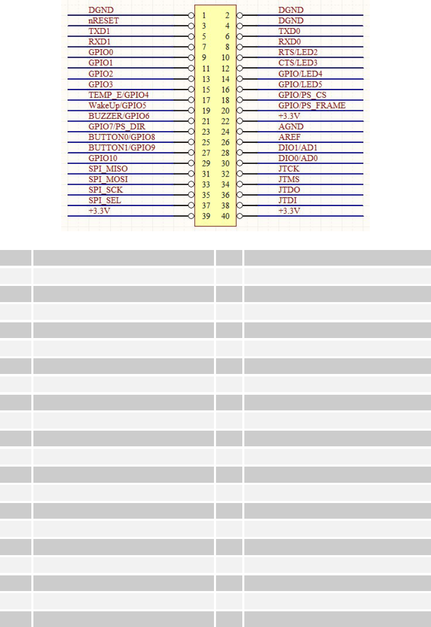
Pin Description Pin
Description
1 DGND 2 DGND
3 nRESET 4 DGND
5 TXD1 6 TXD0
7 RXD1 8 RXD0
9 GPIO0 10 RTS/LED2
11 GPIO1 12 CTS/LED3
13 GPIO2 14 GPIO/LED4
15 GPIO3 16 GPIO/LED5
17 TEMP_E/GPIO4 18 GPIO/PS_CS
19 WakeUp/GPIO5 20 GPIO/PS_FRAME
21 BUZZER/GPIO6 22 +3.3V
23 GPIO7/PS_DIR 24 AGND
25 BUTTON0/GPIO8 26 AREF
27 BUTTON1/GPIO9 28 DIO1/AD1
29 GPIO10 30 DIO0/AD0
31 SPI_MISO 32 JTCK
33 SPI_MOSI 34 JTMS
35 SPI_SCK 36 JTDO
37 SPI_SEL 38 JTDI
39 +3.3V 40 +3.3V
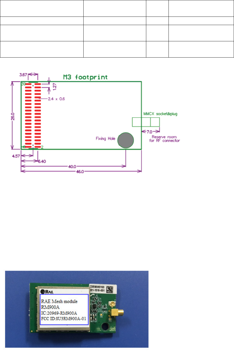
3.3 Physical Characteristics
3.4 Antenna Reference
• Suggest antenna:868MHz/910~924MHz antenna
• MMCX connector on board, need a RF cable to antenna, such as
MMCX to SMA RF cable.
• Reserved UFL connector on board.
3.5 Label
Parameters Range Unit Condition
Size 46×26×7 mm
Operation Temmperature
Range
-40 to +55 ℃
Operation Relative Humidity
Range
No more than 80%
Caution:
This device complies with Part 15 of the FCC Rules / Industry Canada licence-exempt
RSS standard(s). Operation is subject to the following two conditions: (1) this device
may not cause harmful interference, and (2) this device must accept any
interference received, including interference that may cause undesired operation.
Le présent appareil est conforme aux CNR d'Industrie Canada applicables aux
appareils radio exempts de licence. L'exploitation est autorisée aux deux conditions
suivantes : (1) l'appareil ne doit pas produire de brouillage, et (2) l'utilisateur de
l'appareil doit accepter tout brouillage radioélectrique subi, même si le brouillage est
susceptible d'en compromettre le fonctionnement.
Changes or modifications not expressly approved by the party responsible for
compliance could void the user's authority to operate the equipment.
This equipment has been tested and found to comply with the limits for a Class B
digital device, pursuant to part 15 of the FCC Rules. These limits are designed to
provide reasonable protection against harmful interference in a residential
installation. This equipment generates uses and can radiate radio frequency energy
and, if not installed and used in accordance with the instructions, may cause harmful
interference to radio communications. However, there is no guarantee that
interference will not occur in a particular installation. If this equipment does cause
harmful interference to radio or television reception, which can be determined by
turning the equipment off and on, the user is encouraged to try to correct the
interference by one or more of the following measures:
—Reorient or relocate the receiving antenna.
—Increase the separation between the equipment and receiver.
—Connect the equipment into an outlet on a circuit different from that to which the
receiver is connected.
—Consult the dealer or an experienced radio/TV technician for help.
Under Industry Canada regulations, this radio transmitter may only operate using an
antenna of a type and maximum (or lesser) gain approved for the transmitter by
Industry Canada. To reduce potential radio interference to other users, the antenna
type and its gain should be so chosen that the equivalent isotropically radiated
power
(e.i.r.p.) is not more than that necessary for successful communication.
Conformément à la réglementation d'Industrie Canada, le présent émetteur radio
peut
fonctionner avec une antenne d'un type et d'un gain maximal (ou inférieur) approuvé
pour l'émetteur par Industrie Canada. Dans le but de réduire les risques de
brouillage radioélectrique à l'intention des autres utilisateurs, il faut choisir le type
d'antenne et son gain de sorte que la puissance isotrope rayonnée équivalente
(p.i.r.e.) ne dépasse pas l'intensité nécessaire à l'établissement d'une communication
satisfaisante.
MPE Reminding
To satisfy FCC / IC RF exposure requirements, a separation distance of 20 cm or more
should be maintained between the antenna of this device and persons during device
operation.
To ensure compliance, operations at closer than this distance is not recommended.
Les antennes installées doivent être situées de facon à ce que la population ne puisse
y être exposée à une distance de moin de 20 cm. Installer les antennes de facon à ce
que le personnel ne puisse approcher à 20 cm ou moins de la position centrale de l’
antenne.
La FCC des éltats-unis stipule que cet appareil doit être en tout temps éloigné d’au
moins 20 cm des personnes pendant son functionnement.
Information for the OEM Integrators
This device is intended for OEM integrators only. Please see the full grant of
equipment document for restrictions.
Ce dispositif est destiné aux équipementiers et intégrateurs. S'il vous plaît voir la
pleine subvention du document de l'équipement pour les restrictions.
Label Information to the End User by the OEM or Integrators
If the FCC ID of this module is not visible when it is installed inside another device,
then the outside of the device into which the module is installed must be label with
“Contains FCC ID: SU3RM900A-01 and Contains IC: 20969-RM900A”.
Si l'ID FCC de ce module est pas visible quand il est installé dans un autre appareil,
puis l'extérieur du dispositif dans lequel le module est installé doit être étiquette
avec"Contient FCC ID: SU3RM900A-01 et Contient IC: 20969-RM900A".