RAE Systems RMWIFI RAE WIFI Module User Manual Rev 1
RAE Systems, Inc RAE WIFI Module Rev 1
User Manual_Rev 1

RAE Systems by Honeywell
Honeywell Confidential and Proprietary Revision –1.0 Page 1 of 29
Copyright © 2015 Honeywell Analytics, All rights reserved.
User Guide for RMWIFI
Document Information
Info
Content
Author(s)
Wu Wei
Revision
1.0
Document Status
Draft
Date
Oct. 20 2014
Distribution
Internal Use Only
Approvals
Name
Date
Signature
James Liu
Zhao Pengjun

RAE Systems by Honeywell
Honeywell Confidential and Proprietary Revision –1.0 Page 2 of 29
Copyright © 2015 Honeywell Analytics, All rights reserved.
Release Histroy
Rev.
Date
Author
Descripition
1.0
Oct. 20 2014
Wu Wei
Original

RAE Systems by Honeywell
Honeywell Confidential and Proprietary Revision –1.0 Page 3 of 29
Copyright © 2015 Honeywell Analytics, All rights reserved.
Contents
1. Section1: ............................................................................................................................................... 4
1.1 Summary: ................................................................................................................................ 4
1.2 Key Features:.......................................................................................................................... 4
2. Section2: ............................................................................................................................................... 4
2.1 Overview: ................................................................................................................................ 4
2.2 Pin Definition: ........................................................................................................................ 5
3. Section3: ............................................................................................................................................... 6
3.1 Voltage: .................................................................................................................................... 6
3.2 Current Consumption: .......................................................................................................... 6
3.3 I/O DC Specification: ............................................................................................................. 7
3.4 Mechanical Drawing: ............................................................................................................ 7
4. How to program RMWIFI: ..................................................................................................................... 8
4.1 Hardware interface setup:................................................................................................... 8
4.2 Program software interface introduction: ....................................................................... 9
4.3 Running application firmware ........................................................................................... 9
5. Initialization: ....................................................................................................................................... 10
5.1 Get module type:.................................................................................................................. 10
5.2 Get MAC address: ................................................................................................................. 11
6. Scan and associate with AP: ............................................................................................................... 12
6.1 Scan network: ...................................................................................................................... 12
6.2 Set password: ....................................................................................................................... 15
6.3 Associate with AP: ............................................................................................................... 16
7. How to communicate using TCP: ........................................................................................................ 17
7.1 Connect to TCP server: ....................................................................................................... 17
7.2 Receive data packet from server: .................................................................................... 20
7.3 Send data packet to server: ............................................................................................... 21
8. How to communication using UDP: .................................................................................................... 23
8.1 Receive data packet from UDP server: ............................................................................ 23
8.2 Send data packet to remote using UDP: .......................................................................... 25

RAE Systems by Honeywell
Honeywell Confidential and Proprietary Revision –1.0 Page 4 of 29
Copyright © 2015 Honeywell Analytics, All rights reserved.
1. Section1:
1.1 Summary:
RMWIFI-M3 based on RMWIFI-M5 module provides a quick, easy and cost
effective way to add Wi-Fi capabilities for RAE Systems products, such as
AreaRAE2, MutlRAE2, and RAE-Hub etc.
The module combined 802.11 MAC, security, PHY functions, FLASH SRAM, and
external antenna connectors, provides a Wi-Fi radio for end customers. It also
integrates TCP/IP stack and other related network stacks such as DHCP client,
DHCP server and web server etc. It can be used to connect to Ethernet
conveniently and transfer data to network server like ProRAE Guardian directly.
1.2 Key Features:
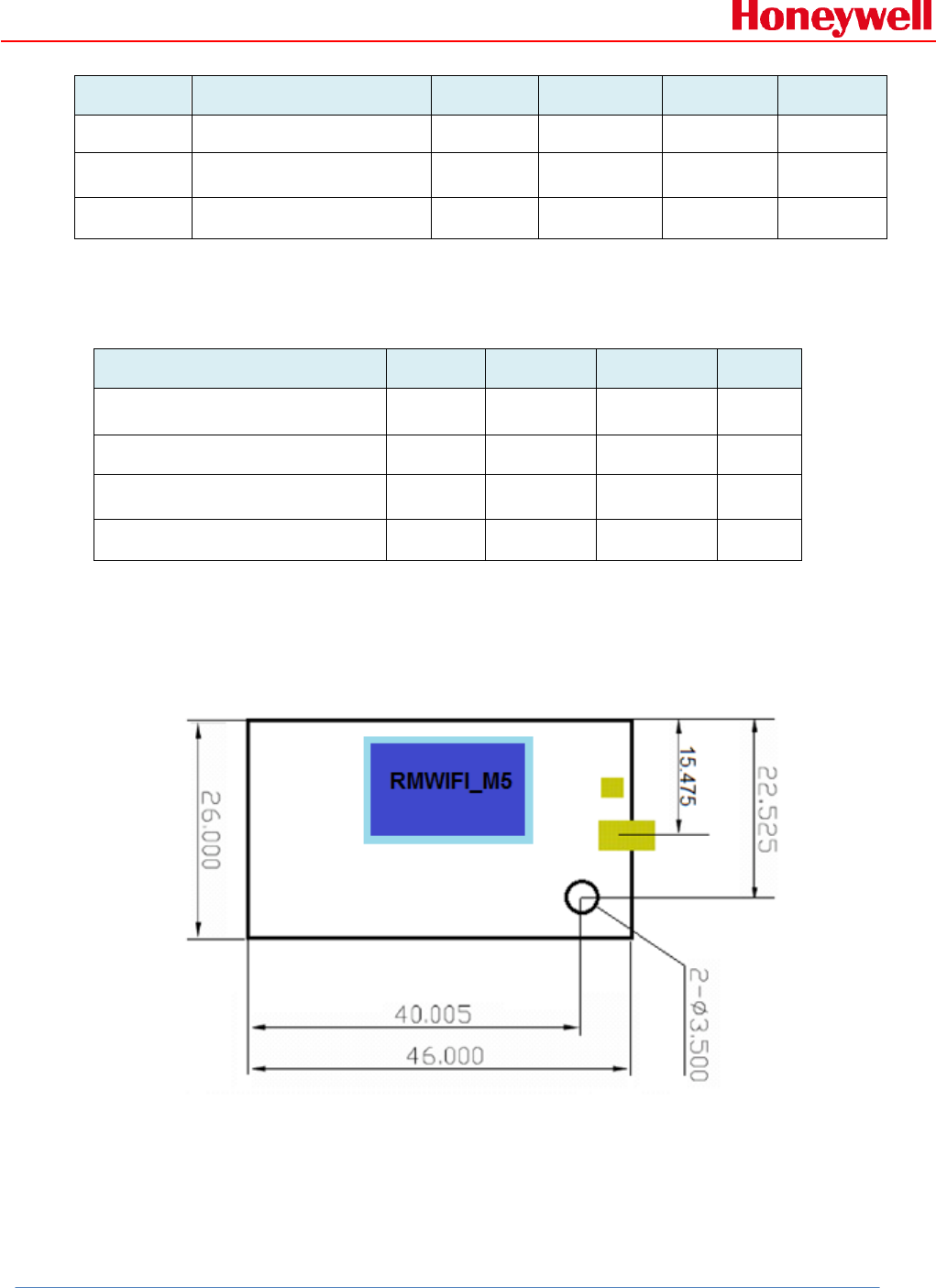
• 46 * 26 mm (Length * Width) with M3 40-PINs interface
• RCS protocol API for application interface
• DSSS modulation for 1and 2Mbps, CCK modulation for 5.5 and 11Mbps
• Compatible with IEEE 802.11 b
• UART interface, SPI interface, I2C interface, one ADC channel, several GPIOs
• Low power consumption
• RoHS compliant, certified lead- and halogen-free
2. Section2:
2.1 Overview:
RMWIFI-M3 operates in the unlicensed 2.4 radio bands IEEE 802.11b, which
supports Direct Sequence Spread Spectrum (DSSS) 1 Mb/s and 2 Mb/s data
rates, and Complementary Code Keyed (CCK) 5.5 Mb/s and 11 Mb/s data rates.
RMWIFI-M3 is based on RMWIFI-M5 module, which contains GS1011 WIFI
RAE Systems by Honeywell
Honeywell Confidential and Proprietary Revision –1.0 Page 5 of 29
Copyright © 2015 Honeywell Analytics, All rights reserved.
system-on-chip. The GS1011 have fully integrated RF Transceiver, low power
PA and application processor. Both TX and RX chain in the module incorporate
internal power control loops.
RMWIFI-M3 carries onboard single supply monitor for 1.8V voltage supply with
optional module controlled external regulator enable control pin (DC_DC_CNTL).
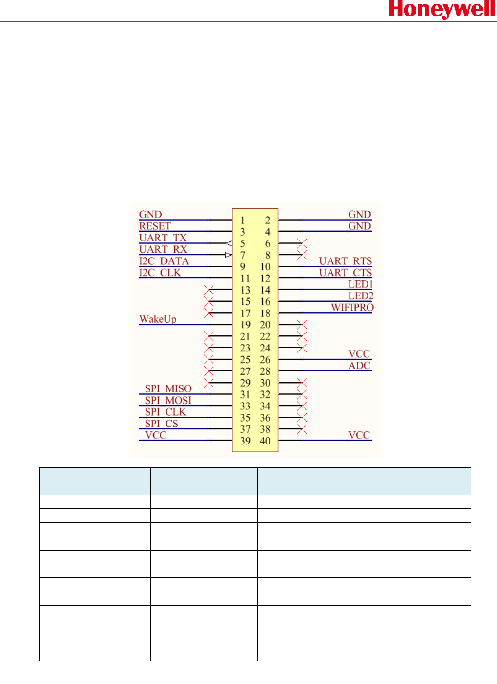
2.2 Pin Definition:
Connector
Pin
Pin Name
Description
I/O
1
GND
Ground
3
RESET
Active-low system reset
I/O
5
UART_TX
UART transmit output
O
7
UART_RX
UART transmit input
I
9
I2C_DATA
PU data signal for an external
I2C device
I/O
11
I2C_CLK
PU clk signal for an external
I2C device
I/O
13, 15, 17
NA
19
WakeUp
WakeUp the Module
I
21, 23, 25, 27, 29
NA
31
SPI_MISO
Slave SPI master in slave out
I/O
RAE Systems by Honeywell
Honeywell Confidential and Proprietary Revision –1.0 Page 6 of 29
Copyright © 2015 Honeywell Analytics, All rights reserved.
line
33
SPI_MOSI
Slave SPI master out slave in
line
I/O
35
SPI_CLK
Slave SPI clock line
I
37
SPI_CS
Slave SPI chip select line
I
39
VCC
Digital voltage supply
2, 4
GND
Ground
6, 8
NA
10
UART_RTS
RTS input (Request To Send)
for UART hardware flow
control
I
12
UART_CTS
CTS output (Clear To Send)
for UART hardware flow
control
O
14
LED1
LED indicate control PIN
O
16
LED2
LED indicate control PIN
O
18
WIFIPRO(1)
Enable/Disable into boot load
I
20, 22, 24
NA
26
VCC
Digital voltage supply
28
ADC
ADC input
30, 32, 34, 36, 38
NA
40
VCC
Digital voltage supply
Note (1): If WIFIPRO is high during boot, the WLAN will wait for Flash download via SPI or UART.
3. Section3:
3.1 Voltage:
Power supply for the RMWIFI-M3 module will be provided by the host power pins.
Symbol
Min
Typ
Max
Unit
VCC
3.0
3.3
3.6
V
3.2 Current Consumption:
Condition: 25deg.C. The default voltage is 3.3V.
RAE Systems by Honeywell
Honeywell Confidential and Proprietary Revision –1.0 Page 7 of 29
Copyright © 2015 Honeywell Analytics, All rights reserved.
Item
Condition
Min
Nom
Max
Unit
Receive
RX
108
mA
Transmit
Tx power setting: P=0
Single carrier
145
mA
Sleep
200
uA
3.3 I/O DC Specification:
Parameter
Symbol
Min
Max
Unit
Input Low Voltage
VIL
0.25*VCC
V
Input High Voltage
VIH
0.8*VCC
V
Output Low Voltage
VOL
0.4
V
Output High Voltage
VOH
0.8*VCC
V
3.4 Mechanical Drawing:
Unit: mm
RAE Systems by Honeywell
Honeywell Confidential and Proprietary Revision –1.0 Page 8 of 29
Copyright © 2015 Honeywell Analytics, All rights reserved.
4. How to program RMWIFI:
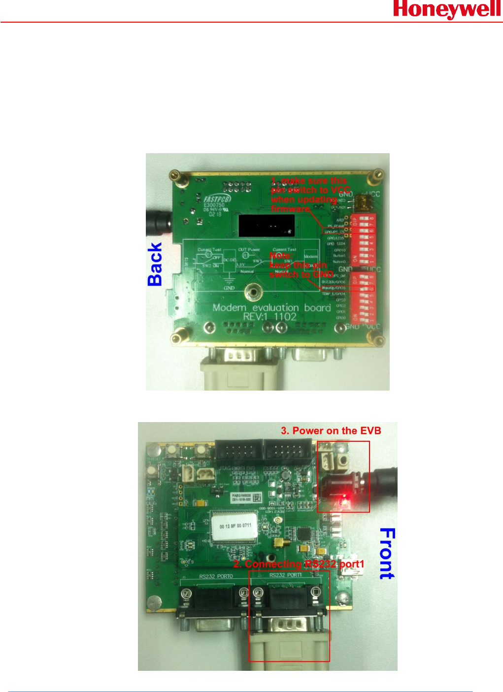
4.1 Hardware interface setup:
Configure the back side of the EVB as following picture:
Configure the front side of EVB as following picture:
RAE Systems by Honeywell
Honeywell Confidential and Proprietary Revision –1.0 Page 9 of 29
Copyright © 2015 Honeywell Analytics, All rights reserved.
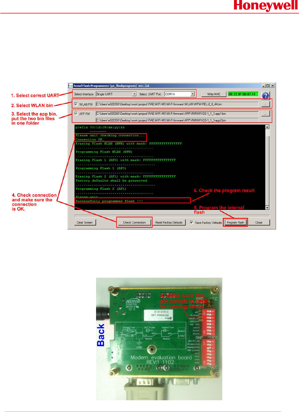
4.2 Program software interface introduction:
Programming RMWIFI modem needs three *.bin files which
including WLAN bin, APP bin1 and APP bin2, please see
following picture for detail:
4.3 Running application firmware
After upgrading RMWIFI modem firmware successfully,
configure the back side of the EVB as following picture:
RAE Systems by Honeywell
Honeywell Confidential and Proprietary Revision –1.0 Page 10 of 29
Copyright © 2015 Honeywell Analytics, All rights reserved.
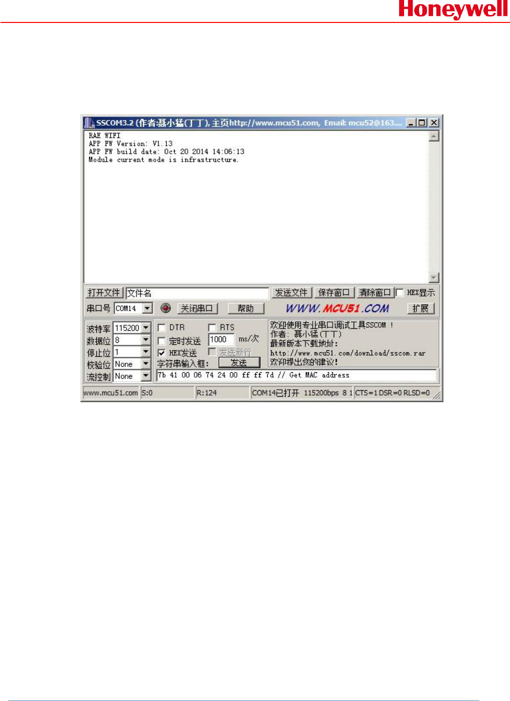
Then power-off and power on the EVB, RMWIFI modem application
firmware will run and output information as following picture via
EVB’s RS232 interface:
5. Initialization:
5.1 Get module type:
Host command:
7B 41 00 06 74 2E 00 FF FF 7D
RMWIFI response:
7B 41 00 07 75 2E 00 00 3F F3 7D
Example communication sequence:

RAE Systems by Honeywell
Honeywell Confidential and Proprietary Revision –1.0 Page 11 of 29
Copyright © 2015 Honeywell Analytics, All rights reserved.
Note:
In order to make it easy when using COMM tools to communicate
with RMWIFI, the CRC field of host command is replaced by FF FF.
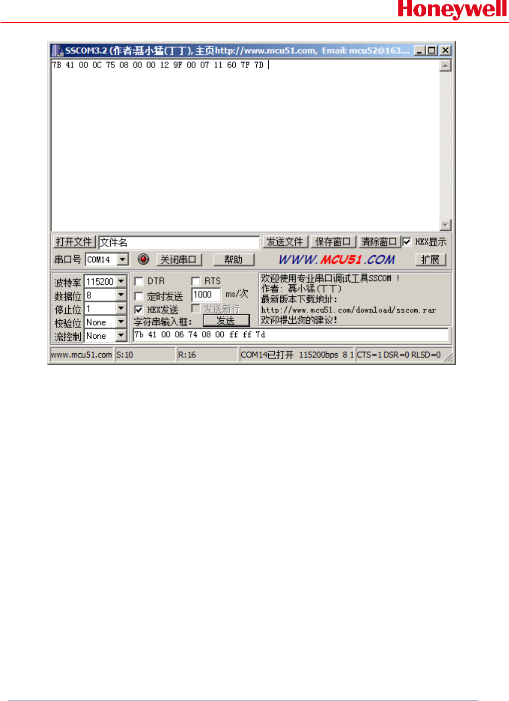
5.2 Get MAC address:
Host command:
7B 41 00 06 74 08 00 FF FF 7D
RMWIFI response:
7B 41 00 0C 75 08 00 00 12 9F 00 07 11 60 7F 7D
Example communication sequence:
RAE Systems by Honeywell
Honeywell Confidential and Proprietary Revision –1.0 Page 12 of 29
Copyright © 2015 Honeywell Analytics, All rights reserved.
6. Scan and associate with AP:
6.1 Scan network:
1. Send scan command
Host command:
7B 41 00 0A 74 0F 00 FF FF 00 00 FF FF 7D
RMWIFI response:
7B 41 00 0A 75 0F 00 00 00 04 4C 58 3F 7D
Example communication sequence:

RAE Systems by Honeywell
Honeywell Confidential and Proprietary Revision –1.0 Page 13 of 29
Copyright © 2015 Honeywell Analytics, All rights reserved.
2. Get scan status and AP number found:
Host command:
7B 41 00 06 74 10 00 FF FF 7D
RMWIFI response:
7B 41 00 08 75 10 00 00 01 29 0D 7D
Example communication sequence:

RAE Systems by Honeywell
Honeywell Confidential and Proprietary Revision –1.0 Page 14 of 29
Copyright © 2015 Honeywell Analytics, All rights reserved.
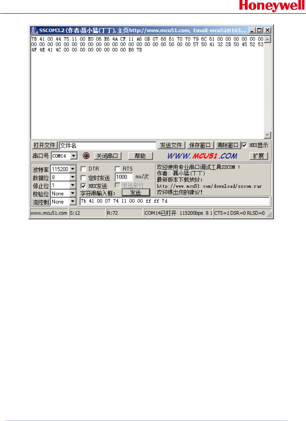
3. Get scanned AP information according to AP index:
Host command:
7B 41 00 07 74 11 00 00 FF FF 7D
RMWIFI response:
7B 41 00 44 75 11 00 E0 06 E6 4A CF 11 A6 0B 07 68 61 70 70 79 6C
61 00 00 00 00 00 00 00 00 00 00 00 00 00 00 00 00 00 00 00 00 00
00 00 00 00 00 57 50 41 32 2D 50 45 52 53 4F 4E 41 4C 00 00 00 00
00 00 00 00 B8 7D
Example communication sequence:
RAE Systems by Honeywell
Honeywell Confidential and Proprietary Revision –1.0 Page 15 of 29
Copyright © 2015 Honeywell Analytics, All rights reserved.
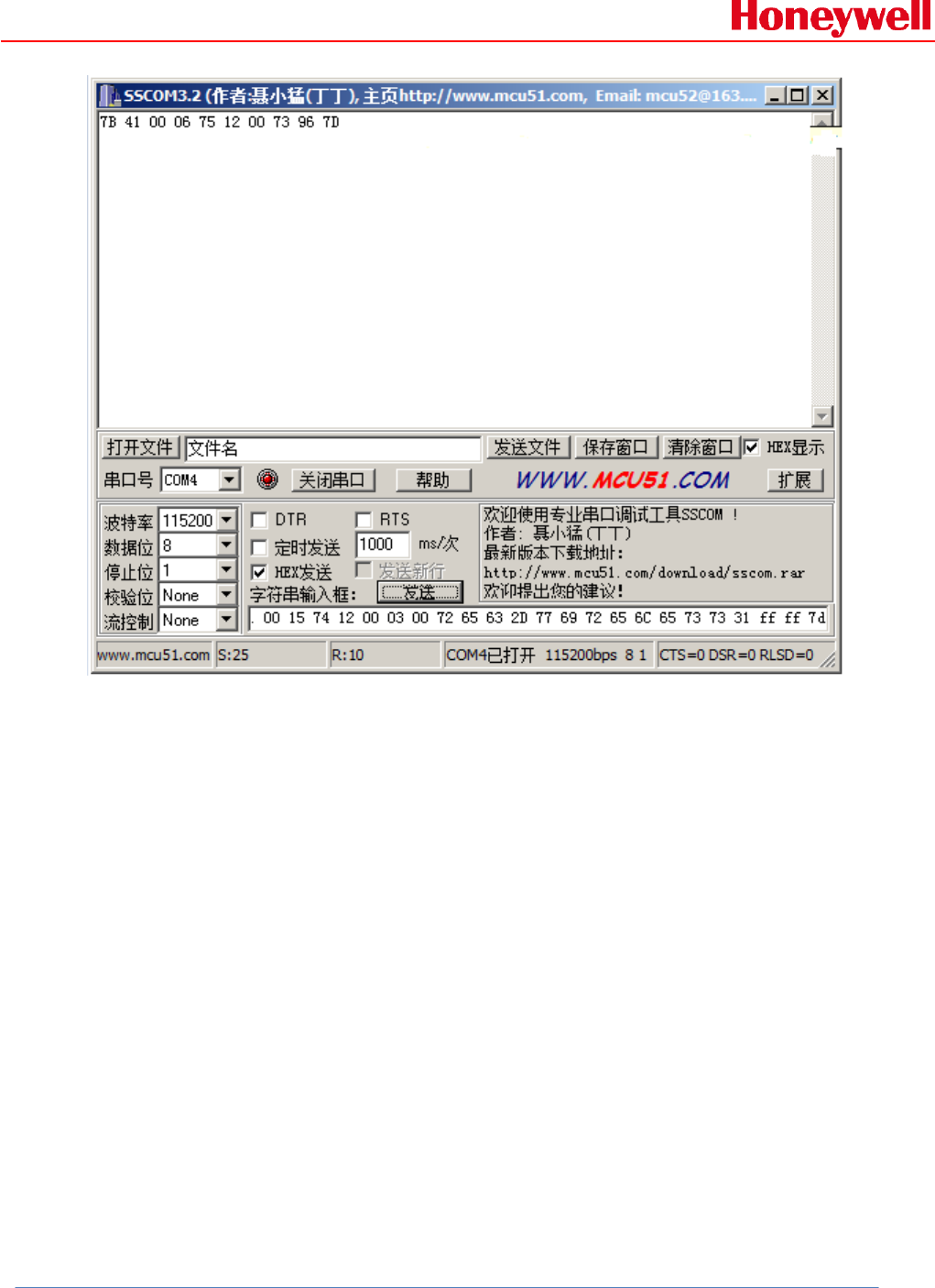
6.2 Set password:
Example:
If one AP uses WPA/WPA2, and the password is rec-wireless1
Host command:
7B 41 00 15 74 12 00 03 00 72 65 63 2D 77 69 72 65 6C 65 73 73 31
FF FF 7D
RMWIFI response:
7B 41 00 06 75 12 00 73 96 7D
Example communication sequence:
RAE Systems by Honeywell
Honeywell Confidential and Proprietary Revision –1.0 Page 16 of 29
Copyright © 2015 Honeywell Analytics, All rights reserved.
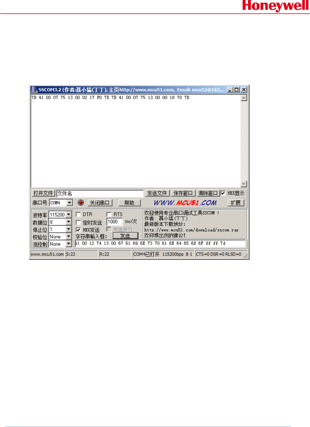
6.3 Associate with AP:
Example:
The AP SSID that the module wants to associate with is
gainspandemo.
Host command:
7B 41 00 12 74 13 00 67 61 69 6E 73 70 61 6E 64 65 6D 6F FF FF
7D
RMWIFI response:
7B 41 00 07 75 13 00 02 17 F0 7D
7B 41 00 07 75 13 00 00 18 70 7D
The Wi-Fi module will response two commands, first command
responses immediately after it receives the associate command
and indicates it’s doing. The second response command will delay
RAE Systems by Honeywell
Honeywell Confidential and Proprietary Revision –1.0 Page 17 of 29
Copyright © 2015 Honeywell Analytics, All rights reserved.
for seconds and indicates whether it associates with AP
successfully. Check the red byte of the response command, 0x00
indicates that it has associated with AP successfully.
Example communication sequence:
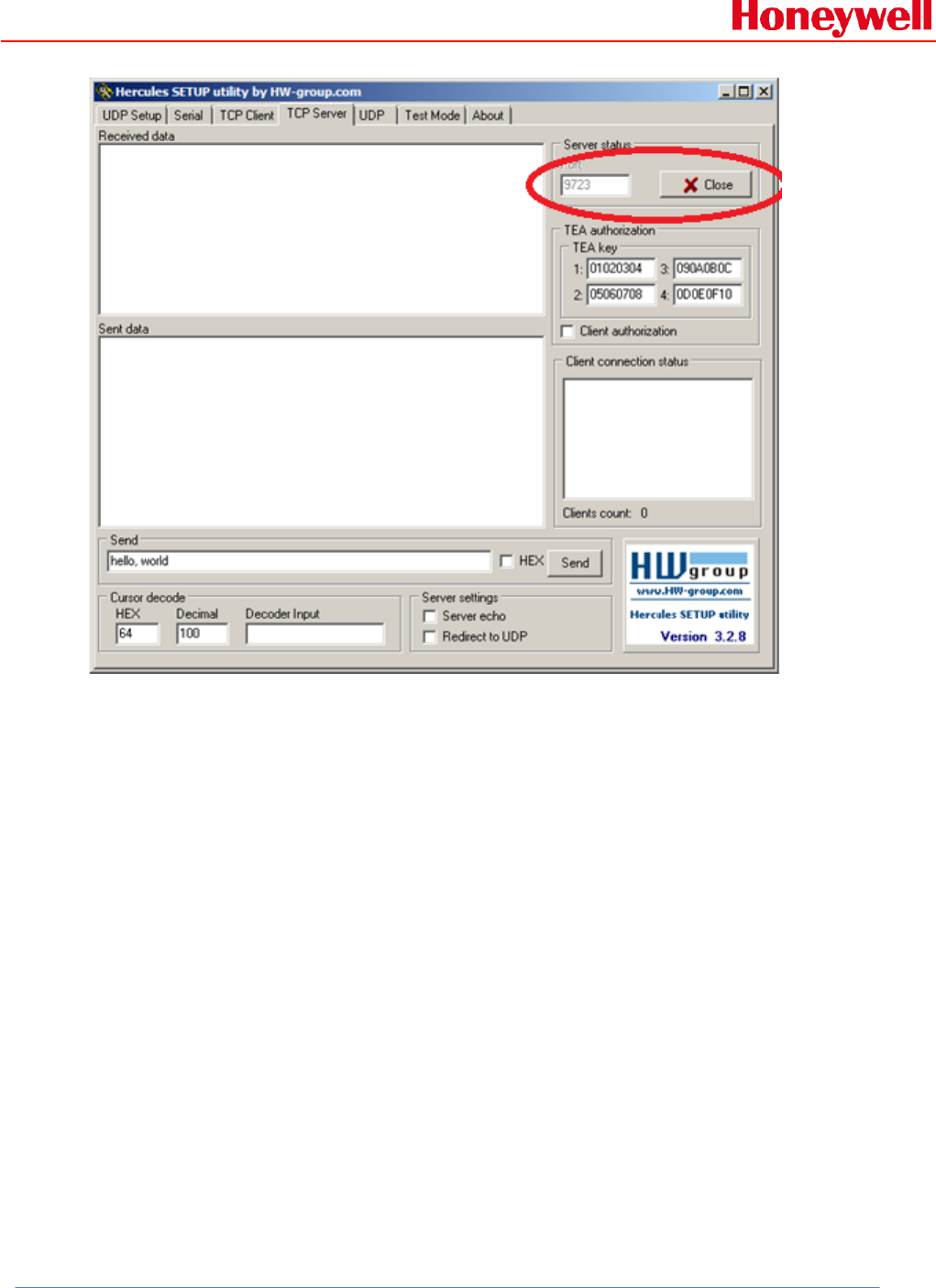
7. How to communicate using TCP:
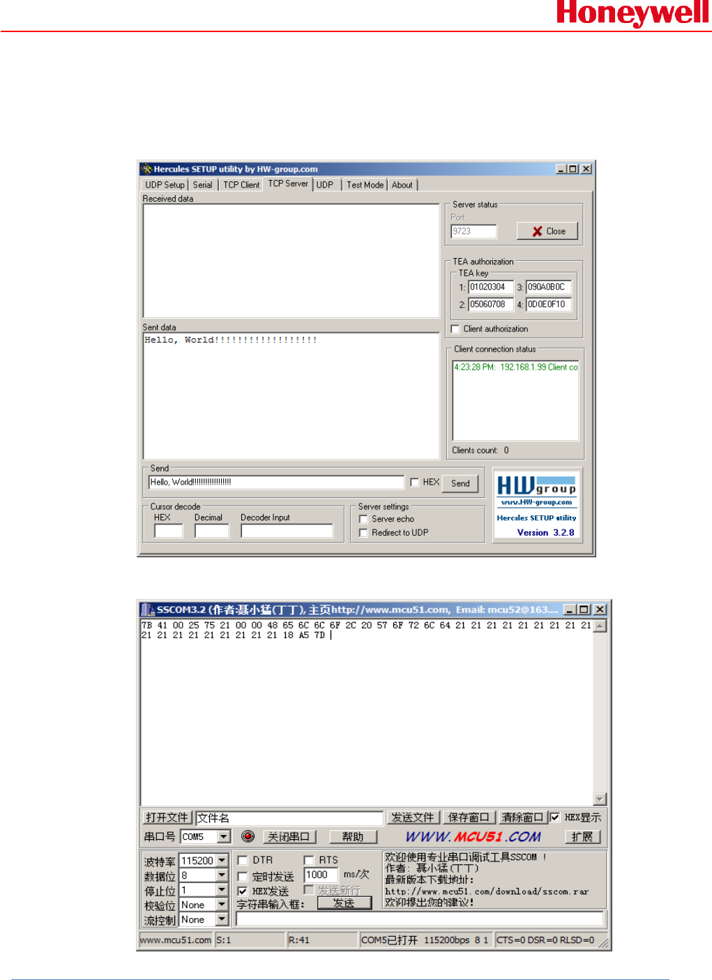
7.1 Connect to TCP server:
1. Use the socket test tool, create a TCP server as following picture,
the TCP listen port is 9723:
RAE Systems by Honeywell
Honeywell Confidential and Proprietary Revision –1.0 Page 18 of 29
Copyright © 2015 Honeywell Analytics, All rights reserved.
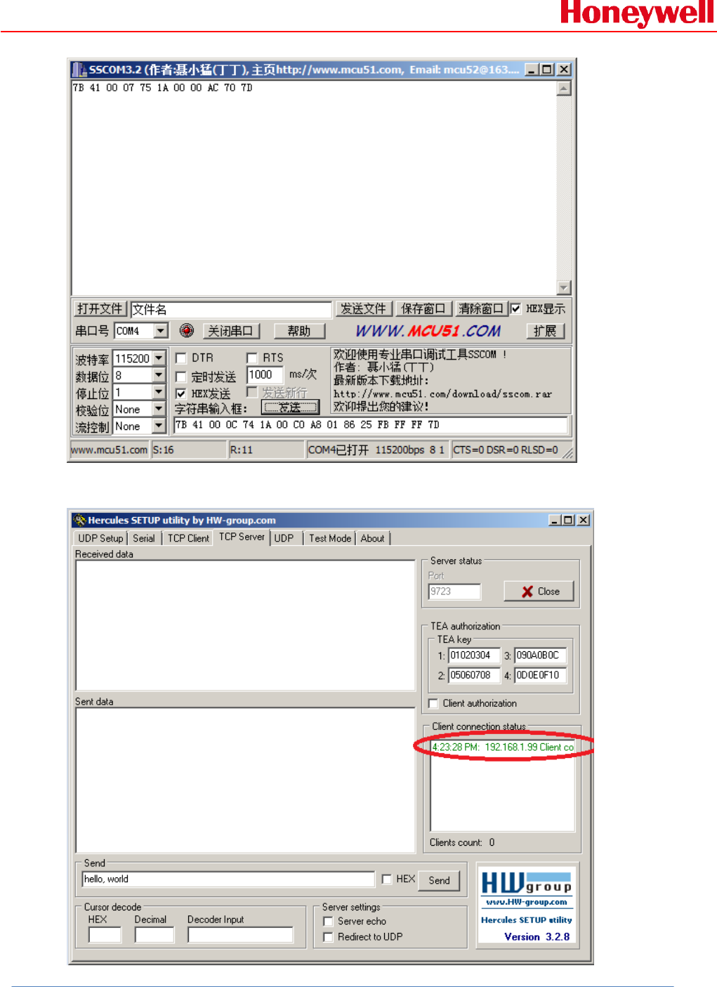
2. Connect to the TCP server:
Host command:
7B 41 00 0c 74 1A 00 c0 a8 01 86 25 fb ff ff 7d
RMWIFI response:
7B 41 00 07 75 1A 00 00 AC 70 7D
Example communication sequence:
RAE Systems by Honeywell
Honeywell Confidential and Proprietary Revision –1.0 Page 19 of 29
Copyright © 2015 Honeywell Analytics, All rights reserved.
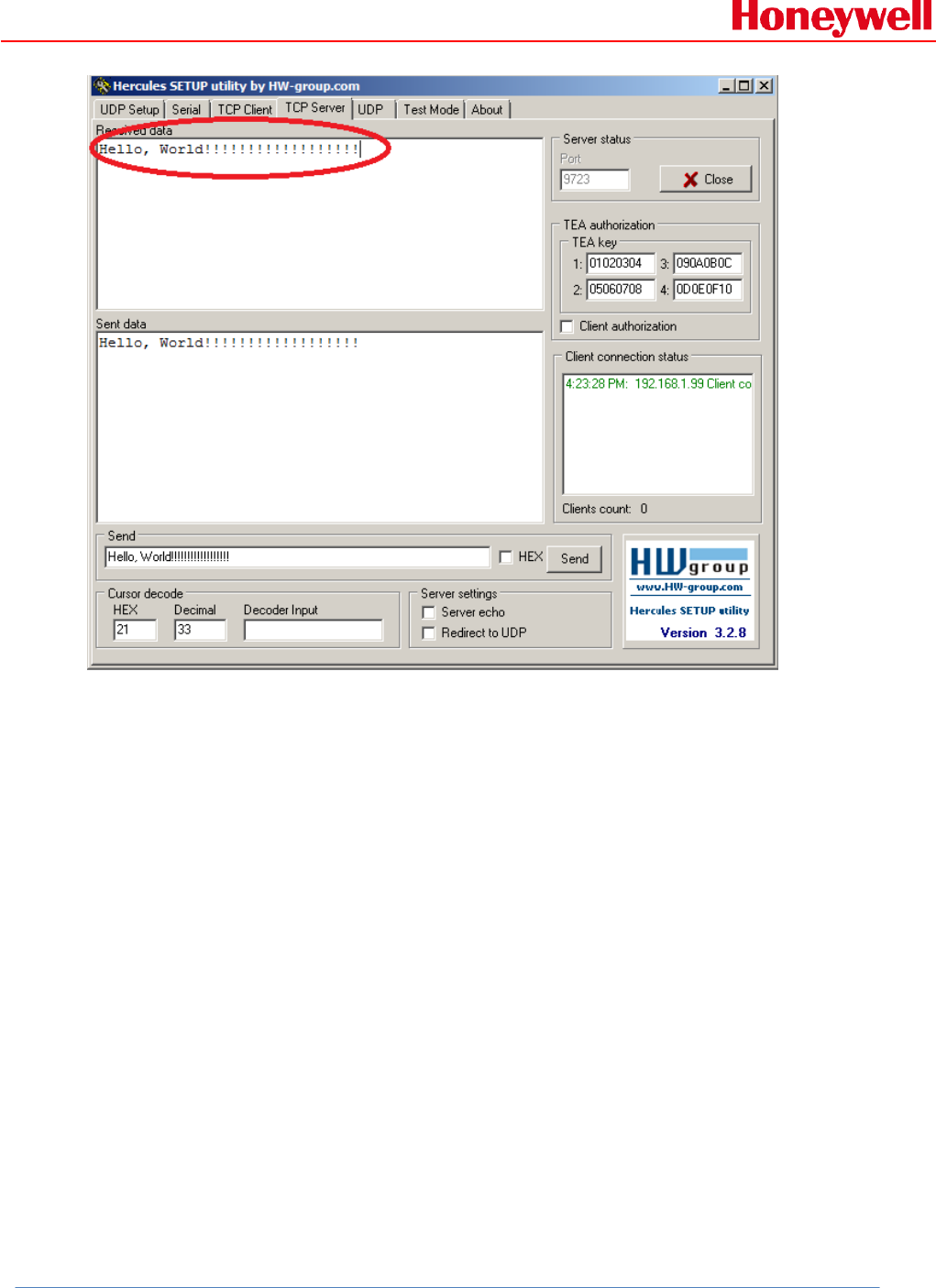
The socket test tools will inform that one client has connected to it:
RAE Systems by Honeywell
Honeywell Confidential and Proprietary Revision –1.0 Page 20 of 29
Copyright © 2015 Honeywell Analytics, All rights reserved.
7.2 Receive data packet from server:
From the socket test tools side, send data packet to RMWIFI as
following picture:
The RMWIFI will receive the data packet from TCP server:
RAE Systems by Honeywell
Honeywell Confidential and Proprietary Revision –1.0 Page 21 of 29
Copyright © 2015 Honeywell Analytics, All rights reserved.
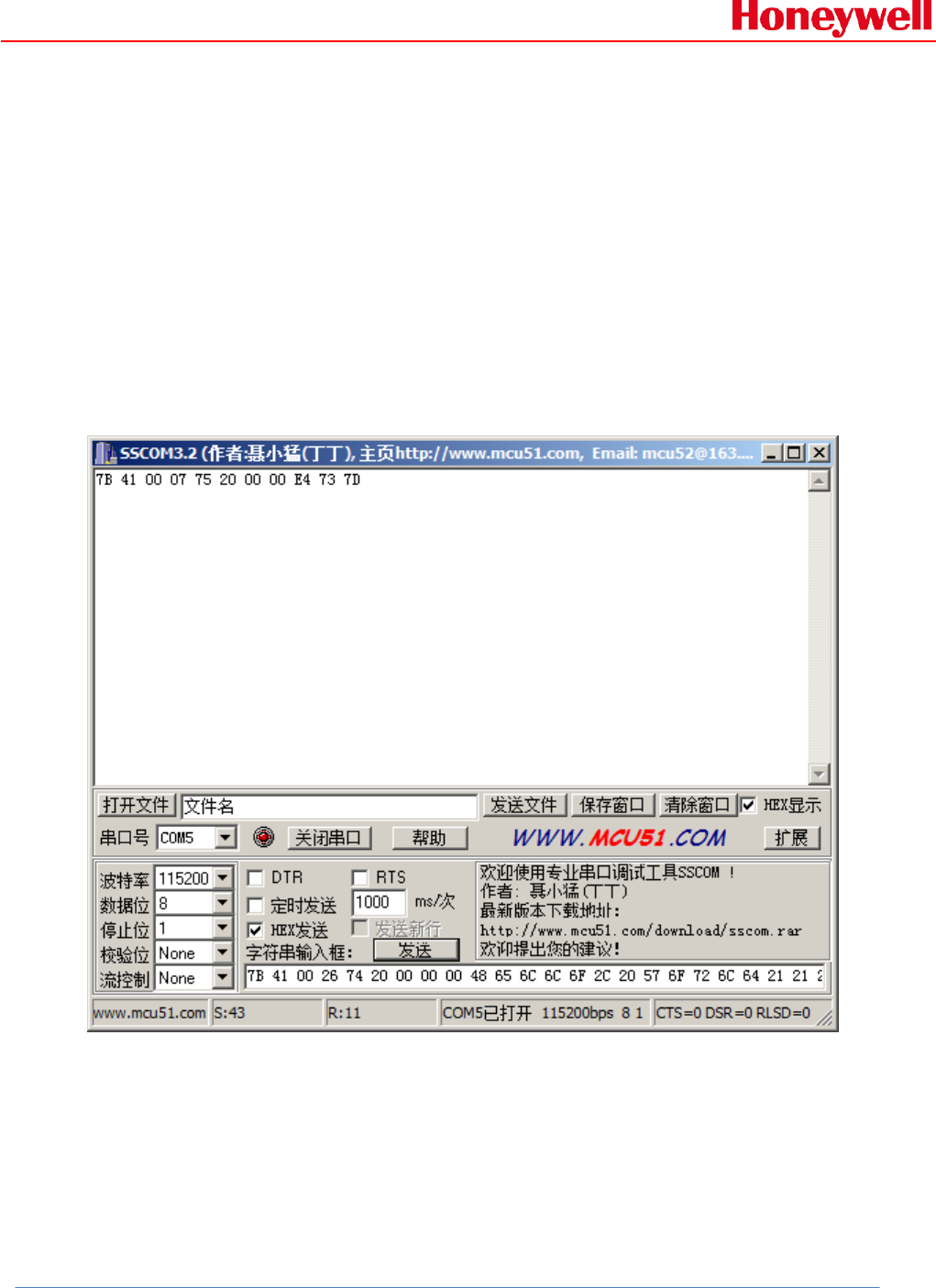
7.3 Send data packet to server:
Send the same data packet back to TCP server:
Host command:
7B 41 00 26 74 20 00 00 00 48 65 6C 6C 6F 2C 20 57 6F 72 6C 64 21
21 21 21 21 21 21 21 21 21 21 21 21 21 21 21 21 21 FF FF 7D
RMWIFI response:
7B 41 00 07 75 20 00 00 E4 73 7D
Example communication sequence:
The socket test tool side will receive the data packet as following
picture which is the same data packet as it sends out:
RAE Systems by Honeywell
Honeywell Confidential and Proprietary Revision –1.0 Page 22 of 29
Copyright © 2015 Honeywell Analytics, All rights reserved.
Note:
During doing the test, please make sure the host PC running the
socket test tools connects to the same AP as Wi-Fi module associate
with.
RAE Systems by Honeywell
Honeywell Confidential and Proprietary Revision –1.0 Page 23 of 29
Copyright © 2015 Honeywell Analytics, All rights reserved.
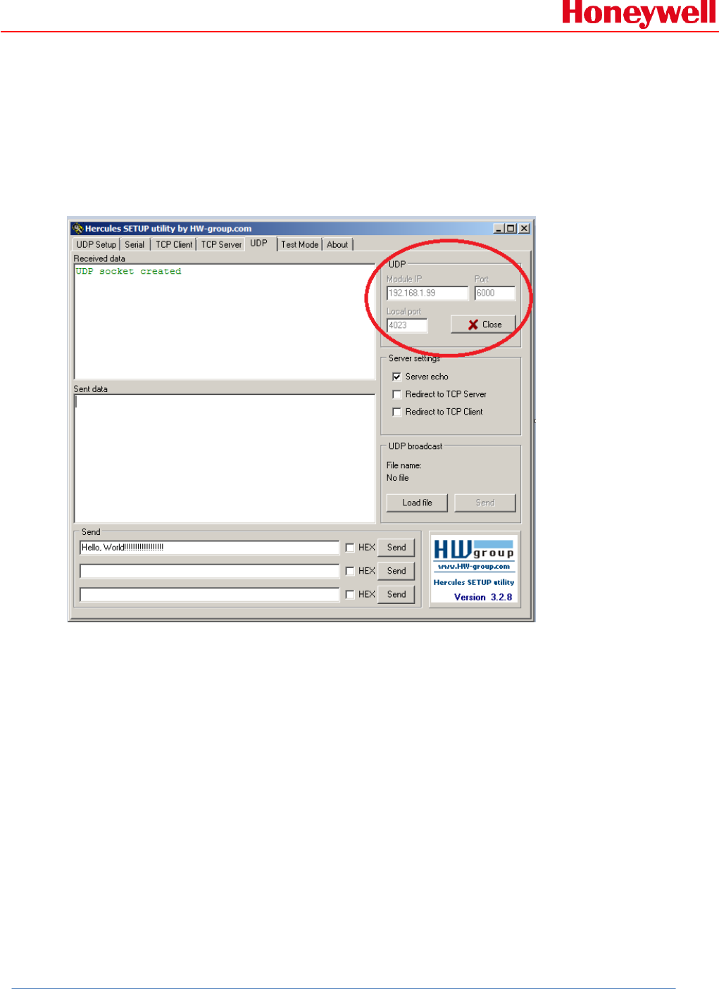
8. How to communication using UDP:
Firstly, use socket tool to create UDP socket which listen on local
port 4023, remote communication node IP: 192.168.1.99, port:
6000, see following picture for detail:
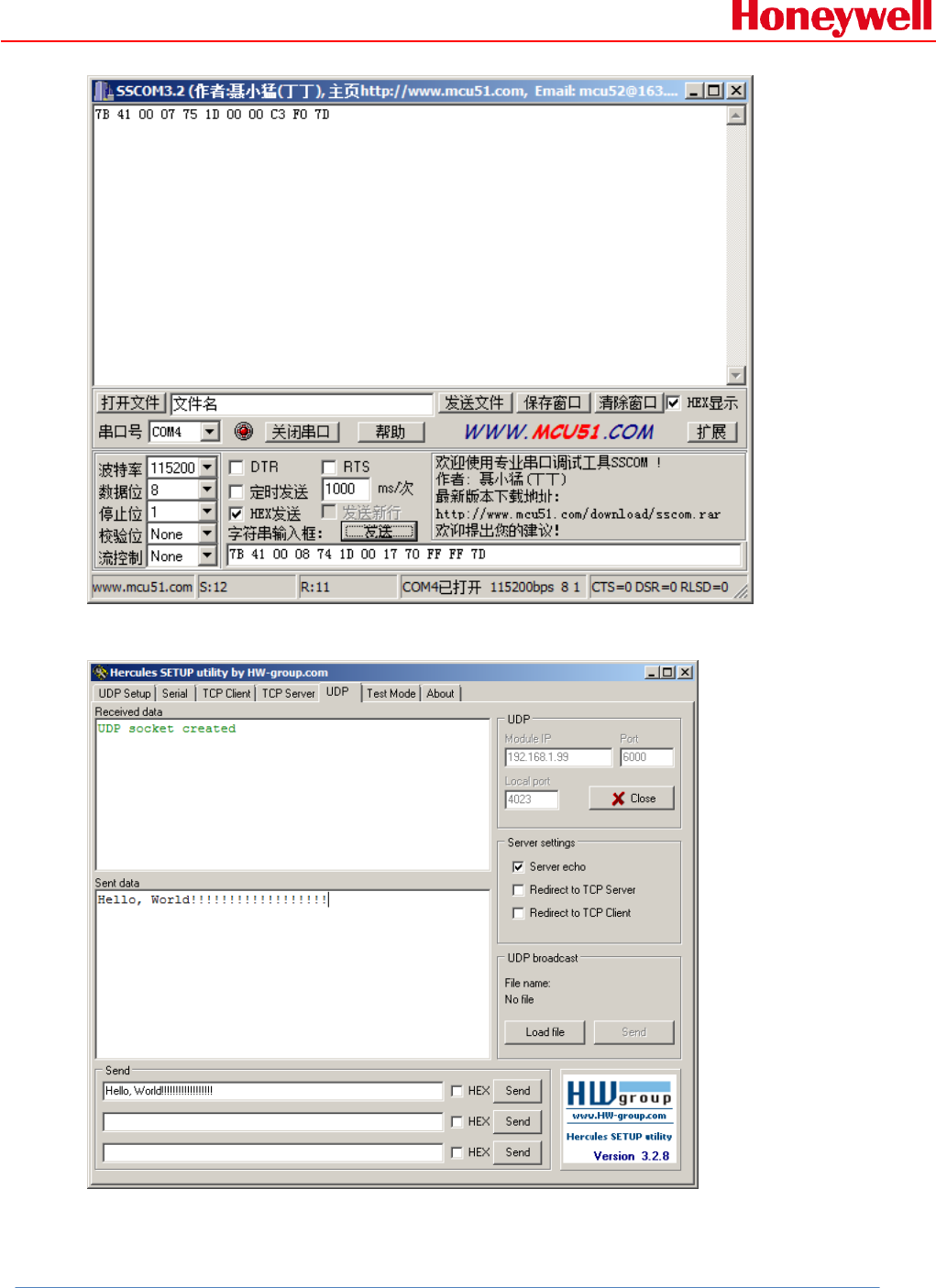
8.1 Receive data packet from UDP server:
1. In order to receive data packet from remote using UDP protocol,
communication via UDP, RMWIFI will need to listen on local port:
6000.
Host command:
7B 41 00 08 74 1D 00 17 70 FF FF 7D
RMWIFI_M3 response:
7B 41 00 07 75 1D 00 00 C3 F0 7D
Example communication sequence:
RAE Systems by Honeywell
Honeywell Confidential and Proprietary Revision –1.0 Page 24 of 29
Copyright © 2015 Honeywell Analytics, All rights reserved.
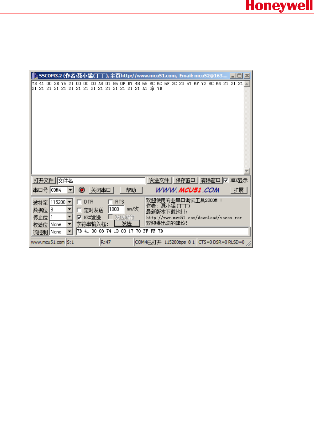
2. Send data packet to RMWIFI as following:
RMWIFI will receive data packet:
RAE Systems by Honeywell
Honeywell Confidential and Proprietary Revision –1.0 Page 25 of 29
Copyright © 2015 Honeywell Analytics, All rights reserved.
7B 41 00 2B 75 21 00 00 C0 A8 01 86 0F B7 48 65 6C 6C 6F 2C 20 57
6F 72 6C 64 21 21 21 21 21 21 21 21 21 21 21 21 21 21 21 21 21 21
A1 37 7D
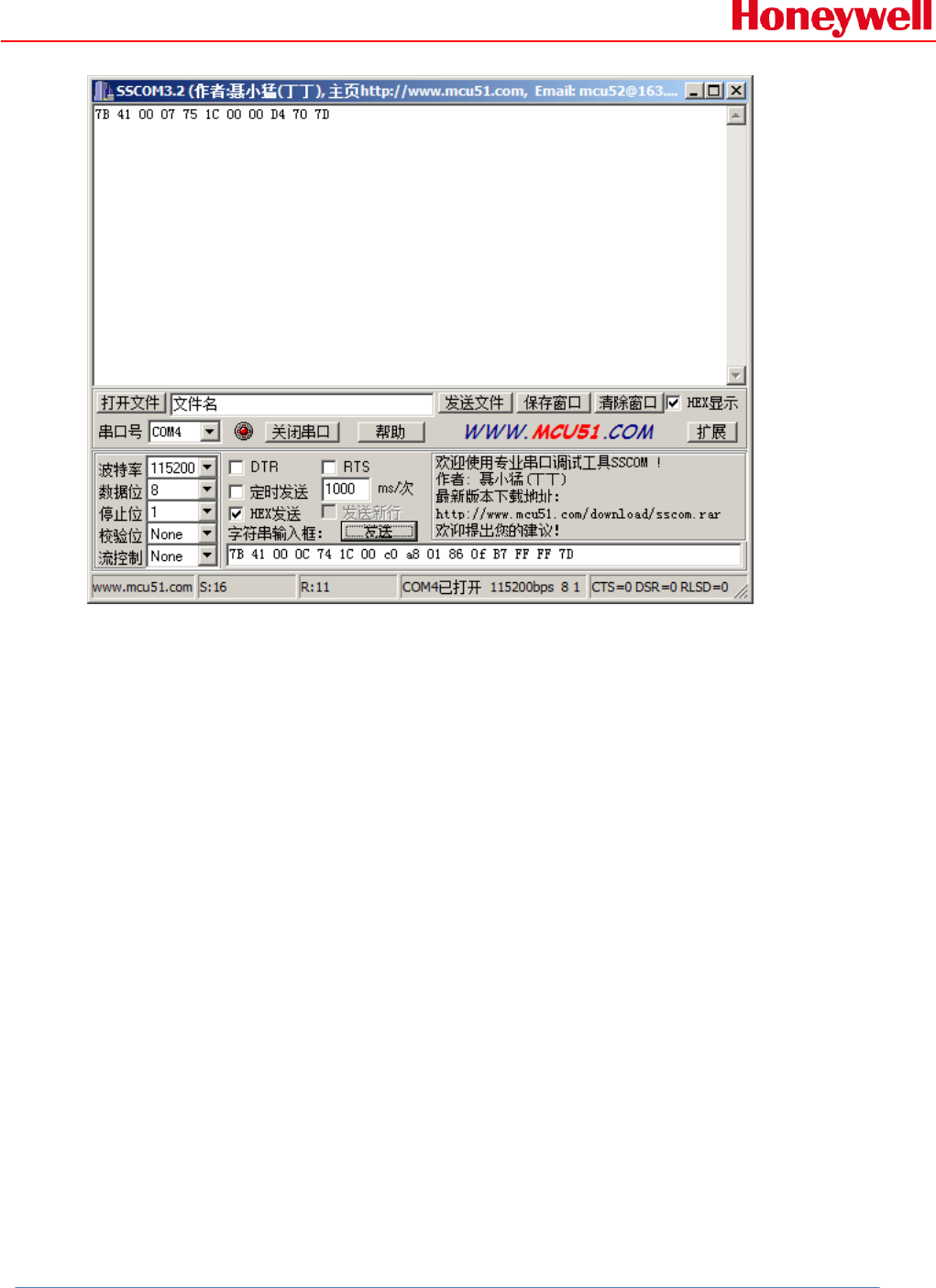
8.2 Send data packet to remote using UDP:
1. RMWIFI will need to create virtual connection to get a
connection ID.
Host command:
7B 41 00 0C 74 1C 00 C0 A8 01 86 0F B7 FF FF 7D
RMWIFI response:
7B 41 00 07 75 1C 00 00 D4 70 7D
Example communication sequence:
RAE Systems by Honeywell
Honeywell Confidential and Proprietary Revision –1.0 Page 26 of 29
Copyright © 2015 Honeywell Analytics, All rights reserved.
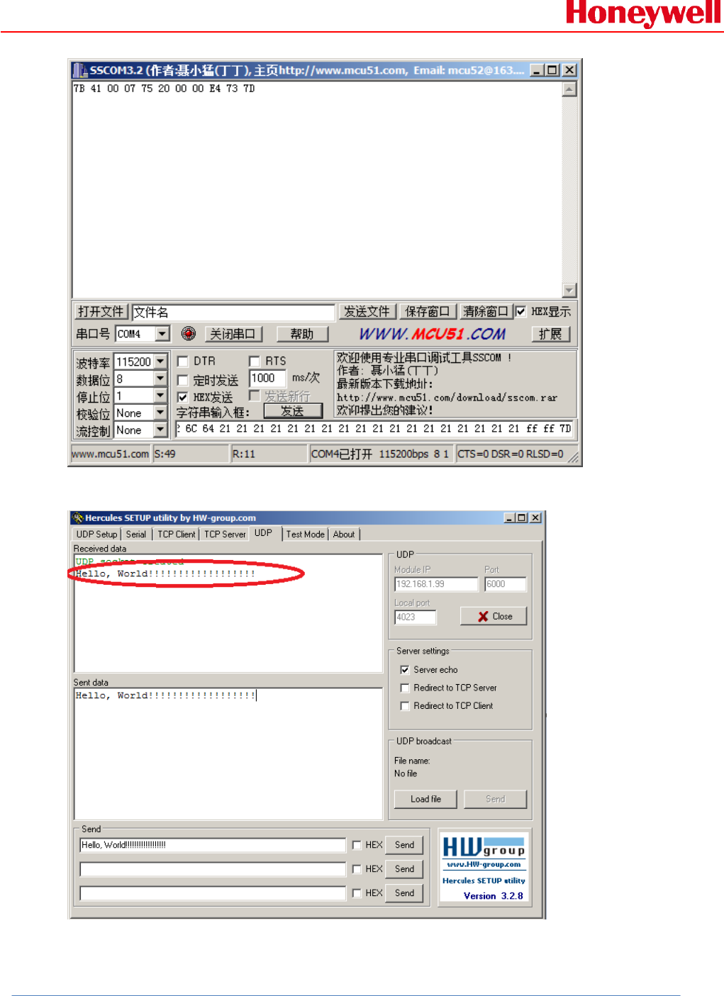
2. Send data packet” Hello, World!!!!!!!!!!!!!!!!!!” to remote:
Host command:
7B 41 00 2C 74 20 00 00 01 C0 A8 01 86 0F B7 48 65 6C 6C 6F 2C 20
57 6F 72 6C 64 21 21 21 21 21 21 21 21 21 21 21 21 21 21 21 21 21
21 ff ff 7D
RMWIFI response:
7B 41 00 07 75 20 00 00 E4 73 7D
Example communication sequence:
RAE Systems by Honeywell
Honeywell Confidential and Proprietary Revision –1.0 Page 27 of 29
Copyright © 2015 Honeywell Analytics, All rights reserved.
Socket test tool will receive the data packet:

RAE Systems by Honeywell
Honeywell Confidential and Proprietary Revision –1.0 Page 28 of 29
Copyright © 2015 Honeywell Analytics, All rights reserved.
9. Reference:
1. 904-E800-xxx RAE Wi-Fi communication Protocol.doc
2. Rev2 EVB board -Datasheet.docx
10. Caution:
This device complies with Part 15 of the FCC Rules. Operation is subject to the following two
conditions: (1) this device may not cause harmful interference, and (2) this device must accept
any interference received, including interference that may cause undesired operation.
Changes or modifications not expressly approved by the party responsible for compliance could
void the user's authority to operate the equipment.
This equipment has been tested and found to comply with the limits for a Class B digital device,
pursuant to part 15 of the FCC Rules. These limits are designed to provide reasonable protection
against harmful interference in a residential installation. This equipment generates uses and can
radiate radio frequency energy and, if not installed and used in accordance with the instructions,
may cause harmful interference to radio communications. However, there is no guarantee that
interference will not occur in a particular installation. If this equipment does cause harmful
interference to radio or television reception, which can be determined by turning the equipment
off and on, the user is encouraged to try to correct the interference by one or more of the
following measures:
-Reorient or relocate the receiving antenna.
-Increase the separation between the equipment and receiver.
-Connect the equipment into an outlet on a circuit different from that to which the receiver is
connected.
-Consult the dealer or an experienced radio/TV technician for help.
MPE Reminding
To satisfy FCC RF exposure requirements, a separation distance of 20 cm or more should be
maintained between the antenna of this device and persons during device operation. To ensure
compliance, operations at closer than this distance is not recommended.
Region Selection
Limited by local law regulations, version for North America does not have region selection option.
Information for the OEM Integrators
This device is intended for OEM integrators only. Please see the full grant of equipment
document for restrictions.
Label Information to the End User by the OEM or Integrators
If the FCC ID of this module is not visible when it is installed inside another device, then the
outside of the device into which the module is into which the module is installed must be label
with "Contains FCC ID: SU3RMWIFI".

RAE Systems by Honeywell
Honeywell Confidential and Proprietary Revision –1.0 Page 29 of 29
Copyright © 2015 Honeywell Analytics, All rights reserved.
For detachable antennas:
This device is tested together with a PCB and a Pole antenna. The client can use an antenna with
the same type of the two antennas, but must make sure that the maximum gain of PCB antenna
is 0dBi and the maximum gain of Pole antenna is 1.5dBi.