RCA 26LA30RQ User Manual LCD TELEVISION Manuals And Guides 1208240L
User Manual: RCA 26LA30RQ 26LA30RQ RCA LCD TELEVISION - Manuals and Guides View the owners manual for your RCA LCD TELEVISION #26LA30RQ. Home:Electronics Parts:Rca Parts:Rca LCD TELEVISION Manual
Open the PDF directly: View PDF ![]() .
.
Page Count: 46
@a
For qualified service personne_ only
Version 1 ,_0
Mode_o
26LASSRQ
Changing Entertainment. Again.
www.rca.com
Revision No. Revision Date Page Description
1 May.24th, 2011 All Initial Release
Version 1.0
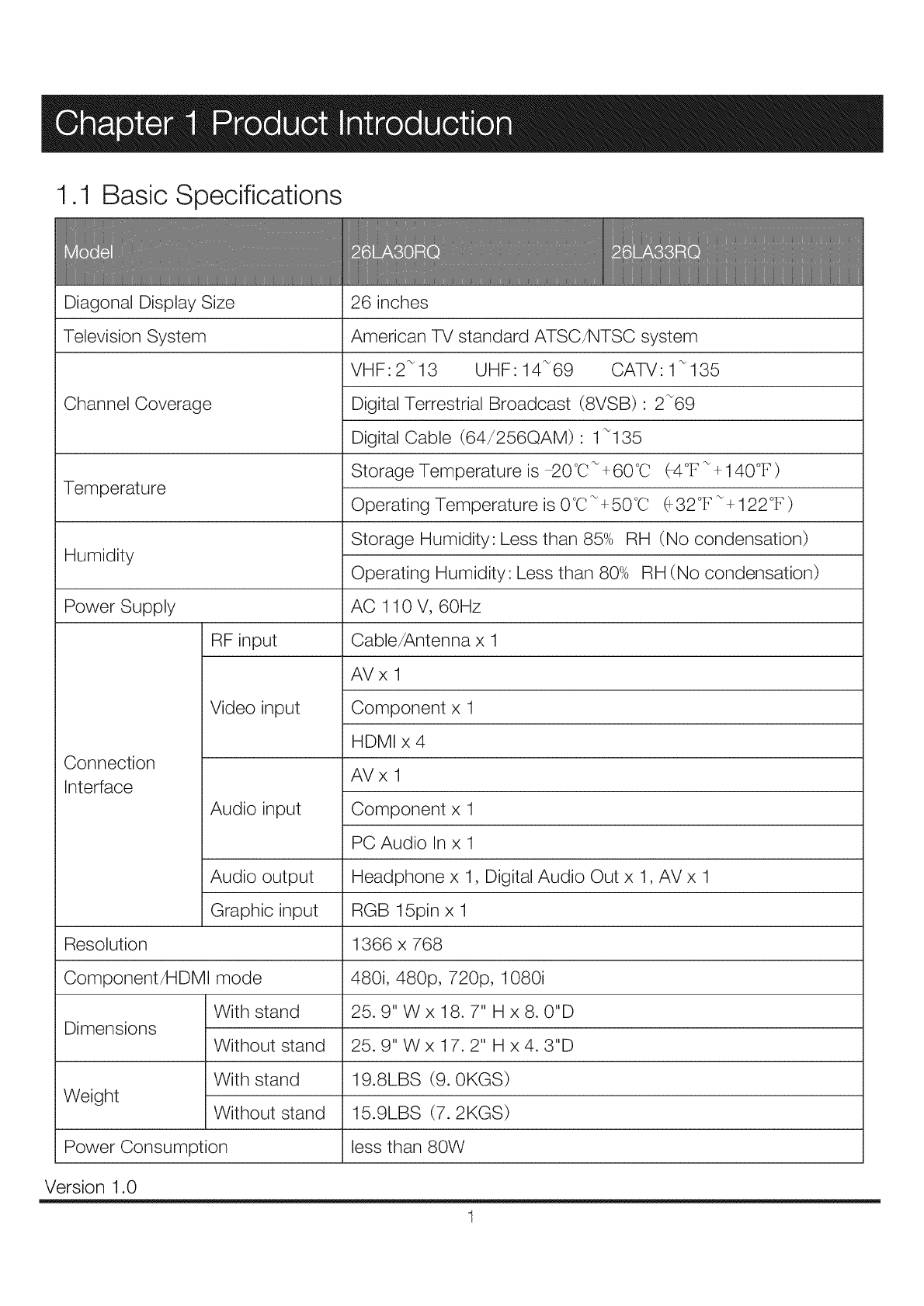
1.1 Basic Specifications
Diagonal Display Size
Television System
Channel Coverage
Temperature
Humidity
Power Supply
RF input
Connection
Interface
Video input
Audio input
Audio output
Graphic input
Resolution
Component/HDMI mode
With stand
Dimensions Without stand
With stand
Weight Without stand
Power Consumption
26 inches
American TV standard ATSC/NTSC system
VHF:2_13 UHF: 14_69 CATV: 1_135
Digital Terrestrial Broadcast (8VSB) : 2_69
Digital Cable (64/256QAM) : 1_135
Storage Temperature is _0°C_ +60°C
Operating Temperature is 0°C_+50°C
(-4°F _+ 140°F)
(_32°F_+ 122°F)
Storage Humidity: Less than 85% RH (No condensation)
Operating Humidity: Less than 80% RH (No condensation)
AC 110 V, 60Hz
Cable/Antenna x 1
AVx 1
Component x 1
HDMI x 4
AVx 1
Component x 1
PC Audio In x 1
Headphone x 1, Digital Audio Out x 1, AV x 1
RGB 15pin x 1
1366 x 768
480i, 480p, 720p, 1080i
25.9" W x 18.7" H x 8. 0"D
25.9" W x 17.2" H x 4.3"D
19.8LBS (9.0KGS)
15.9LBS (7.2KGS)
less than 80W
Version 1.0
1
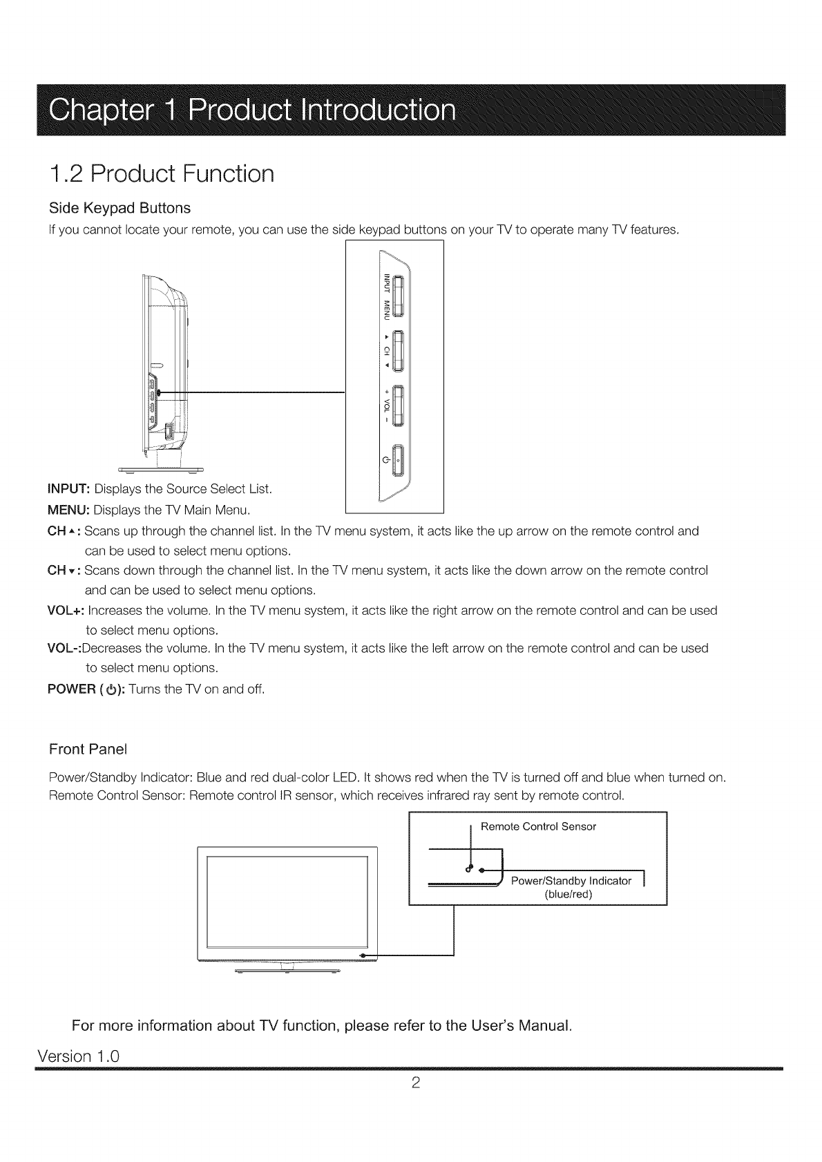
1,2 Product Function
Side Keypad Buttons
If you cannot locate your remote, you can use the side keypad buttons on your TV to operate many TV features.
INPUT: Displays the Source Select List.
MENU: Displays the TV Main Menu.
OH ,, : Scans up through the channel list. In the TV menu system, it acts like the up arrow on the remote control and
can be used to select menu options.
OH ,, : Scans down through the channel list. In the TV menu system, it acts like the down arrow on the remote control
and can be used to select menu options.
VOL+: Increases the volume. In the TV menu system, it acts like the right arrow on the remote control and can be used
to select menu options.
VOL-:Decreases the volume. In the TV menu system, it acts like the left arrow on the remote control and can be used
to select menu options.
POWER (O): Turns the TV on and off.
Front Panel
Power/Standby Indicator: Blue and red dual-color LED. It shows red when the TV is turned off and blue when turned on.
Remote Control Sensor: Remote control IR sensor, which receives infrared ray sent by remote control.
-_ _ _-
I
Remote Control Sensor
'_ Power/Standby Indicator
(blue/red)
For more information about TV function, please refer to the User's Manual.
Version 1.0
2
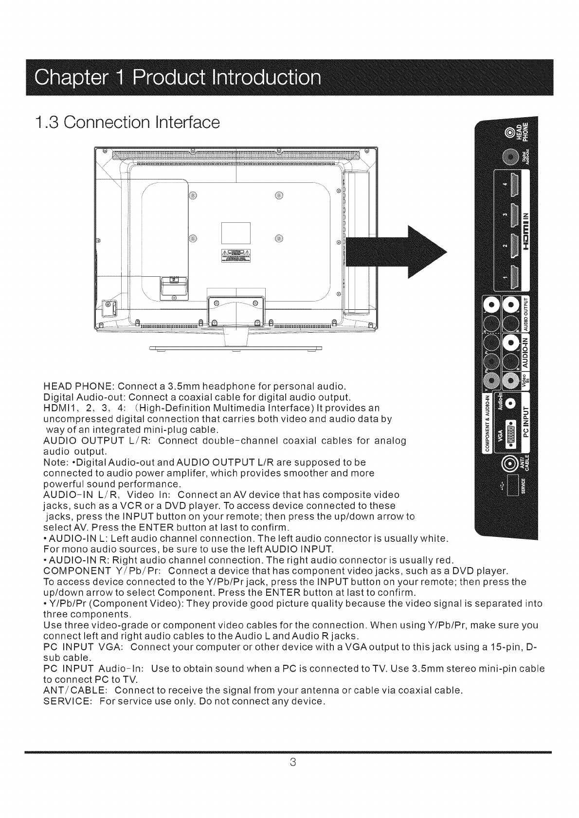
1.3 Connection Interface
HEAD PHONE: Connect a 3.5mm headphone for personal audio.
Digital Audio-out: Connect a coaxial cable for digital audio output.
HDMII, 2, 3, 4: (High-Definition Multimedia Interface) It provides an
uncompressed digital connection that carries both video and audio data by
way of an integrated mini-plug cable.
AUDIO OUTPUT L/R: Connect double-channel coaxial cables for analog
audio output.
Note: .DigitalAudio-out and AUDIO OUTPUT L/R are supposed to be
connected to audio power amplifer, which provides smoother and more
powerful sound performance.
AUDIO-IN L/R, Video In: Connect an AV device that has composite video
jacks, such as a VCR or a DVD player. To access device connected to these
jacks, press the INPUT button on your remote; then press the up/down arrow to
select AV. Press the ENTER button at last to confirm.
• AUDIO-IN L: Left audio channel connection. The left audio connector is usually white.
For mono audio sources, be sure to use the leftAUDIO INPUT.
• AUDIO-IN R: Right audio channel connection. The right audio connector is usually red.
COMPONENT Y/Pb/Pr: Connectadevicethathascomponentvideojacks, such as a DVD player.
To access device connected to the Y/Pb/Prjack, press the INPUT button on your remote; then press the
up/down arrow to select Component. Press the ENTER button at last to confirm.
• Y/Pb/Pr (Component Video): They provide good picture quality because the video signal is separated into
three components.
Use three video-grade or component video cables for the connection. When using Y/Pb/Pr, make sure you
connect left and right audio cables to the Audio L and Audio R jacks.
PC INPUT VGA: Connect your computer or other device withaVGAoutputtothisjackusinga15-pin, D-
sub cable.
PC INPUT Audio-In: Use to obtain sound when a PC is connected to TV. Use 3.5mm stereo mini-pin cable
to connect PC to TV.
ANT/CABLE: Connect to receive the signal from your antenna or cable via coaxial cable.
SERVICE: For service use only. Do not connect any device.
3
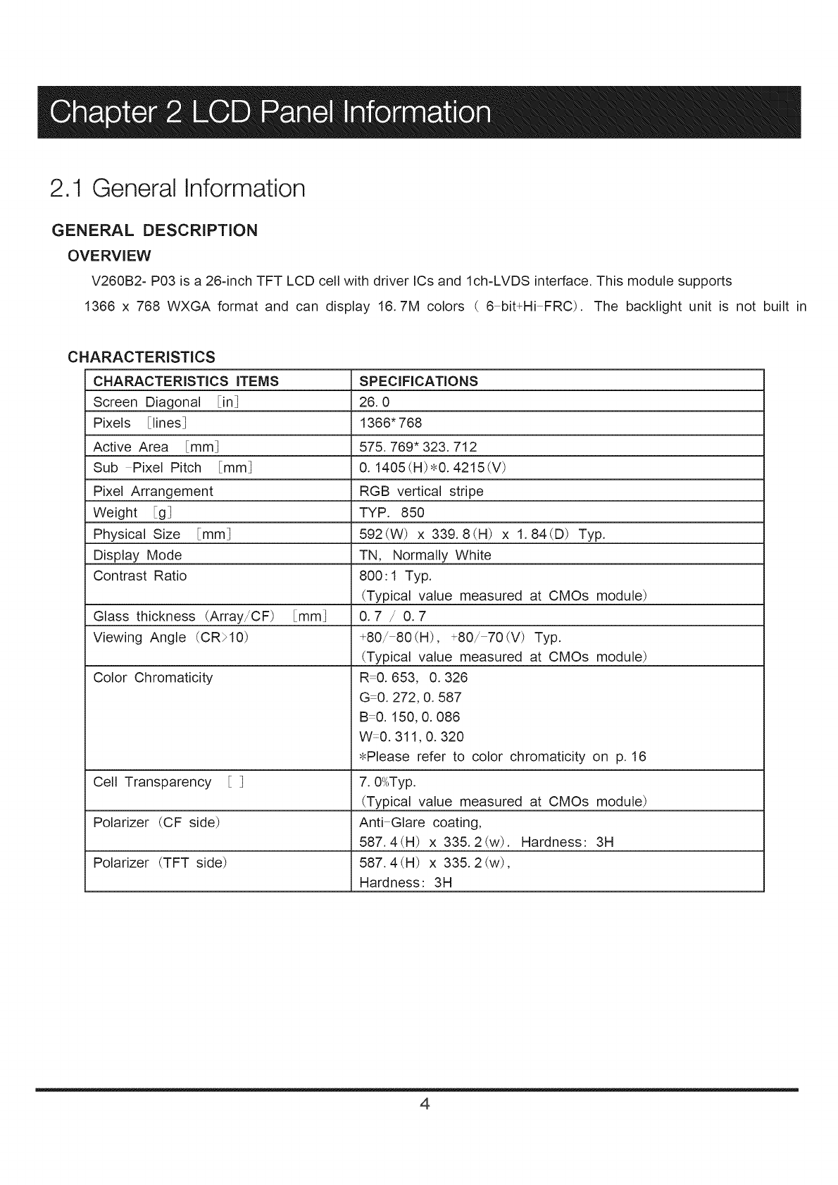
2.1 General Information
GENERAL DESCRIPTION
OVERVIEW
V260B2- P03 is a 26-inch TFT LCD cell with driver ICs and Ich-LVDS interface. This module supports
1366 x 768 WXGA format and can display 16.7M colors ( 6 bit+Hi FRC). The backlight unit is not built in
CHARACTERISTICS
CHARACTERISTICS ITEMS
Screen Diagonal in]
Pixels [lines]
Active Area [mm]
Sub Pixel Pitch [mm]
Pixel Arrangement
Weight g]
Physical Size mm]
Display Mode
Contrast Ratio
Glass thickness (Array/CF) [mm]
Viewing Angle (CR>10)
Color Chromaticity
Cell Transparency ]
Polarizer (CF side)
Polarizer (TFT side)
SPECIFICATIONS
26.0
1366" 768
575.769* 323.712
0. 1405 (H)_0. 4215 (V)
RGB vertical stripe
TYP. 850
592(W) x 339.8(H) x 1.84(D) Typ.
TN, Normally White
800:1 Typ.
(Typical value measured at CMOs module)
0.7/0.7
+80/ 80(H), +80/ 70iV) Typ.
(Typical value measured at CMOs module)
R 0.653, 0.326
GO. 272, 0. 587
B 0. 150, 0. 086
W0.311,0. 320
• Please refer to color chromaticity on p. 16
7.0_,OTyp.
(Typical value measured at CMOs module)
Anti Glare coating,
587.4(H) x 335.2(w). Hardness: 3H
587.4 (H) x 335.2 (w),
Hardness: 3H
4
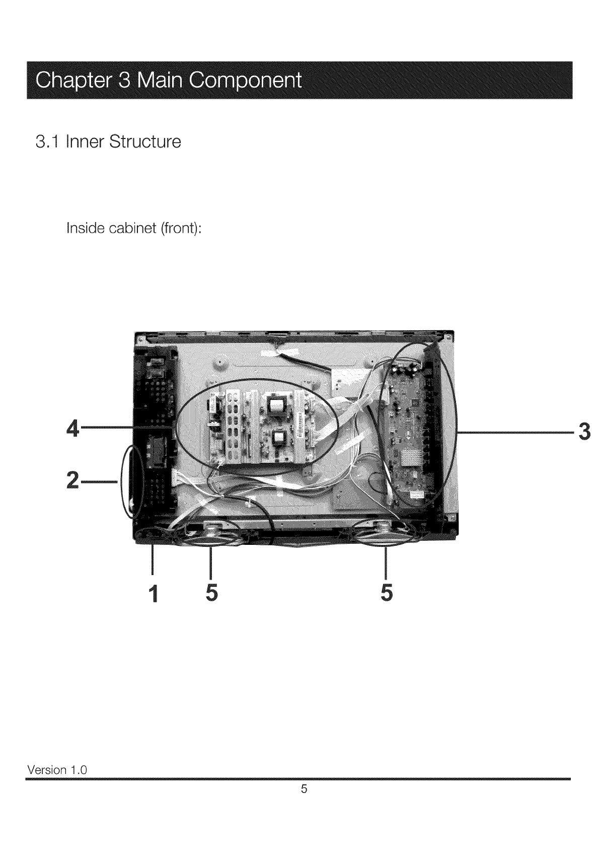
3.1 Inner Structure
Inside cabinet (front)
43
5 5
Version 1.0
5
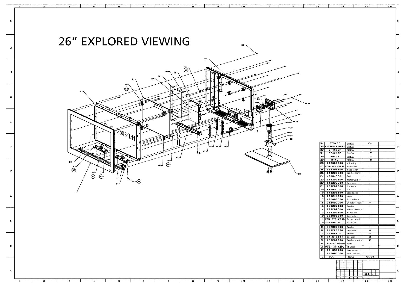
Item List
1 RE3240E010 IR board 22F, 45 x 15 x 1.6 mm (1)
2 RE0340E010 Key board 22F, 106.9 x 11.9 x 1.6 mm (2)
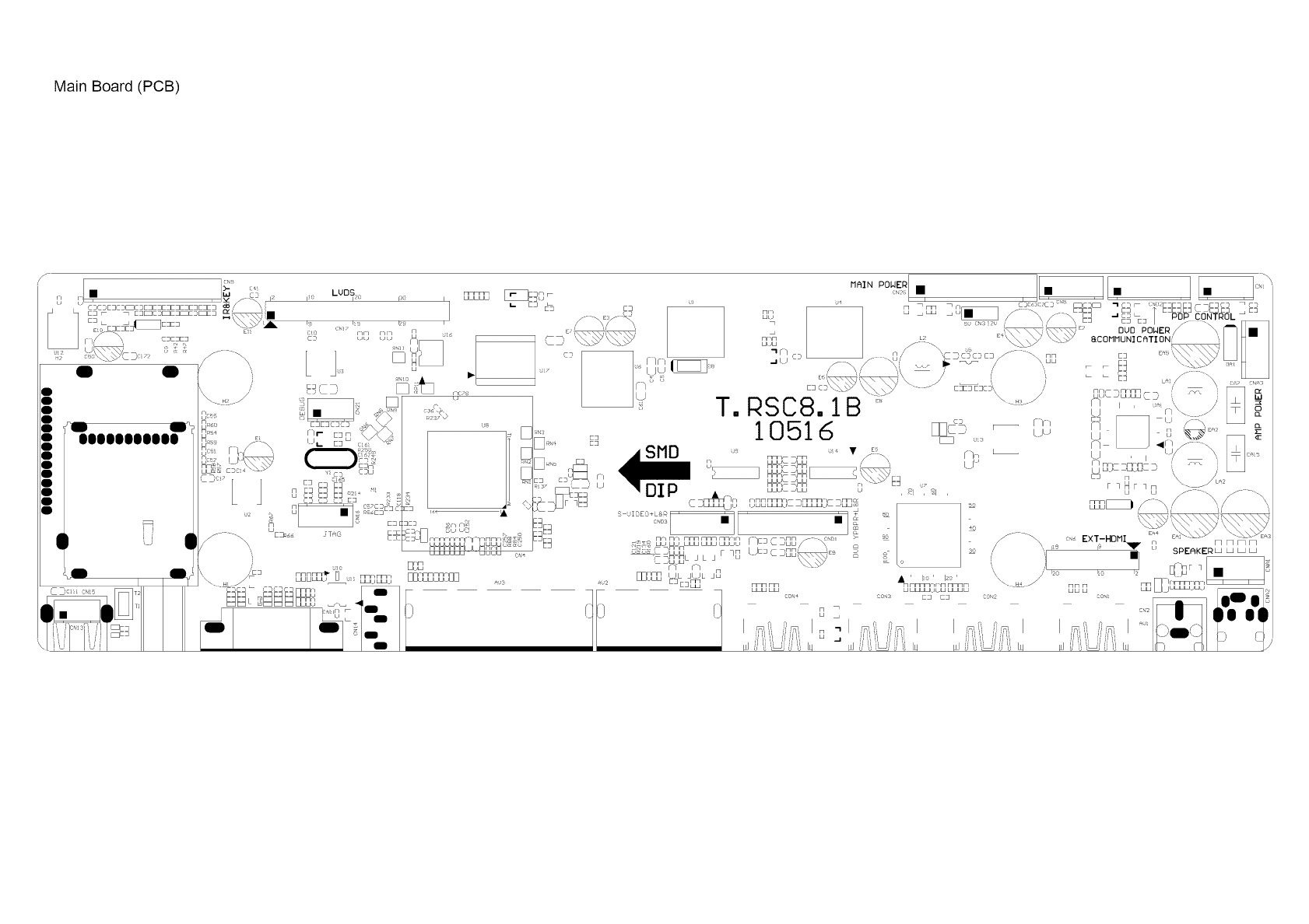
3 RE01TC81XLNA0 Main board T.RSC8.1X
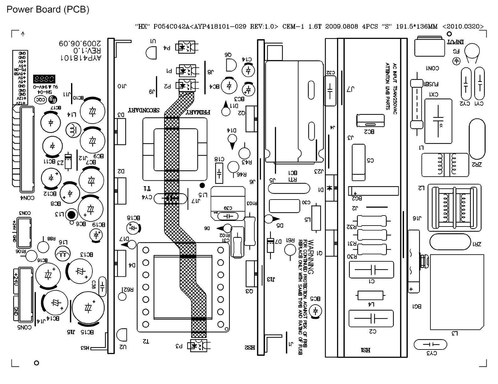
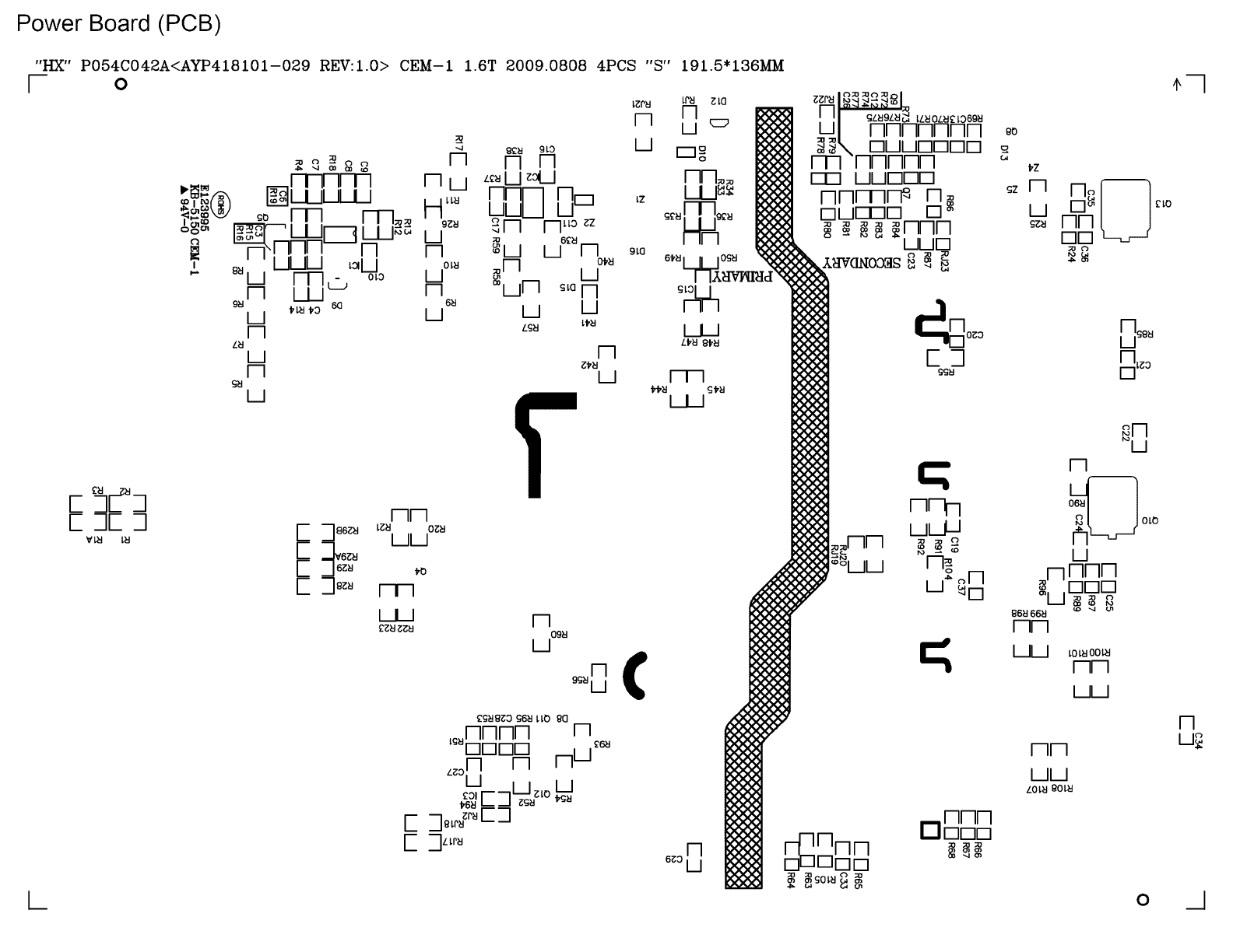
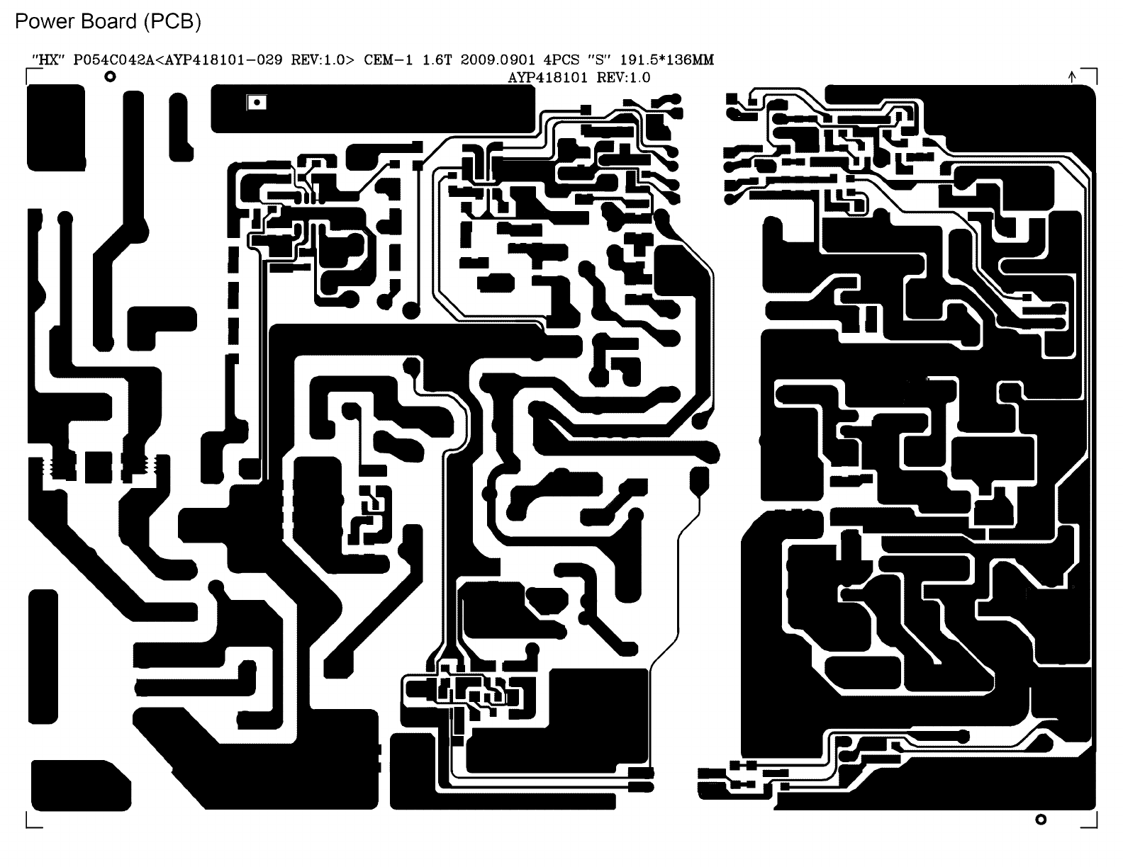
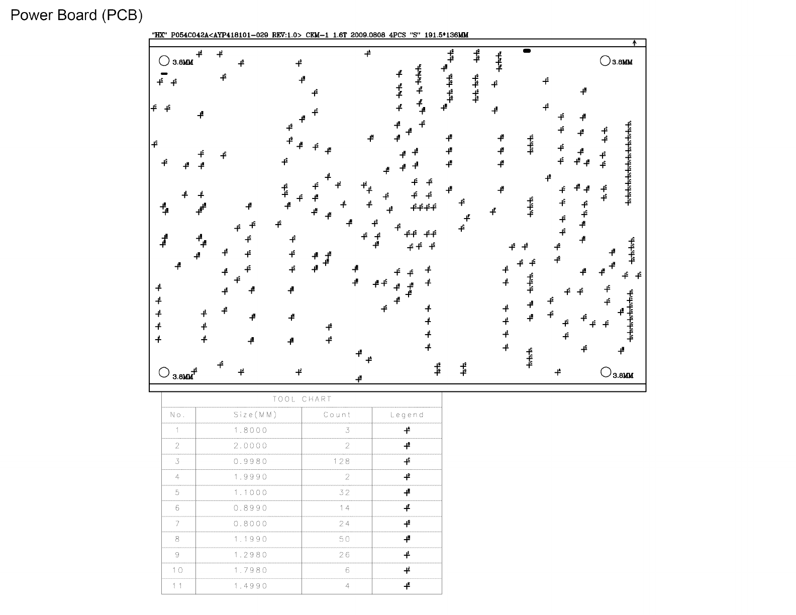
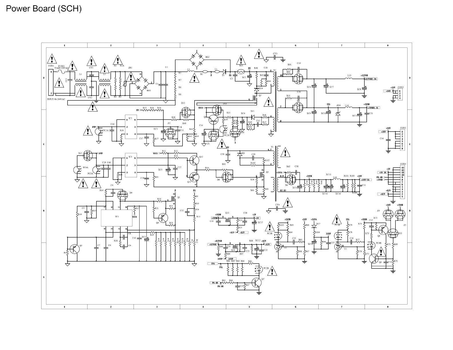
4 RE46Q H 1500 Power board FS P 150-4 H01 150W
5 RE261530458105 Speakers 8Ohm, 10W
Note: (1,2) 22F and dimensions refer to the PCB board.
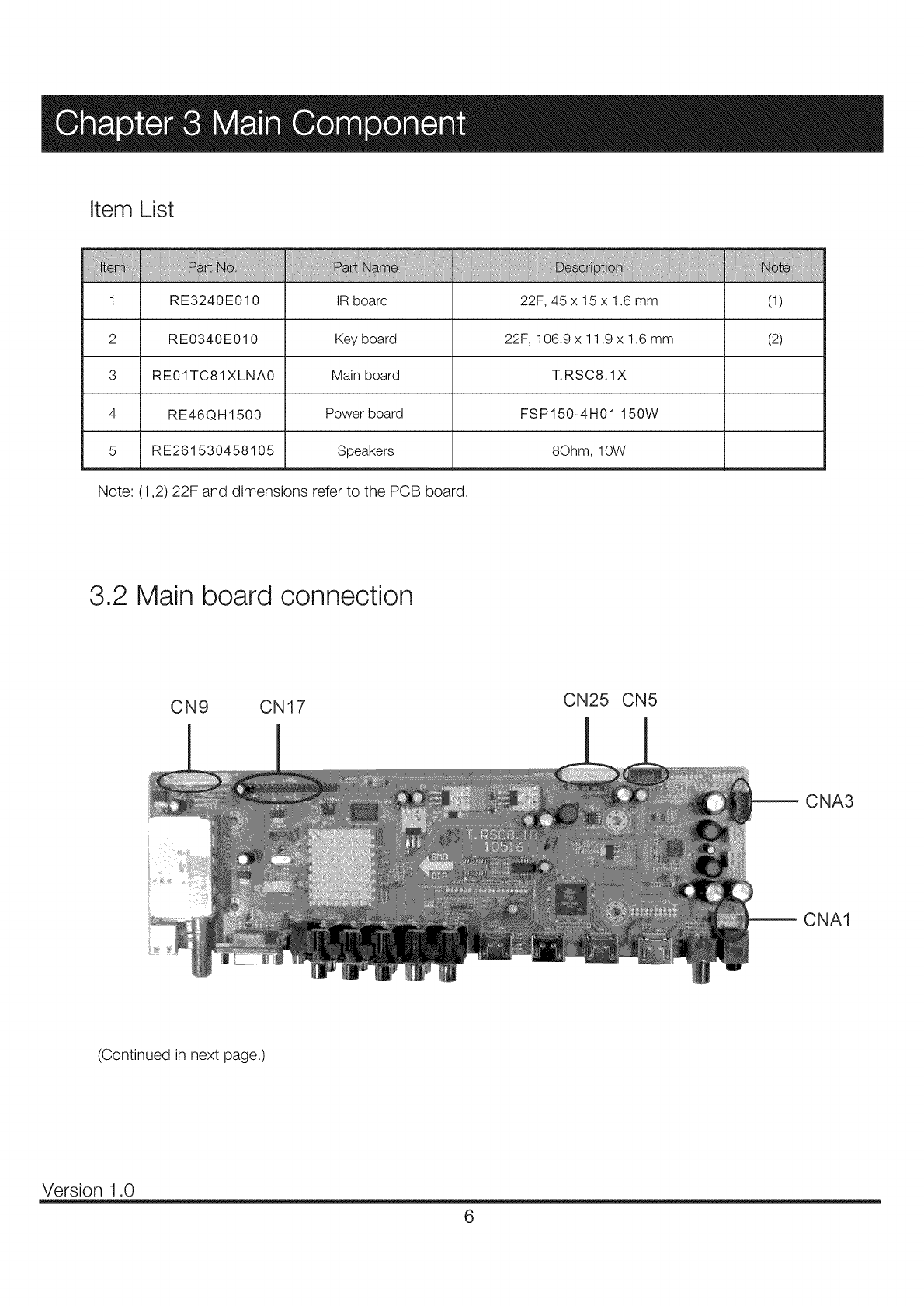
3.2 Main board connection
CN9 CN17 CN25 CN5
CNA3
CNA1
(Continued in next page.)
Version 1.0
6
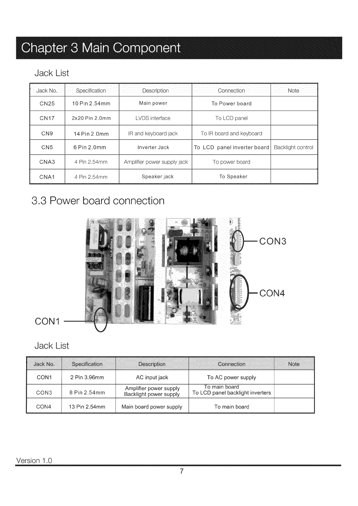
Jack List
Jack No, Specification Description Connection I Note
CN25 10 Pin 2.54mm Main power To Power board
CN17 2x20 Pin 2,0ram LVDS interface To LCD panel
CN9 14 Pin 2.0mm IR and keyboard jack To IR board and keyboard
CN5 6Pin2.0mm inverter Jack To LCD panel inverter board Backtightcontrol
CNA3 4 Pin 2.54mm Amplifier power supply jack To power board
CNA1 4 Pin 2.54mm Speaker jack To Speaker
3.3 Power board connection
CON3
CON4
CON1
Jack List
CON1 2 Pin 3.96mm AC input jack To AC power supply
Amplifier power supply To main board
CON3 8 Pin 2.54mm Backlight power supply To LCD panel backlight inverters
CON4 13 Pin 2.54mm Main board power supply To main board
Version 1.0
7
8
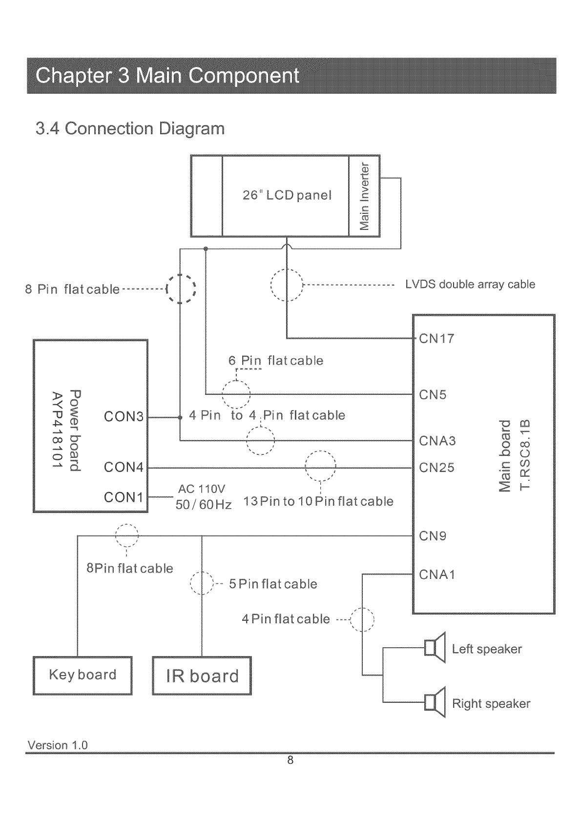
3,4 Connection Diagram
Pin flat cable ......... {
%
©
CON3
@
2 _
o
o_
-_ _ CON4
CON1
8Pin flat cable
Keyboard
26" LCD panel
%
@
@
>
c
Z
6 Pin flatcable
r .....
4Pin to 4.Pin
J _
AC 110V
50/60Hz
flat cable
13Pin to 10Pin flat cable
IR board
5 Pin flatcable
4Pin flat cable °°°,
LVDS double array cable
CN17
CN5
CNA3 o
CN25 _ _
CN9
CNA1
E]_ Left speaker
[_ R_ght
Version 1.0
8

Note: Before opening the cabinet and working on the repairs, please read the troubleshooting and Q&A attached in the
user's manual, which has covered most of the problems caused by unproper using or settings to the TV set. If that does not
work, please carry out the easy troubleshooting before checking or replacing the main parts of the television. The
troubleshooting guides given below base on the situation in which the TV's functions are set and used properly.
Plus, if the easy troubleshooting can not help, please work on the repairing according to the procedures given in chapter 5,
Exception Handles.
4.1 Troubleshooting for Common Use
TV can not be turned on
• Check the connection and condition of wires and inlets that relate to power board, including the AC power inlet, the
power incoming wire, wires between power board and mainboard, etc.
o Check the diagram arround power board to see If there exists a short circuit or creepage.
• The power board may be bad. Please change the board for testing. If it cannot help, refer to the chapter 5 for more
intensive information.
•In addition, the malfunction of LCD panel can cause failure of power on. Please refer to 4.2 Troubleshooting for Displaying
for more information.
Auto turning off
o Check the sleep timer setting.
•Check the surrounding diagram of power board. The problem is most possibly caused by short circuit or wire breakage,
because this kind of malfunctions can cause excessive current, which will make the power board startup self-protection.
The screen goes black after a shorting blink
e If the TV screen can not display after the blink, that means the panel or other parts of equipment is broken (most likely by
unproper input voltage). Ensure the input voltage of every component, and then check the part that is suspected damaged.
o If this problem occurs repeatedly, check the surrounding diagram and connections of panel inverter board. Also, the
blacklight unit and LCD lamps should be checked out.
There exists afterimages after power off
• If the panel can work normally at the other time, it may be caused by bad mainboard. Upgrade to the latest software first,
if that does not work, attempt to change the mainboard.
There exists squeak when TV is working
e IListen to the squeak carefully to make sure where the noise comes from. If it is from speakers, the voice may be caused by
bad speakers. Change them for a try..
• If the noise comes from the inner parts of cabinet, it may be produced by abnormal AC current in power board. Change the
board and check its surrounding circuits for a try.
• Check the routing of wires inside the cabinet to suppress interference.
Version 1.0
9
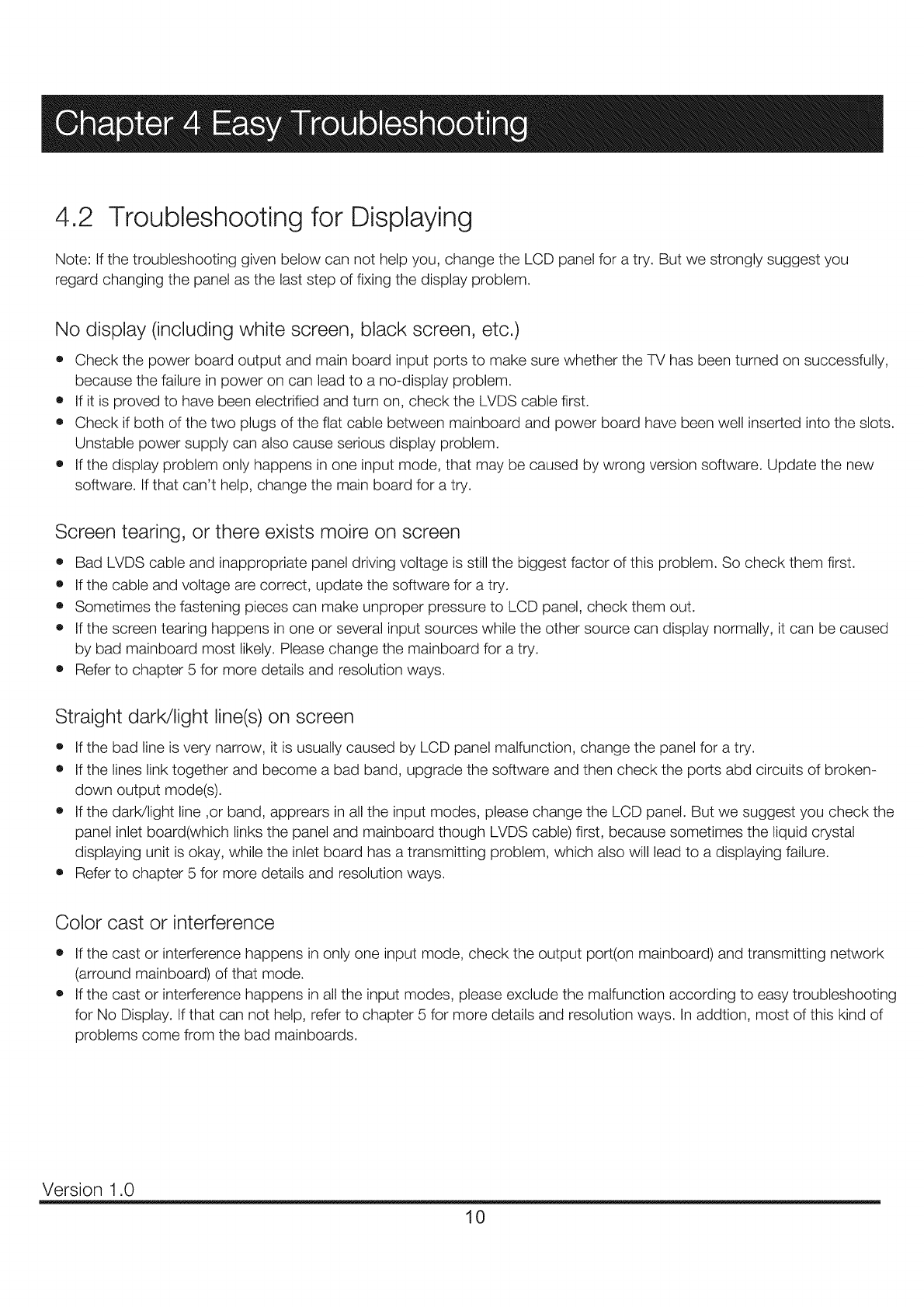
4.2 Troubleshooting for Displaying
Note: If the troubleshooting given below can not help you, change the LCD panel for a try. But we strongly suggest you
regard changing the panel as the last step of fixing the display problem.
No display (including white screen, black screen, etc.)
• Check the power board output and main board input ports to make sure whether the TV has been turned on successfully,
because the failure in power on can lead to a no-display problem.
o If it is proved to have been electrified and turn on, check the LVDS cable first.
• Check if both of the two plugs of the flat cable between mainboard and power board have been well inserted into the slots.
Unstable power supply can also cause serious display problem.
• If the display problem only happens in one input mode, that may be caused by wrong version software. Update the new
software. If that can't help, change the main board for a try.
Screen tearing, or there exists moire on screen
• Bad LVDS cable and inappropriate panel driving voltage is still the biggest factor of this problem. So check them first.
eIf the cable and voltage are correct, update the software for a try.
o Sometimes the fastening pieces can make unproper pressure to LCD panel, check them out.
• If the screen tearing happens in one or several input sources while the other source can display normally, it can be caused
by bad mainboard most likely. Please change the mainboard for a try.
• Refer to chapter 5 for more details and resolution ways.
Straight darWlight line(s) on screen
•If the bad line is very narrow, it is usually caused by LCD panel malfunction, change the panel for a try.
•If the lines link together and become a bad band, upgrade the software and then check the ports abd circuits of broken-
down output mode(s).
eIf the darWlight line ,or band, apprears in all the input modes, please change the LCD panel. But we suggest you check the
panel inlet board(which links the panel and mainboard though LVDS cable) first, because sometimes the liquid crystal
displaying unit is okay, while the inlet board has a transmitting problem, which also will lead to a displaying failure.
• Refer to chapter 5 for more details and resolution ways.
Color cast or interference
•If the cast or interference happens in only one input mode, check the output port(on mainboard) and transmitting network
(arround mainboard) of that mode.
• If the cast or interference happens in all the input modes, please exclude the malfunction according to easy troubleshooting
for No Display. If that can not help, refer to chapter 5 for more details and resolution ways. In addtion, most of this kind of
problems come from the bad mainboards.
Version 1.0
10
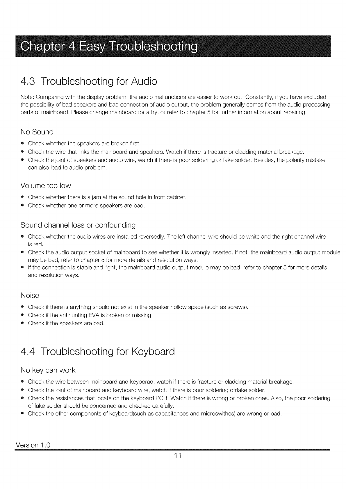
4.3 Troubleshooting for Audio
Note: Comparing with the display problem, the audio malfunctions are easier to work out. Constantly, if you have excluded
the possibility of bad speakers and bad connection of audio output, the problem generally comes from the audio processing
parts of mainboard. Please change mainboard for a try, or refer to chapter 5 for further information about repairing.
No Sound
o Check whether the speakers are broken first.
o Check the wire that links the mainboard and speakers. Watch if there is fracture or cladding material breakage.
• Check the joint of speakers and audio wire, watch if there is poor soldering or fake solder. Besides, the polarity mistake
can also lead to audio problem.
Volume too low
o Check whether there is a jam at the sound hole in front cabinet.
• Check whether one or more speakers are bad.
Sound channel loss or confounding
• Check whether the audio wires are installed reversedly. The left channel wire should be white and the right channel wire
is red.
• Check the audio output socket of mainboard to see whether it is wrongly inserted. If not, the mainboard audio output module
may be bad, refer to chapter 5 for more details and resolution ways.
• If the connection is stable and right, the mainboard audio output module may be bad, refer to chapter 5 for more details
and resolution ways.
Noise
o Check if there is anything should not exist in the speaker hollow space (such as screws).
• Check if the antihunting EVA is broken or missing.
• Check if the speakers are bad.
4.4 Troubleshooting for Keyboard
No key can work
e Check the wire between mainboard and keyborad, watch if there is fracture or cladding material breakage.
• Check the joint of mainboard and keyboard wire, watch if there is poor soldering ofrfake solder.
• Check the resistances that locate on the keyboard PCB. Watch if there is wrong or broken ones. Also, the poor soldering
of fake solder should be concerned and checked carefully.
o Check the other components of keyboard(such as capacitances and microswithes) are wrong or bad.
Version 1.0
11
Keys are sunken
• Check the screws that fasten the keyboard to the cabinet. They may be lost or getting loose.
• The key set may be bad, change them.
There is a reacting delay when operating the keys
o That is usually caused by bad keyboard, change it for a try.
Functions of keys are out of order
o Check the keyboard to see whether there is a short circuit between each soldering joint.
• Check all the resistances on PCB board.
o If a key is supposed to be able to achieve more than one functions, but it can achieve not all of them, that is usually
caused by wrong software. Please update the latest and correct software for a try.
• If you can't ensure where the problem comes from, change the keyboard for a try. If that still can't help, refer to chapter 5
for more details and resolution ways.
4.5 Troubleshooting for Remote Control
Note: If the troubleshooting can not help, please change the RC board. If that still can't solve the problem, please refer to
chapter 5 for more details and resolution ways with a will to mainboard repairing.
The RC (remote control, the same below) does not work
• Check the wire between mainboard and RC board, watch if there is fracture or cladding material breakage.
• Check the joint of mainboard and RC board wire, watch if there is poor soldering or fake solder. Also, the short circuit
can lead to this problem, too.
o Check the infrared senser that locates on the keyboard PCB. Watch if it is wrong or broken. Also, the poor soldering of
fake solder should be concerned and checked carefully.
• Check the other components of RC board are wrong or bad.
The LCD displays light in wrong color
• The short circuit is the most probable causation factor of this proble. Check the wire and joints for a judgement.
• Check the cable that links mainboard and RC board, watch if it is inserted with wrong location(similar with left-right channel
wire fault for audio).
o Check the LCD assembling, watch if its pins are in wrong location.
Version 1.0
12
Note: The exception handles are prepared for qualified personal only.
5.1 Display Exceptions
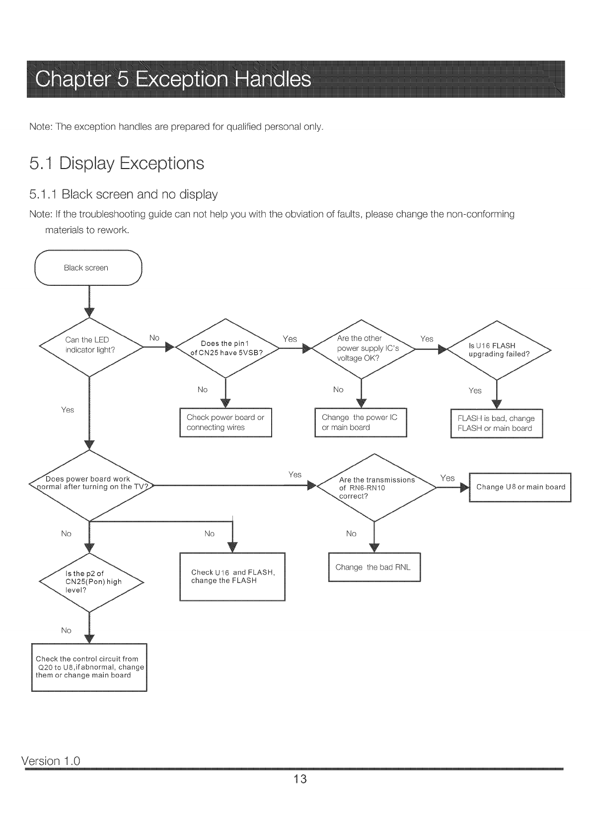
5,1.1 Black screen and no display
Note: If the troubleshooting guide can not help you with the obviation of faults, please change the non-conforming
materials to rework.
Can the LED No Yes the other Yes
Does the pin1 is UI6 FLASH
indicator light? of CN25 have 5VSB? power supply IC's
voltage OK? upgrading failed?
Yes
Check power board or
connecting wires
_ower board work
iormal after turning on the
No
Is the p2 of
< CN25(Pon) high
Ch20 _t hu8_i_n tbr°;cimrC_itcft[°n_ e 1
them or change main board m
1
CheckU16 and FLASH,
change the FLASH
Yes
No Yes
I hange the power IC 1
or main board FLASH is bad, change
FLASH or main board
Change the bad RNL 1
Change U8 or main board
Version 1.0
13
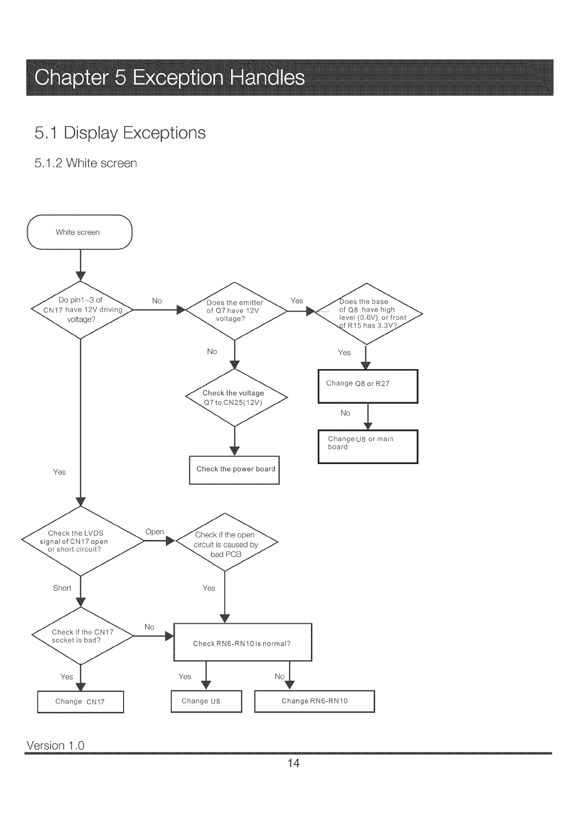
5,1 DispJay Exceptions
5.1.2 White screen
- White screen "_
Do pin1-3 of
CN17have 12Vdrvi _
voltage?
No
Yes
No
<.. Check the voltage >
Check the power board
i Change Q8 or R27
_o___
i ChangeU8 or main
board
i
i
Check the LVDS
signal of CN17 open
or s_ort c rcu t?
if the open
circuit is caused by
bad PCB
Sho_ Yes
Check RN6_RN10 is normal? 1
$ 4
ChangeU8 1 ChangeRN6-RN10 1
Version 1.0
14
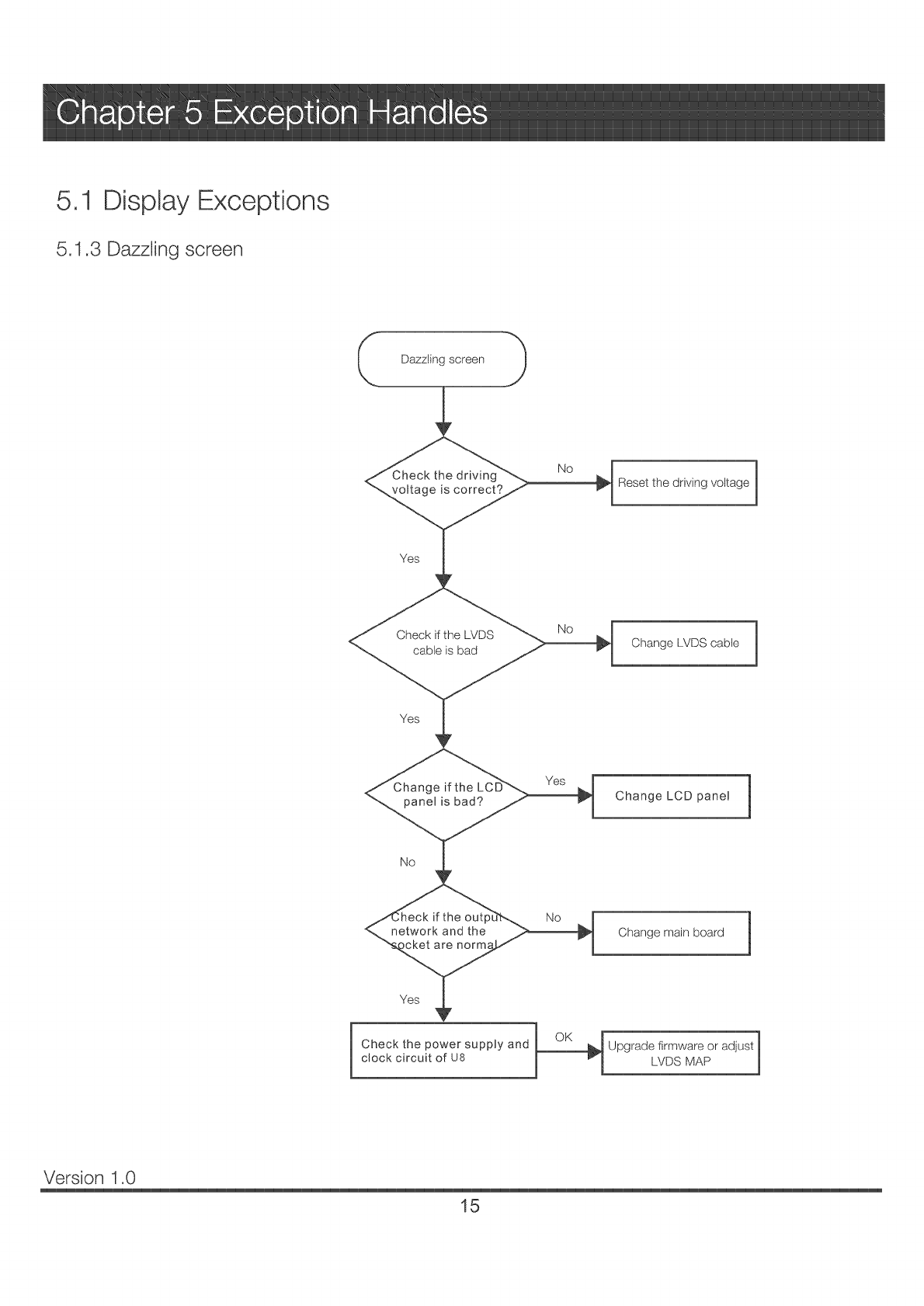
5.1 Display Exceptions
5.1.3 Dazzling screen
No
_ Reset the driving voltage
Check if the LVDS
cable is bad
No
Change LVDS cable
Yes
e if the Yes ]
panel is bad? Change LCD panel J
No
Change main board 1
¢hk" t
Check the power supply and _Upgrade firmware or adjust
clock circuit of U8 P7 LVDS MAP
Version 1.0
15
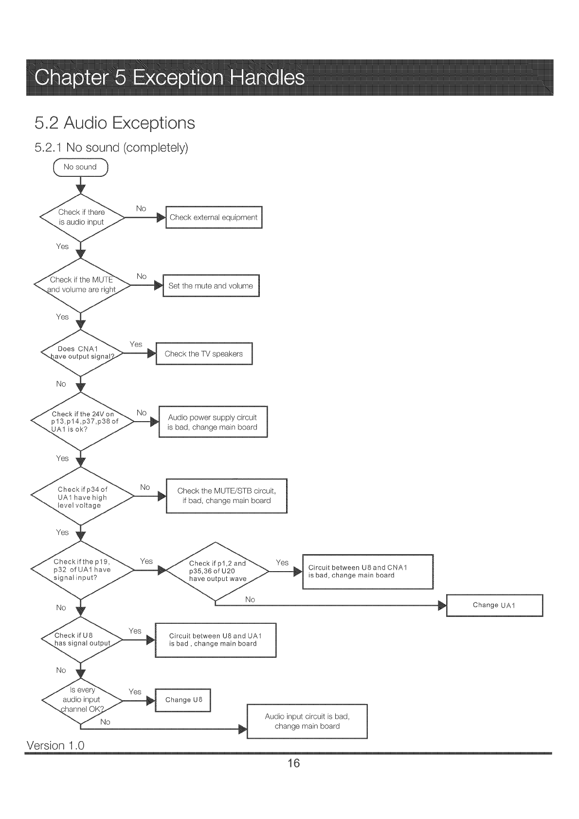
5,2 Audio Exceptions
5,2.1 No sound (completely)
No sound
Check if there
is audio input
Yes
<_, volume are
Yes
Does CNA1
_ve output signa
No
if the
p13,p14,p37,p38 of
UA1 is ok?
Yes
Check ifp34of
UAI have high
tevel voltage
Yes
Checkifthe plg,
p32 of UA1 have
signal input?
No
No
No
Yes
No
1
Check external equipment
Set the mute and volume 1
Check the TV speakers 1
Audio power supply circuit 1
is bad, change main board 1
Check the MUTB/STB circuit,
if bad, change main board
Yes Check if p1,2 Yes
p35,36 of U20
have output wave
No
Circuit between U8 and CNA1
is bad, change main board
Version 1.0
Circuit between U8 and UA1
is bad, change main board
Change U8
Audio input circuit is bad,
change main board
Change UA1 1
16
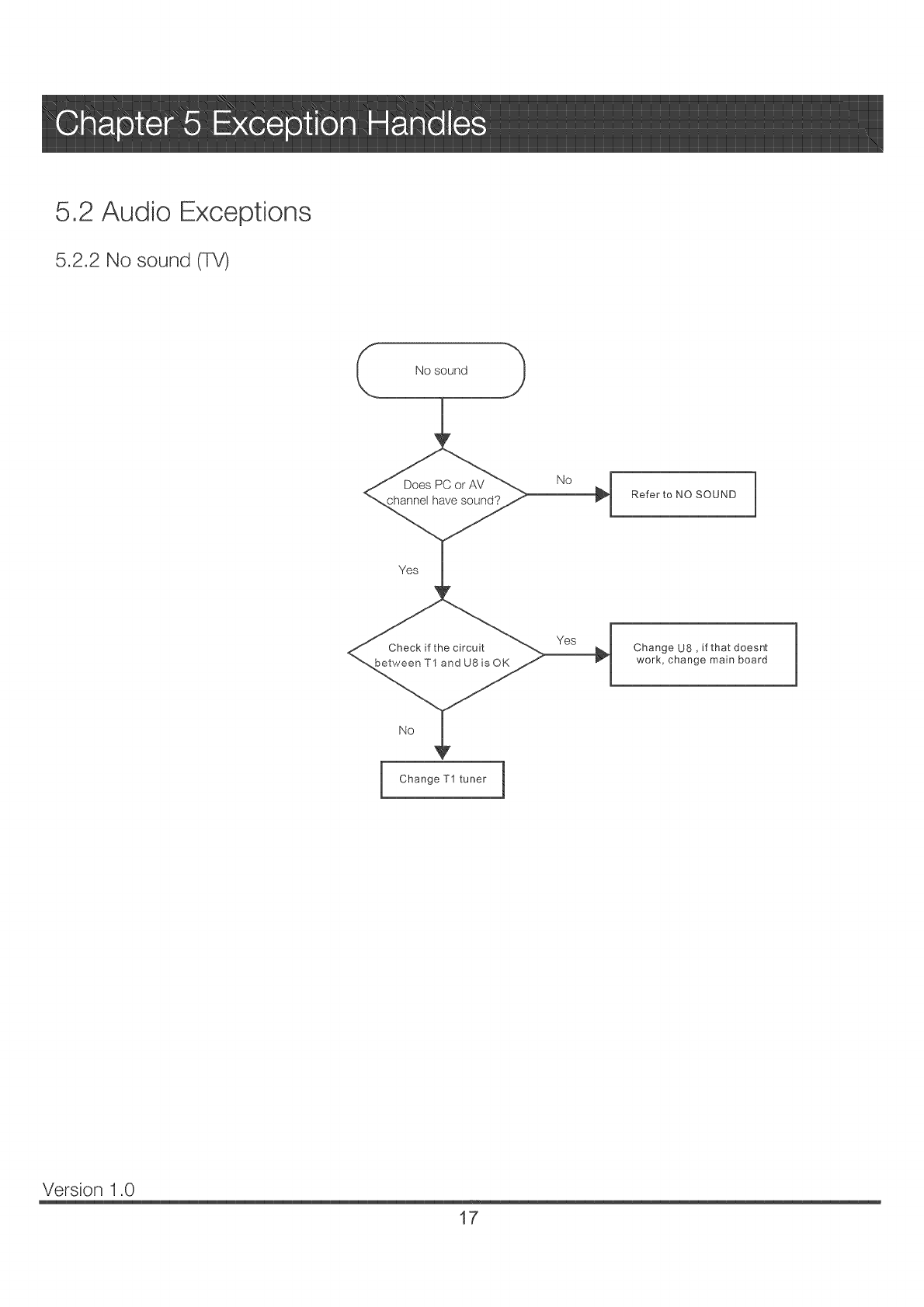
5,2 Audio Exceptions
5.2.2 No sound (TV)
Refer to NO SOUND 1
Yes
Check if the circuit
between T1 and U8 is OK
Yes Change U8, if that doesnt
work, change main board
No
Change T1 tuner 1
Version 1.0
17
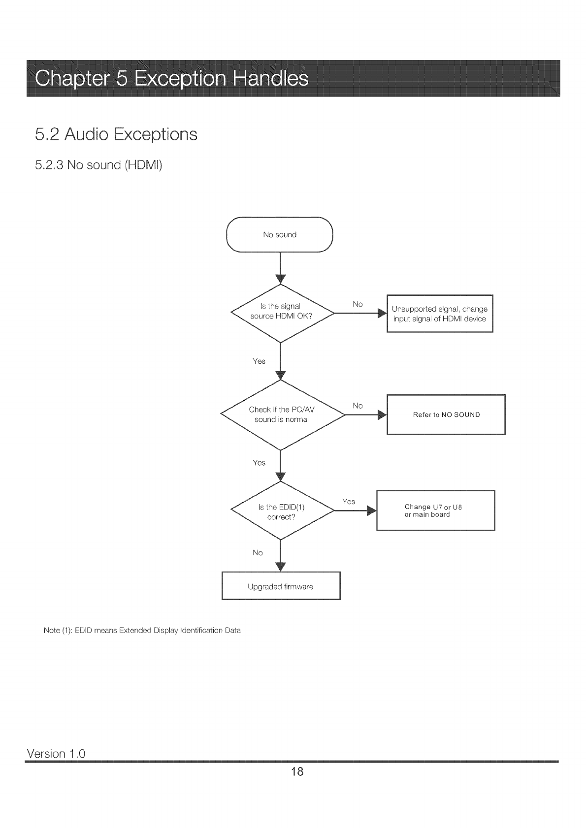
5.2 Audio Exceptions
5.2.3 No sound (HDMI)
1
Is the signal No _]]_1
source HDMI OK? 1
Unsupported signal, change
input signal of HDMI device
Yes
Check if the PC/AV
sound is normal
No
Refer to NO SOUND
Yes
<_ Is the EDID(1) Yes>_l _
Upgraded firmware
Change U7 or U8
or main board
Note (I): EDtD means Extended Display Identification Data
Version 1.0
18
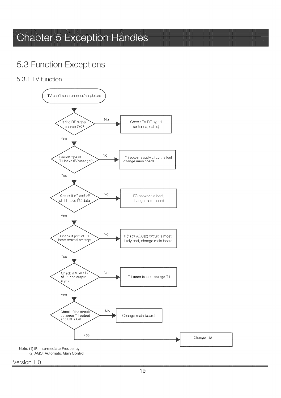
5.3 Function Exceptions
5.3.1 TV function
rV can't scan channel/no picture_'y_
Check if p7 No
of T1 have 120data
Check -['v' RF signal
(antenna, cable)
TI power supply circuit is bad
change main board
I2C network is bad,
change main board
Yes
Check if p12 ofT1
have normal voltage
No IF(l) or AGC(2) circuit is most
likely bad, change main board
Yes
ofT1 has output
signal
No
T1 tuner is bad, change T1
Yes
Check if
between T1 output
U8 is OK
J
Yes
Note: (1) iF: Intermediate Frequency
(2) AGC: Automatic Gain Control
No
Change main board
Change U8 1
Version 1.0
19
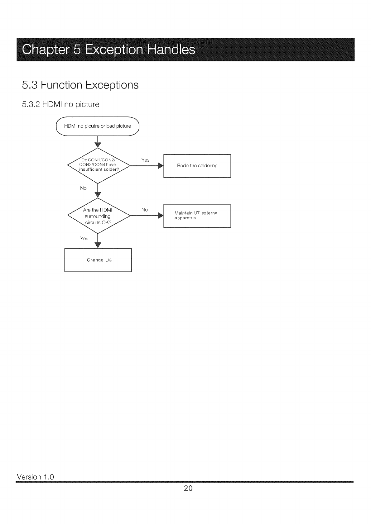
5.3 Function Exceptions
5.3.2 HDMI no picture
HDMI no picutre or bad picture_'_
No
i Change U8 1
Redo the soldering
No ha Maintain u7 external
apparatus
Version 1.0
20
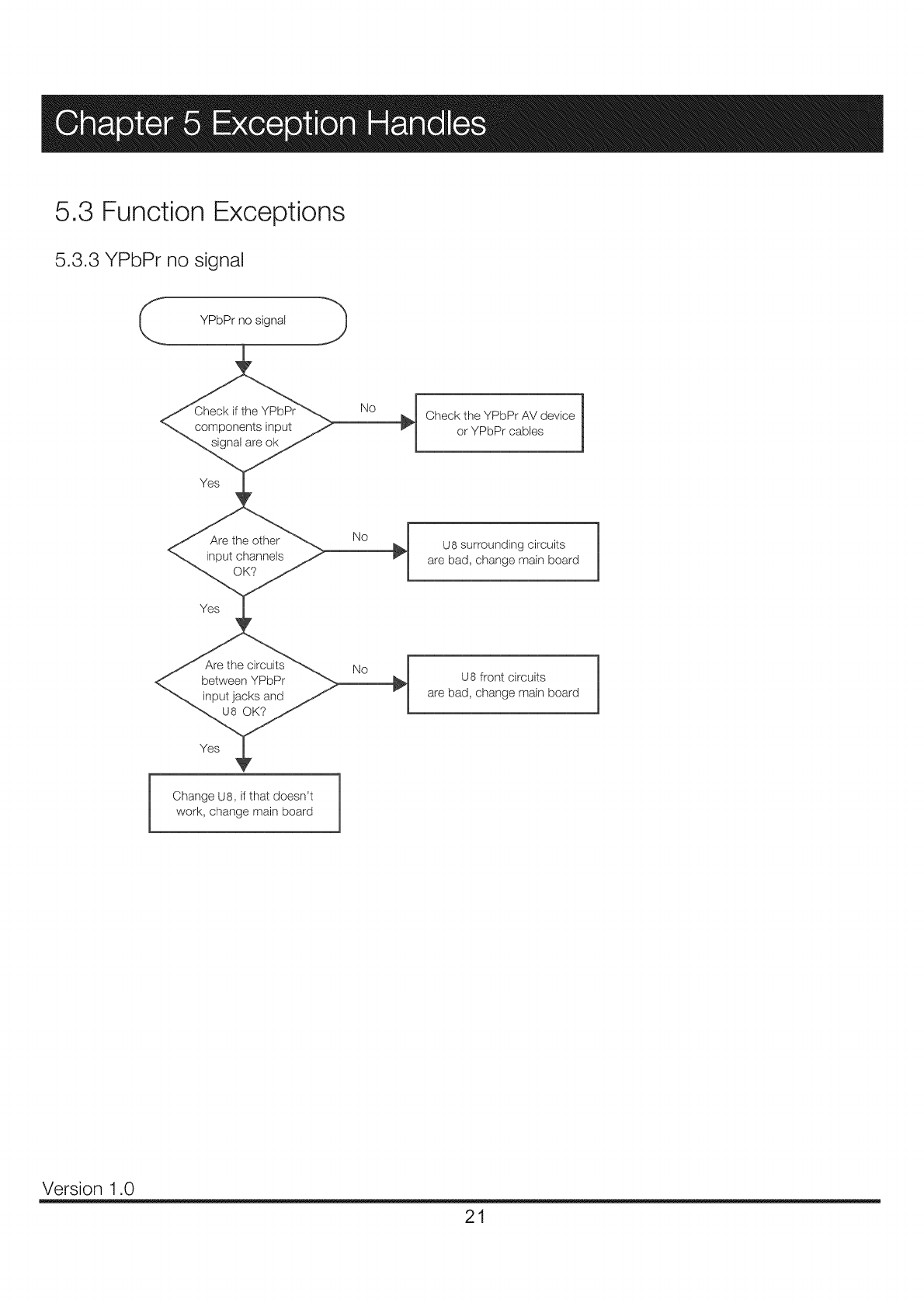
5.3 Function Exceptions
5.3.3 YPbPr no signal
YPbPr no signal J
work, change main board
]
Check the YPbPr AV device |
J
or YPbPr cables
U8 surrounding circuits
are bad, change main board
U8 front circuits
are bad, change main board
Version 1.0
21
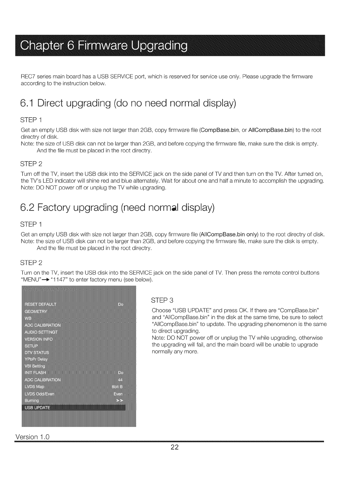
REC7 series main board has a USB SERVICE port, which is reserved for service use only. Please upgrade the firmware
according to the instruction below.
6.1 Direct upgrading (do no need normal display)
STEP1
Get an empty USB disk with size not larger than 2GB, copy firmware file (CompBase.bin, or AlICompBase.bin) to the root
directry of disk.
Note: the size of USB disk can not be larger than 2GB, and before copying the firmware file, make sure the disk is empty.
And the file must be placed in the root directry.
STEP 2
Turn off the TV, insert the USB disk into the SERVICE jack on the side panel of TV and then turn on the TV. After turned on,
the TV's LED indicator will shine red and blue alternately. Wait for about one and half a minute to accomplish the upgrading.
Note: DO NOT power off or unplug the TV while upgrading.
6.2 Factory upgrading (need normal display)
STEP1
Get an empty USB disk with size not larger than 2GB, copy firmware file (AIICompBase.bin only) to the root directry of disk.
Note: the size of USB disk can not be larger than 2GB, and before copying the firmware file, make sure the disk is empty.
And the file must be placed in the root directry.
STEP 2
Turn on the TV, insert the USB disk into the SERVICE jack on the side panel of TV. Then press the remote control buttons
"MENU"--_ "1147" to enter factory menu (see below).
STEP 3
Choose "USB UPDATE" and press OK. Ifthere are "CompBase.bin"
and "AlICompBase.bin" in the disk at the same time, be sure to select
"AIICompBase.bin" to update. The upgrading phenomenon is the same
to direct upgrading.
Note: DO NOT power off or unplug the TV while upgrading, otherwise
the upgrading will fail, and the main board will be unable to upgrade
normally any more.
Version 1.0
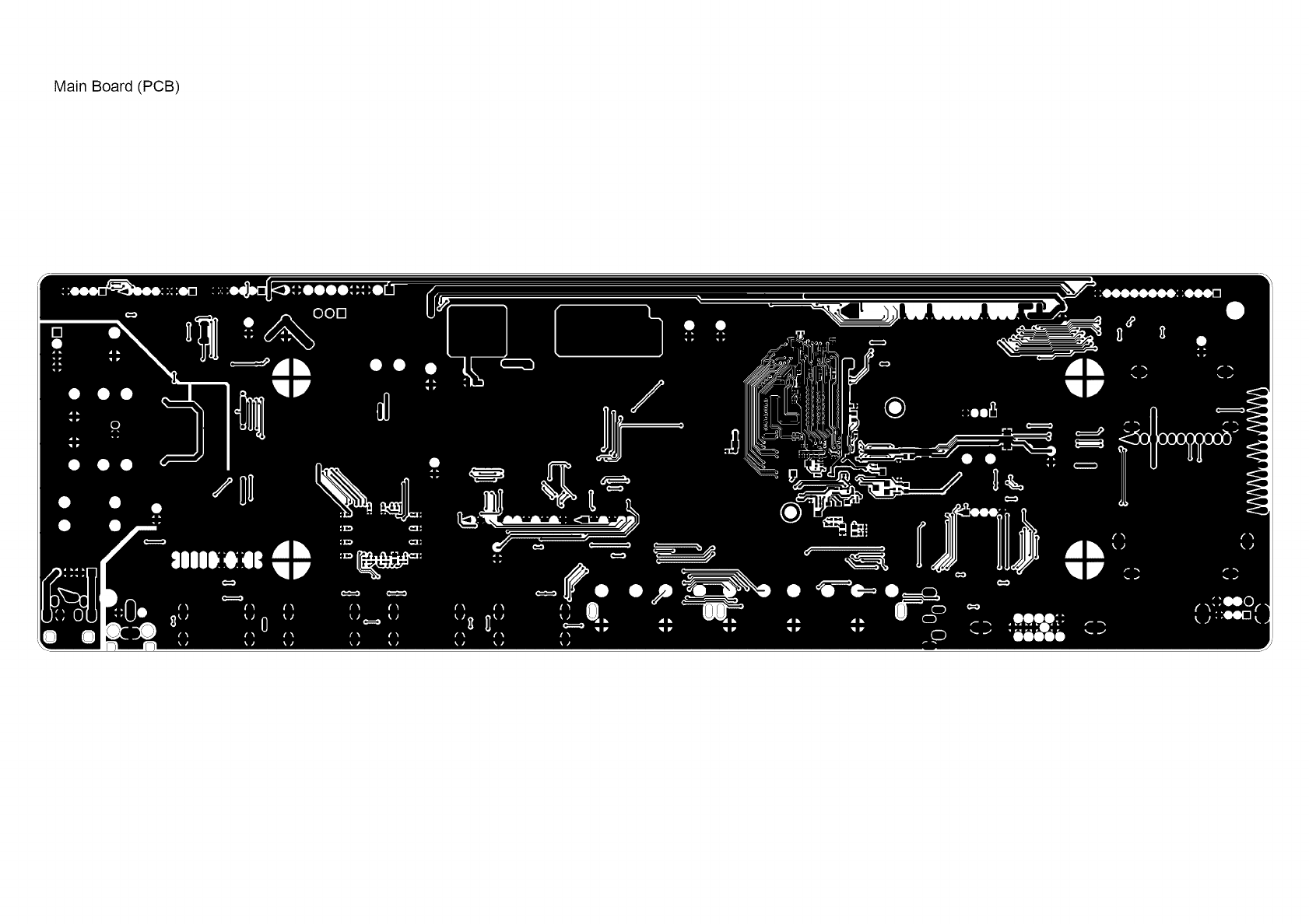
Main Board (PCB)
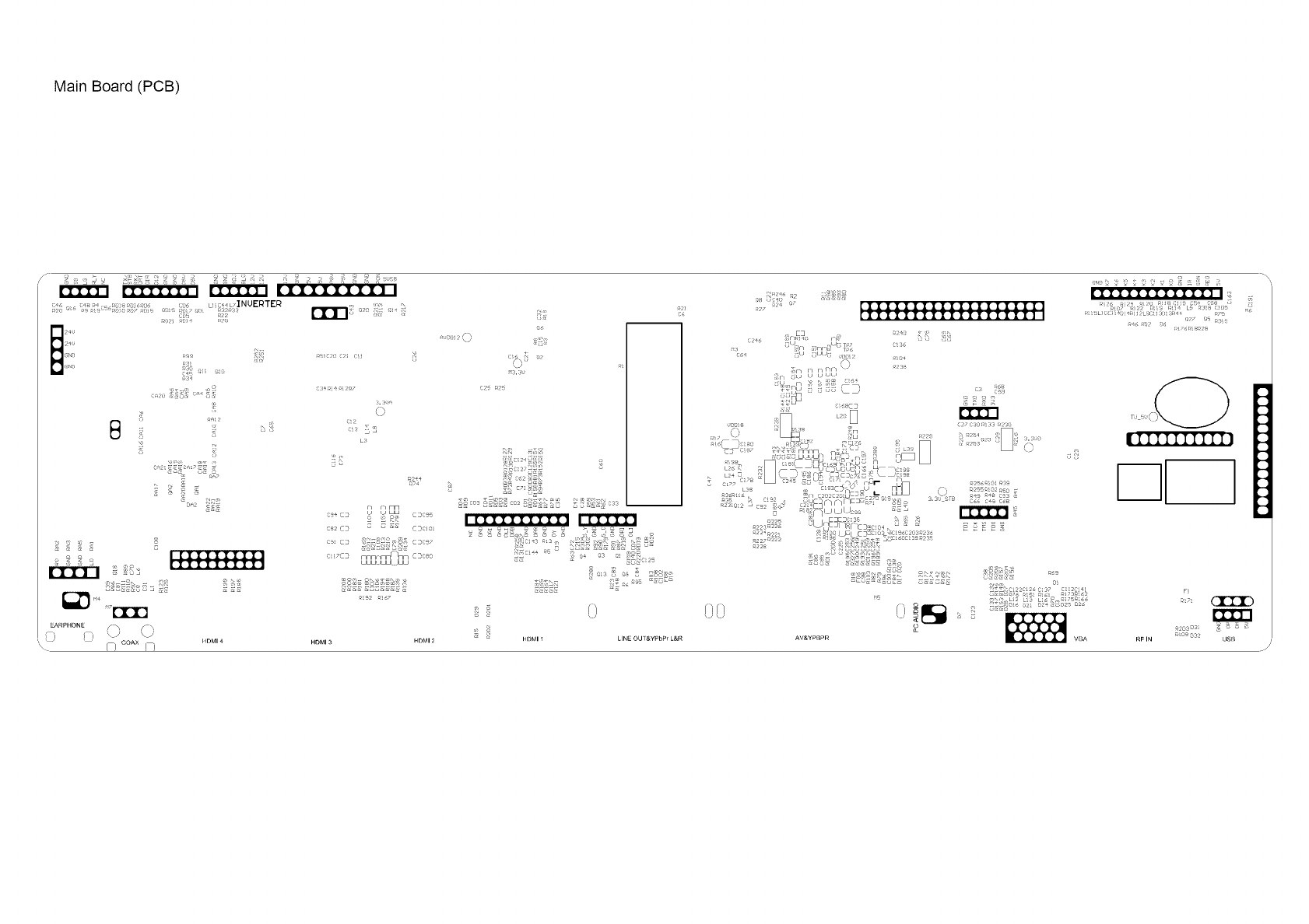
MainBoard(PCB)
s?
:.:us,
?; 0
L3
_2 _
o ; ; _ l [IIIIIIIIl
_ _ [IIIIIIIII]
aRPHONE !a (-)
HDMI 4
7_ coax f--i
_4
r/ [j mm
cs4 CD t _ wu
R _ _2 CDCD5
ce2 CD == CDC
c9_ CD 2SSAC_,q_ CDCe7
nnnr ¸ _nm
C_rCD uuuL _. Juu CDCeO
.........0 <5
0:u
<2 _2
77o_,7_7
:_>
I'I_ rl'l'?'l'?'l
2
zs <7 [IIIIIIIIIIIIIIIIIIIl
[IIIIIIIIIIIIIIIIII] I
E3 _2e
[J _LJ T 7 {; ;{_
s"fTrq [i fir / "T
{;5 jtJ ULJ{ 77j}7
,37n r / rq nrq \s i_s
Cf i {LJ U U ULI
'7<<7 ii :_i! _'<'+
_Tu u
_223 ff<225 _Oc]E3f Y_F CD_ o4< _ _ R _ _ R 5
a22_R2_. 5 £ ¢ L}7 _"r>S _0'_4;2_3_23 x
< 9 S S ? v ;
2 2e _zv <; b ;t_ {J
'L c "- L: ;n S_
s
IIIIIIIIIII!
F_
mr_
a2os os S _ _ _:
OSB
Main Board (PCB)
MainBoard(PCB)
CDc_7 L
o
MI_]N POKIER[- 11 I __
LUDS SSSSS_E_O _ ,, :_/I, , ,I JlI • J I
i,,. E3 o_ E3 rq _ mn _ n COC s:F_D ,N. _CD_ "1 CO _ E3E3E3 _ _E3CD _ CD
mr / u uu L "_ E2E2 E2 E2E3 E2 _ _E2 E2 _ E2
_ uu _ _ _ _ /x/_ S_ '_ S_ _s T PDP CONTROL
I/- _y _ _ ,.............
i•r/r/ rnr/ n _, EZ I
_; ......... fu/_ _ C2 _ un[un L E'-_%_,\_,%_ aCOMMUN]CnTIONi _m"
.JLJ _ /¢ I_ _,_ '/ \uo cs ",.\\X7 ,o N
u_l_ '2 ,c LjL: ) _s E _'/ _: ]I// --,, ,*, ! ,/ ' ....., L L _E3 • ". .... \t ......\
" uu_ _L_JUU C b.I
[J L E3 u ES _ _ E _] L_ _rfl y- -\
I./Lj f/nr_ _nr_r7 _ _ - '
3E2 I
__ _ _ _uuuut J uUUUbUu-- _UULUU-- --UU_
..... i!E_
c_= :_E_
.....* _0 B E
r_mnnn
o_o_ 0 r_r_.r_r_.O0.......O0
__ uut Juu_
.....
t so I I _ _ ?:_ EXT-HDMI * E*, _-- - _.- E,_
_£S_°n["_uuuOIl OununOununmot'r-]r_ rtic0c_00/_.° I \ _ . ,__,, m m m m
.... _ USPEAKERS U U U
C_on[]onL J L J u \\t>"
[_mOun ' JL at JL Ju _
tJ E_E_ _m FlrT_[_/'/1 421_F1rqrq \ .... /_nn "" rqrq n[/r-fq .......
noun O n *_ u ...... U ..... "UU U uu ou ........ ,,
I! :UT!T :l Ti; iTal I a:,,:i al I#:
I2 3¢5678_I0 11 12
i
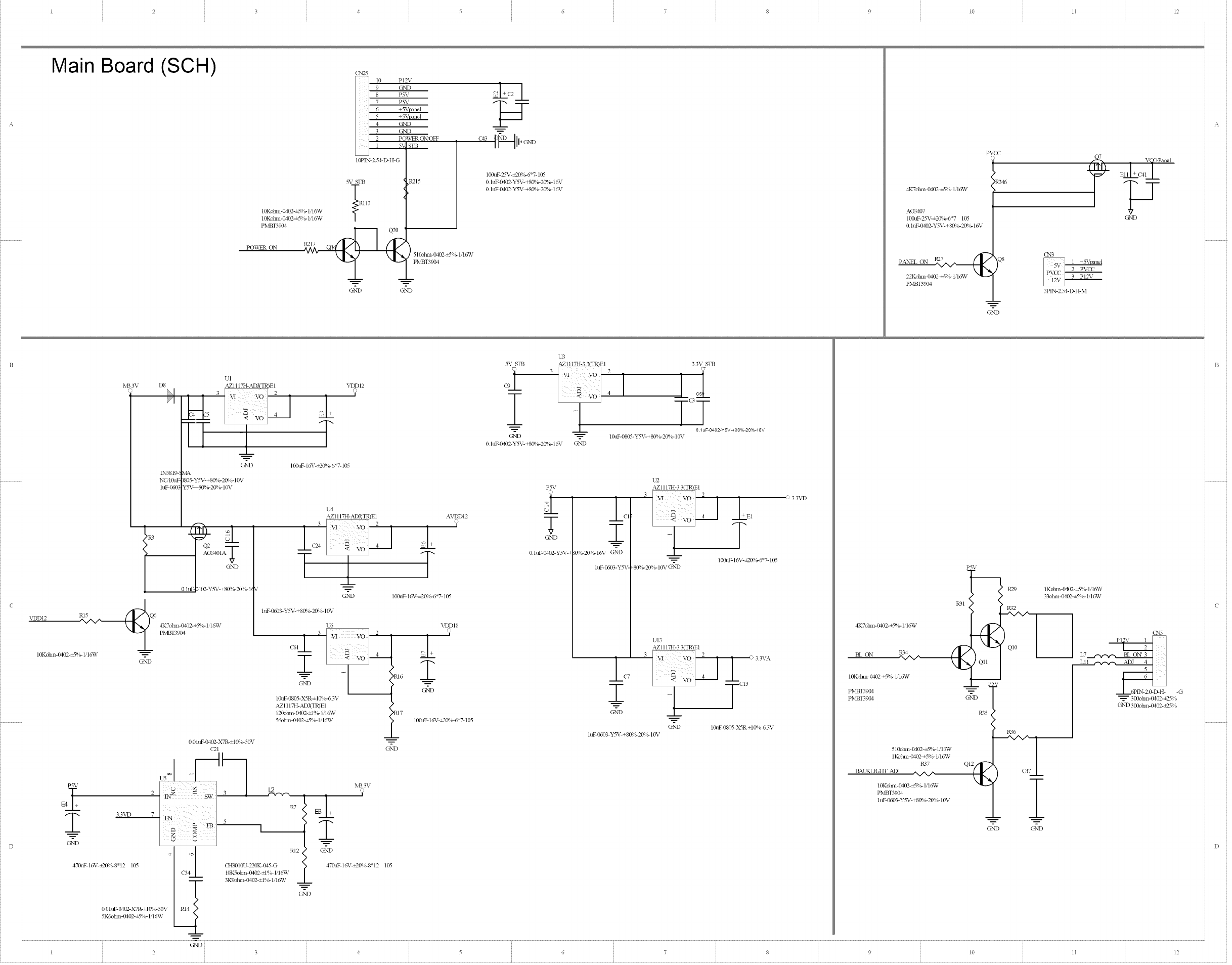
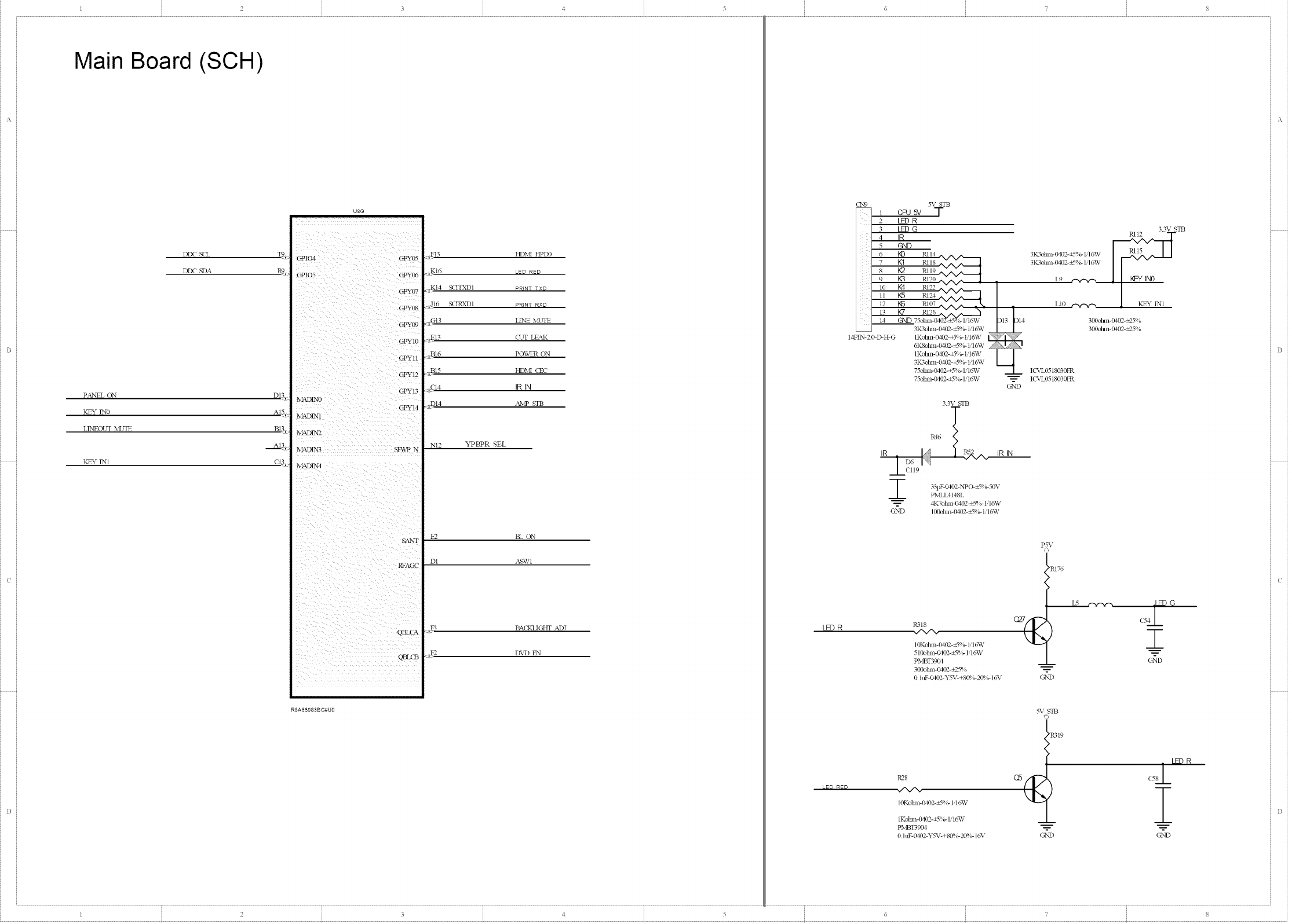
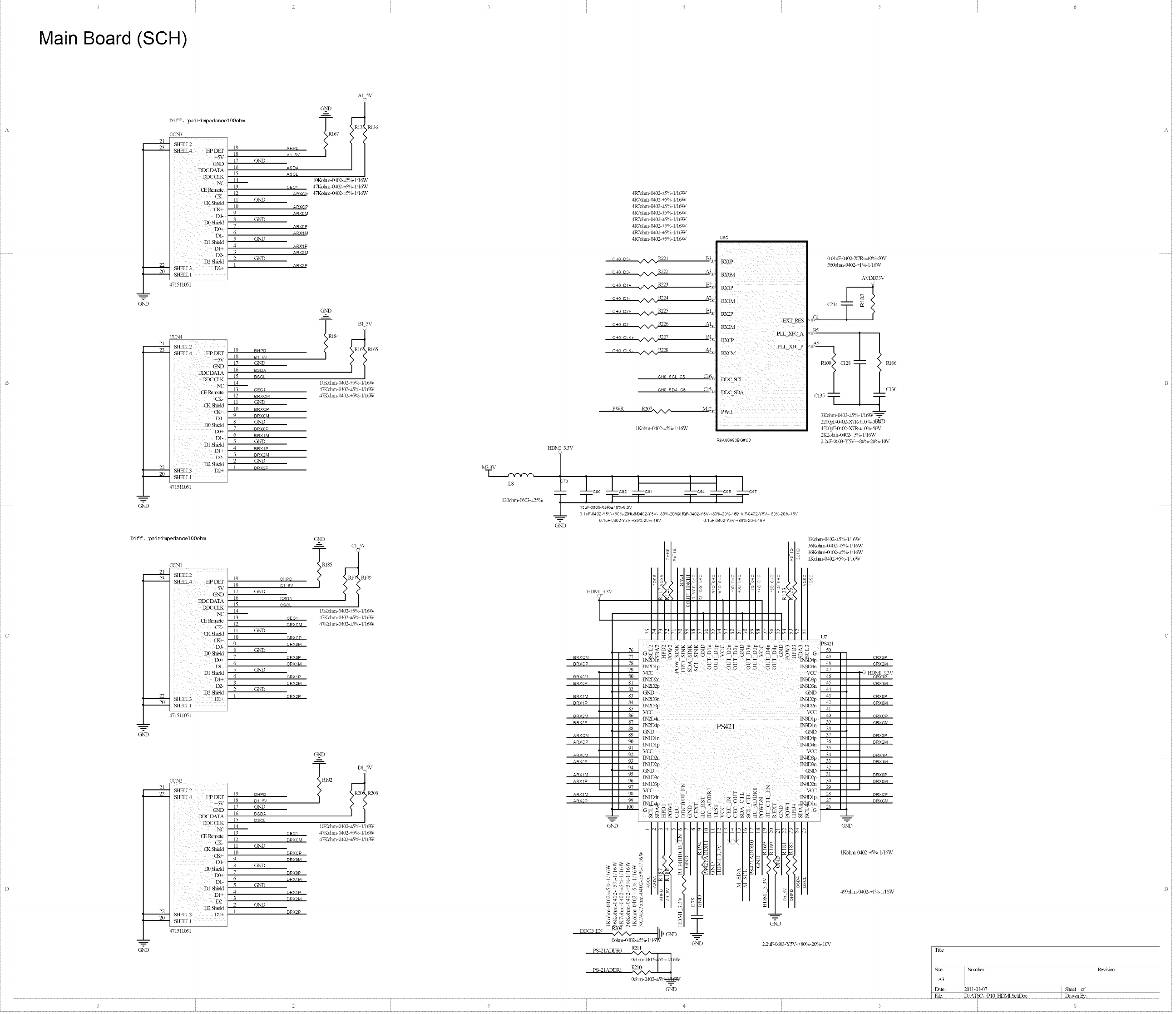
Main Board (SCH)
10Kohm-O@}2-_5%- Ho%V
10Kohm-{>D2-_5%- H6W
PMI3T3901
POWER ON
C_N25
IOPlN 2 5&I>tt G
_%_STB
47
GND
R215 100ttF-25T-+20%-6*7-105
0 htF- 0102-Y%_-+ 80%-20% - 16X,
0 htF-Oa02-Y%_-+ 80%-2_ 6- 16X,
510ohm-0d02-+_9_ ?,-1/I6TV
PMI3T39{2vl
GND
pv(u
4K7dun-('_}2-_S°>l,'l_V
AO34(_
100tkg-25V-_2{Y_6-6"7 105
0 htF-{MO2-YSX,C+80%- 20%- 16X,
PMBT3904
_R2'46
Q8
--___----
G%_D
VC Panel
GND
CN3
3 PI2V
3PIN-2 5&D-H-M
i
R,B3V D8 I
I
UI
AZI 117H-ADJ(TR)EI
E4
< VO_ ---_-j
[7 2
OND
IN5819-_ \_
NCq0ttF- )805-Y5T-+80%- 20%- 10V
htF-Wo03 Y5T-+80%-20%- 10V
Ip3o,
VDDI2 _Q6 PMI3T39014KT°tIln-('_)2-_-_%-Iq6W
10Kohm-( '_}2-_5%- I,'lo%V
GND
33VD
G%'D
*9
470ttF-16X,c+2(P,6-8 I_ 105
0 0htF-O_2-X7R-±I 0%- 50V
5K6ohm-0d02-_5%- 1,'lo%V
0 0htF-OI02-X7R-±I 0%- 50\,
(21
7 5
_%_ STB
VDDI2 O) L
,)
2' 2
OND
(HS0 IOU-220K-045-G
I0IC%lm>('_}2-±1%- 1/t6TV
3K%ban-0402-±t%- H6TV
100ttF-I6V-_2?ff_'b-6"7-105
U4
AZ 1117H-_ad)J(TR)E 1 A\'DD 12
2
I _vo_-_
r } T
G2N'D I00ttF- 16_,_27(P,b-6"7-105
htF-0603 -YSX,C+8(P, 6-20%- 10V
U6
C611 3 VO 2 ,
4
< VO /
_RI6
I0ttF-0805-X5R-±I 0%- 6 3V
AZI 117H-&d)J(TR)E 1
120ot]m-0402-=t %- 1/1o%V
56ohm-0402-=5%- 1/1o%V
L2
,T
RI 2 G2N'D
GND
i
T
GND
VDDI8
N_.3\
,?
*9
470t_16V-+20%-8 '1- 105
7 100tiF-16V-_20%- 6"7- 105
&T,'D
U3
AZ 1117H-3 3(TR)Et
] _ |
1
0 htF-O_2-y%_-+8@ 6-2(P,6-16X, GND
33V STB
TT
0.1uF4}g02-YSV480%-20%-16V
l 0ttF-0805-Y52'C+ 80%-20%- 10\'
P5V
i
T
G%_D
0 htF-I£D2-YSV-q
C1
D
0%-20%- 16X, G2N'D
htF-0603-Y52,_
U2
AZI 117H-3 3(TR)E1
E
<vo_--_ _1:-=
1 T
I00ttF- 16X,_+2(P4,-6*7-105
_8_ 6-20%- 10\, G%'D
UI3
AZI 117H-3 3(TR)E1
3 VI i f;' 3 3\%
lc. E 4
: 1 TCI3
G2N'D 10ttF-0805-X5R-±I 0°_6 3V
htF-Wo03-Y5T-+ 80%-20%- 10V
4K7dun-('_}2-_S°>i,'l_V
BL ON R34
10Kotm_-{MO2-+_Sq>lilo%V
PMI3T39{M
PMI3T39{2vl
510ohm-B102-_5%- 1/16W
1Kolm_-0102-+-5%- I q6TV
R;7
BA(KLI GHT &d)J W
l0Koban-0402-_5%- H 6TV
PMBT3904
htF-0603-Y52,c+ 80%-20%- 10\,
P5V
R31
R29 IKol?an-0102-_5%- Iit6TV
33d_m-0402-_5%- Ho%V
R32
R35
QI2//_
--_----
G%_D
R36
]
G%_D
CN5
_1_
300oban-0402-+25%
GND 300oban-0402-+25%
GND
I2 3¢5(5 7 8 9 I0 11 12
? 3 ! ,_ . .. o.... ,. .............
.......... _ .. .J ..................
Main Board (SCH)
DDC S(E T_
DID(" SDA Rg_
p.&NEL ON DQ,:
KEY INO A[5.__
LINEOLT NL'TE B13x
KEY INI
U8G
:GPY08
GPY1C
GPY!I
GPY12
MADIN1
MADIN3 : SFWPN
_ADIN4
F2 BL ON
D I ASEV[
BA(KLIGHT ._d)J
DVD EN
RSA66983B G#U0
LEDR
CN9
14PIN-2 0-D-H-G
.%- STB
, _SV T
2LE) R
3LB3G
4 IR
5GND
6 _ RII4
7K1 RII8
8 }<2 RII9
9 K3 RI20
I0 Nd R122
II }<5 R124
12 K6 RI07 ^'^ ^ _"_
%/X/" :
13 I(7 R126
14 GND 75ohm-O40Z-:k_/_ 1q6W
3IC_ohm-(/vRP_-+5%-1/1o%V
1Kohul-0402-+sq 1,-1/16W
6K8ohm- (/vRP_-+5%-1/1o%V
tKohm-0402-+5%- Ii16W
3IC;otm>(M02-+5%- 1/16W
75olnn-lM02-_5%- Ii16W
75olnn-lM02-_5%- Ii16W
33\ STB
_.Lc119
3IC3dm>{M02-+5%- I,'Io%V
3K3dnn-{g02-+5%- [l_V
33pF-0dO2-NPO-i5%-50V
PMLIAI48L
4K7ot_n-0402-_5%- I,'I_V
G2XD 100o17an-0402-+5%-I, I6W
P,318
./X/X.
10Kotm>OaO2-+5%- 1 16W
510ohul-0d02-_5%- lq6W
PMBT39{_
300ohul-0d02-+.25%
0 htF-0dO2-Y527-+ 80%- 20%- 1o%-
R28
./X/X.
10Kotm>0_2-+5'V_ Ii16W
IKolnn-(MO2-+5%- Ii16W
PMBT3904
0 htF-0_2-Y5%--+80_ 6-20° _-1o%-
L9
LI0 ¢.-'.1-".1%
i %
I(%'L0518030FR
I(VL0518030FR
¢_'D
IRIN
3.3V STB
300ohm-0d02-_25%
300ohm-_02-_25%
PSV
o
_Rt76
GND
L5
mm
GND
S_STB
'PSI9
GIx]D GND
...... ........ - t5678
1 2 3¢5 G
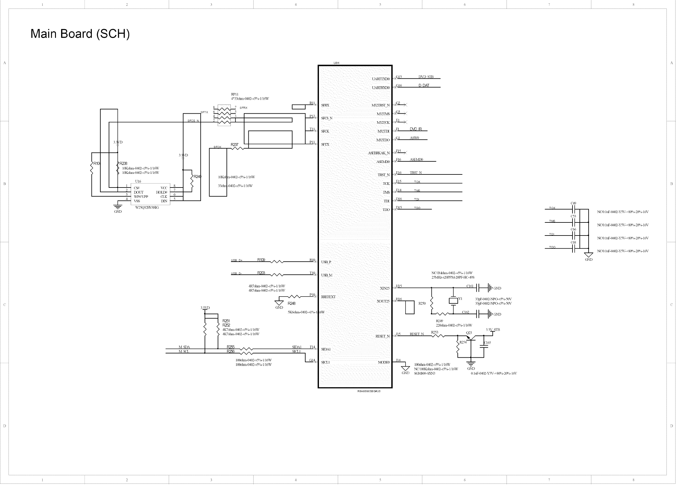
Main Board (SCH)
13
35
R1 R278
I I _ 10Kolm>O_2-_5%-H6W
] ] 2B DOI_ HOLD_
V_'VPP <LK
VSS DIN
W25Q32BVSSIG
GND
-- SFTX
P
2R2,*
RPll
4*33dm>l>D2-_5%- H6W
SFRX PI_,.
10Ko n-0402-_5%- H6W
33d_t -0402-_5%- H6W
uss D+ R109 _ RI0_
usB D- _ _ TI0_
M SDA
M S(-L
33\_'D
R252
4K7olm>0402-+5%- H6W
4K7olml-0402-+5%- H6W
R255 ./N/N.
R256 ./N/N.
4R7ohm-lMO2-_g%- 1/16¥V
4R7ohm-lM02-_5%- 1/16¥V
P_L
G%'D
5K6olm>O_2-±l%- ]
100olm1-0402-+5%- UtO%V
100oban-(,_P_-_5%- 1' 16W
NDAI FI4,¢
N(LI
U8H
ASEBRKAK N
Ab_'b.,IDO
L_V
SICLI MODEO
iiiiiiiiiiiiiii iiii
.,GI5 I)%7)STB
_£316 D DAT
:,:FI D'vD IR
_GI AS%VO
.FI6 ASEMD0
:_E16 TI{STN
.EH TV*
__.D16 T_I
<_DI5 TOO
iN<','INb!?an-(,v!O2-+5%-t,'16W
25MHz-+20PPM-20PF-HC- 49S
.,HI_6[_YI 33pF-0dO2-NPO-_5%- 50\,
"_ R250 33pF-O402-NPO-+5 %-50\,
R249
220olnn- 0_2-=5%- 1/16W
33V STB
R253 O_ "T"Q23
_315 RESET N ^^ _-- _l
J14
100ohm-(/_P_-_%- H6W
NCq 00Kolml- 0102-+5%- 1,1o%V G_N'D
G2N'D _MSIN)- S)LN3 0 htF- 0_2-Y5V-+ 80%-20%- 16V
C49
T_&q
iT-I-
7
C_D
NC'O htF-IM02-Y5V-+80%- 20%- 16V
NC'O htF-IM02-Y5V-+80%- 20%- 16V
NC'O htF-IM02-Y5V-+80%- 20%- 16V
NC'O htF-IM02-Y5V-+80%- 20%- 16V
,%
1 2 3 ¢ 5 6 8
I2 3 4 5 6 8
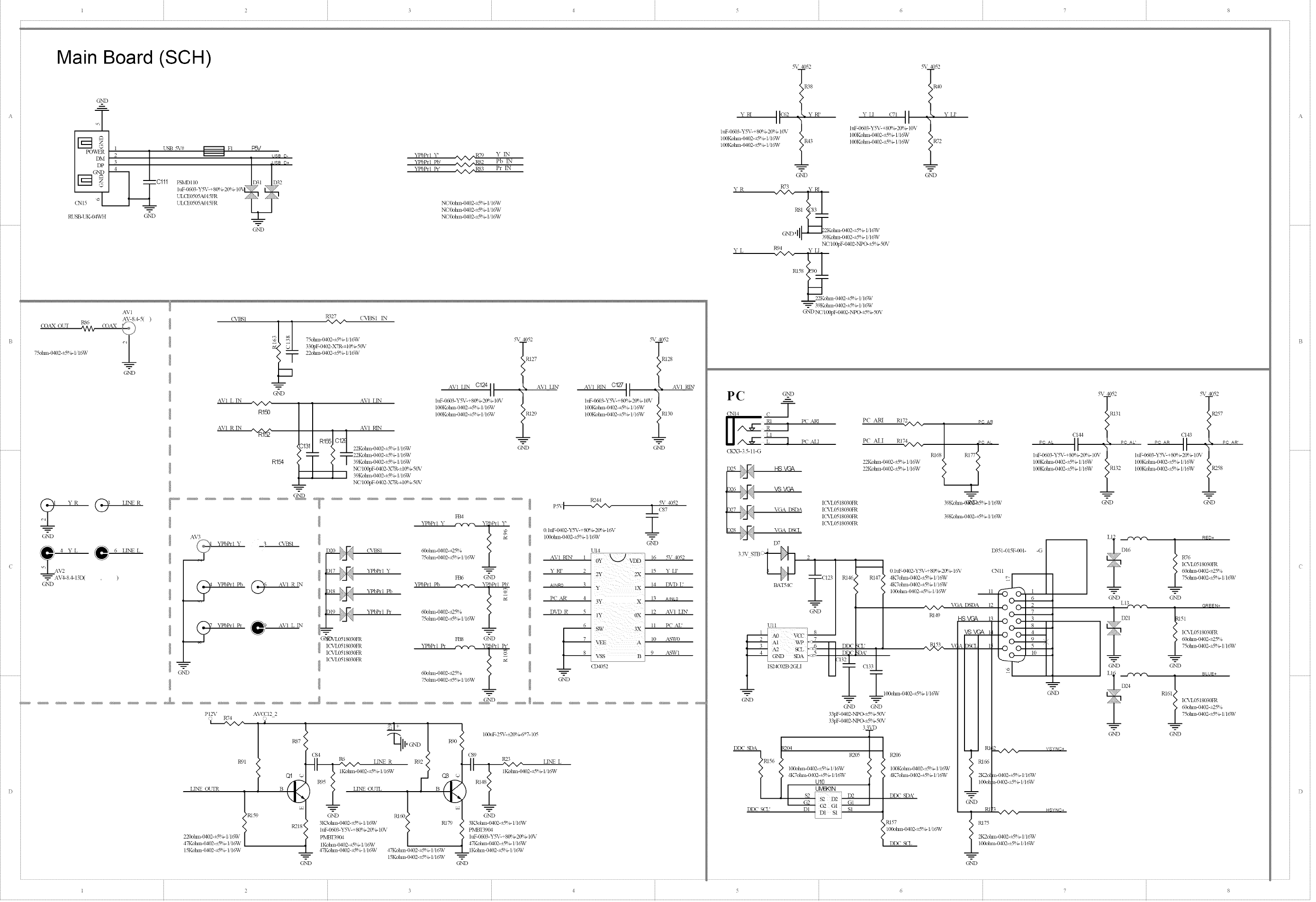
Main Board (SCH)
G%_D
5_ 4052
TRY8
>
_-Pa iic_2 .L YRI,
hff'-0_3 -Y5V-+ 80%-20_ g 10V
100Kotun-O4(E-+5%- H 6W _R43
100Kohm-( '_)2-+5%- l,16_V
CNI5
RUSB-UK-04WH
USB 5V# _ FI l[:SV o+Ii
_ #+
, . htF-0603-Y5V-+ 80%-2(Y%-10\ _2
0111 PSi,D110 D31
UL(E0505A015FR /l_l S I_'_
-- ULCE0505A015FR I I
G_'D
G_'D
YPbPH "f _N/Np R79 Y
YPbtM Pb' R82 Pb
'N/NP . Pr IN
YPbtM th" _/N_ R8__
NC'Lk_hm-( '_)2-_5%- 1/16¥V
NC'Lk_hm-( '_)2-_5%- 1/16¥V
NC'Dohm-( '_)2-_5%- 1/16_V
AV 1
75olnn-0__-+5%- H6W i
GND
Y R @ LINE R
G%'D
1A\'.
__'_- AV4-84-13IX )
G%'D
CVBSI Rg27 (_v_S 1
'N/N/'
_ 75otun-O:D2-_5%- H 6W
330pF-0402-XYR-±l 0%-50V
22ohm-Od02-_5%- 1/16_V
---1
@ND
AVI L IN
R150
A\4 LIN C124t1
htF-0_3-Y5X--+80%-20%- 10\,
100Kotml-0402-_5%-1,16W
100Kohnl-lM02-_5%- 1,16_V
_%_4052
t127
, AVI LIN
AVl
RI_ C1
71 22Kolnn-O_2-+5%- 1/16W
,--r'- _ "-r -22K°lnn-0402-+-_%-liI6%V
R154 | <_ /39Kolnn-O_2-+5%- M6W
NCq 00pF-O_2-XTR-±I (£ b-50V
1 1 I 39Kolnn-O_2-+5%- H6W
NCq 00pF-O_2-XTR-±I (£ b-50V
G%33
.................. T ............................
A\,3
YPbtM Y 3 CVBSI
CJ_D
A\I R IN
A\I L IN
G%R2&%0518030FR
ICS,%0518030FR
ICS,%0518030FR
ICS,%0518030FR
CVI3St
YPbthl Y
YPbth'l Pb
YPbPr 1 th
YPbtM Pb @
FEN
YPbPH Y
60olnn-0402-+25% /
75olnn-0402-+5% l q6%V .__L
FB6 G_'D
YPbth'[ Pb _lPb'
60olnn-0402-_25% /
75olnn-0402-+5_ l qO,V ---L
FB8 G_'D
YPbPH P*
60olnn-0402-_25% /
75olnn-0402-+5_ t qO,V ---L
_._ YPbPr[ I_ O---
AV1HN'
_R129
--_=.--
OND
5_ 4052
',128
A\,[ RIN C127 I I
h_-0(_3-YSX--+80%-20%- I0V
100Ko{m_-0d02-_5%-1 I0%V
100Ko{_n-0d02-_5%-I,16W >RI30
GND
AVI RIN"
R2'44
P_%__
0. htF-O_2-Sq%'-+ 80%-2@ o-16_,
t00olun-0402-_5%- H6W
UI4
AV1 RIN' 1
Y RI' 2
AINR0 3 y lX
PC AR2 4
DVD P_ 5
6
_7- sw 3x
2-%:::2....°
OND
m
G%'D
16 .%- 4092
15 Y LI'
14 D\Z) U
13 AtNL0
12 AVI LI_
11 PC AL'
10 ASW0
9 AS_V1
PI2\ A\<PI22
R74
R91
R87'
Q1
± I
II'c_
C'P4 R6 LE','E R R92 < C89 R23 LINE L
1Kolnn-0dO2-_5%- M6W 1Kolm>O_2-i5%- M6W
LINE OUTR
220olm> 0_2-+5%- 1,'t6W
47Kotun-Od02-_5%- H6W
15Kohm-Od02-_5%- 1,16_V
_R159
R218'
G%'D
YH II
htF-0603-Y5V- +80%-20%- I0\,
GND
YR
YL
100Kolnn-(MO2-+5%- 1/I6W
100Kolnn-O_2-+5%- 1/I6W
PC
CNI4
R73 YRI
RS,,, _, _ _Kotun-Od02-_5%- 1,'16W
..... II 39Kohm-Od02-_5%- 1,16_V
R94 NC' I(_F-OdO2-NPO-+5%- 50V
YLI
..J.. P2Kot_n-( '_)2- +50_-l,l 6_•
39Kotun-( '_)2-+5%- 1,16W
G'N DNCq 001)F-(,_)2-iXPO-+5%- 50\,
_%_4052
TRI3I
>
/
c144
L PC AL'
po,L i.I .
II
htF-0603-Y5X--+80%-20%-10\,
100Kolnn-0402-_5%- M 6W
I00Kolnn-0402-_Sqg 1/I6W _R132
GND
5_ 4052
t40
, Y LI'
_R72
G%'D
_%_4052
K257
C14311 L
.... il " P?AR'
I I
htF-0603-Y5V- +80%-20%- I0\,
100Kolnn-0402-_5%- 1/16W
100Kolnn-0402-_5%- 1/16W R258
GND
......|., DI6 R76
_,) KNI0518030!:R
60otun-( '_}2-_25%
.i75d_m-( '_}2-_5% -1/16W
O'ND G%'D
L 13_-_-v.-_ -GREEN+
]I)-91 _5i
IC%'L0518030FR
60otun-O4(P_-_25%
.__L75otun-( '_)2-_5%- 1,16W
O'ND G%'D
LII _ i BLUE+
RI61 IC%'L0518030FR
60otun-( '_}2-_25%
.__L75ohm-( '_)2-_5%- 1/16_V
O'ND G%'D
_PC ALI PC ALI RI7_,V_ _ _ &_
CKX3-35- ii -G Pd68
P2Kotun-O4(E-+5%- 1,16W
HS VC4k P2Kot_n-( '_)2-+5%- 1,16W
VSVC_
I(_%0518030FR 39Kolnn-0_k5%- Ii16W
VGA DSDA ICS,%0518030FR
ICS%0518030FR 39Kolm_-0_2-i5%- lq6W
I€S%0518030FR
VGA DS(L
D7
33V STBC_)_ L] 2 D35I-OIqF-001- -G
H
FI TCI23 R1'46_" R! Jx/ 4K7olm]-_2-_5%-li15W :1
aaTS_' /??4K7°hm-_2-_g%-H6XJ
/>> 100otun-O_E-_5%-l,16W _ m'_ I
_.L
-_ l/ ,N/N/_ VGADSDA 121o°;12
// ,sv 13!;Oo1:
, ltlo
_ _AL> I/o_cba_ / / I /1" c v,I _o
t H3tcr //1/w___
__z___z_,_o,_,,o402.._.,_v/ / i / o_
//1/
//1/
4_-_4 4</ ',_/
/ 1 s2_ _: / _ *_._ / -- /
DDC S(T& DI _ SI / i _[3 _ NSYNC+
Pd57 Pd75
100otun-0402-_5%- H6W
2K2olm>(H02-_5%- Iil_V
DDC S(TL 100olnn-0_2-_5%- H 6_V
-.__--
[2345678
J i 2 • [ • • • • • L • • • •
••••J•••
C •
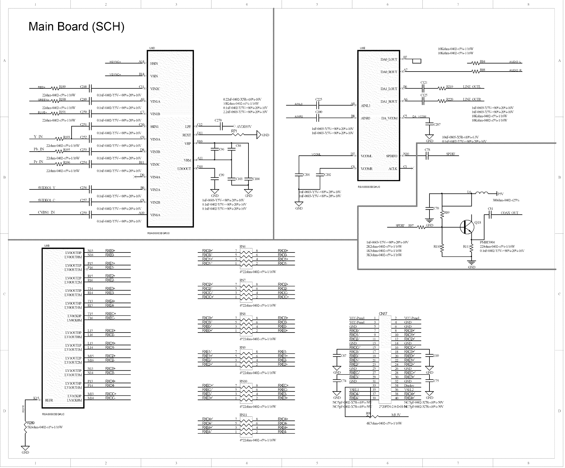
Main Board (SCH)
HSYNO+ AI_
WyNc+ B_,:
f_7_+ _NVI_ s9 (2,48_ I c!1,£
22ohm- fM02-_5%- 1/16VV 0 htF'LkR]2-Y%2+S0%'-2(P_ _ 16¥
...........9_._1_Rt 90 (24911 ,'9_o
22ohm-0J,02-_5%- 1/16T¥ 0 htF, Oa02-Y% -+8_ _2d_ ;- 16V
BLUE* a_V_RI91 (250 I I C7:
22ohm-0102-_5%- 1/16W 0 luF_t_2_y%'-+SCe _-20q;_1o%"
Y_ .4Agm93 c:P-I_
22ct_n-@,0>_5%- 1,_[6W 0 IuF-(HO2-Y%_-+80%-2ff_ b- 16%;8__
PblN .dv_R[95 (253 I_
22olml-6102-_5%- 1/10T¥ 0 htF-0J'O2"Y%'-+80%-2ff)_ _ 16Y
PrIN _]_ RI96 (254 It B11
22obm-0_2-_5%- lq6W 0 lmF-0402-Y%'-+80%-21_ m16\"
>+...--_,-
SVIDEOI Y t_ E__
0 htF-OdO2-Y%_-+80%-2ff%- 1o%"
S\qDEOI C It (_'
0 htF-O:RY2-Y%_'+80%'2_g 1o%"
('_]3SI _N (259 t t ,,10
0 htF-0aO2-Y% _-+80%-2(B_ 1627
UBB
LVOOUTOP
LVOOUTOM
LVOOUT1P
LVOOUT1M
i
LVOOUr2P
LVLKKH'3M
L'VOOITF4P
LVOCKON
LV1OUTIP
LVIOUT1M
L'V1OL_2P
LV1OUT3P
LVtOUT3M
LV1OUT4P
LV!OUT4M
LVI(NOP
[.__A_5 e,m{ m'KX0M
_ / _2_9 RBA66983B G#U0
5Kdohm-0402-±t%- lilo%V
Nt5
Nt6
Pl5 PO_t+
216 po_t-
m5 R,TS+
m6 R_-
TI4
Pd4
TI3 R,XE4+
m3 RXE-4-
TI5 R)_-C+
TI6
L15 RXC0+
LI6 ]:_XC0-
LI3 RXOI+
LI4 RXO1- _
MI5 RXC@+
MI6 RXaS-
NI3 RX(TB+
NI4 RX(28-
PI3 RKO4+
PI4 RXO4-
Mr3 RXOC+
MI4 RXOO-
U8D
]
TTN2C
i i Yll ii ii_
<:;Z i_iii _ii i i ii
\bIN1 LPF
VLN3B
0.22uF- 0402-X5R-: t 0%- 10V
t0Kot_n-0 D2-_-1%- IiI6W
0 hlF.( __-y5¥-+80'_ _209 _ 10%7
2 2uF-0603-YS¥-_Bt _ _-20%- 10\7
(270
<__ _.-.--_ } AVDD33,
:_.DIl ' ' -_A-@ GND
_D_0
>----_E99 _C[04
GND LiND
h__0603-YSV-+ 8_ ;- 2£_hMOV
0 hlF-%1,02-Y%2+8& ,r209 b- 10%"
0 h_F-O_O2-Y%'-+S0q _21_ 6-1o%,-
_A
RBA66983BG#U0
(225
A'_u° It ,,.8
i uF_0603_Y%2+ 8@ 3- 20%- 10N7
i uF_0603.Y%7-+ 8_ o- 20%,- 10\ r
y cOML
GND
RN6
P.X(I_+' 7 _ s RXO0+
RXC0-' 5 6 RXOg
RXOI4 a 4 RXOI+
RXOI-' ] 2RXO1-
4*22olm_-o4o2-<_%-l '1o%V
U8E
RN7
RXO2+' 7 _ s RXU2+
RXO2-' 5 6 RXO2-
RXOG-' 3 4 RXC_-
RXOC+' 1 2 RXOG+
4*22dnn-{M02-<_%-_ 16W
RN8
P,XU3+' 7 _ s RXO3_
RXO3-' 5 [ 6 RXO3-
Rm>' i 2
4*22olm_-O:D2-+Sgg Iq 6W
RN9
POqE1-' 7 _ 8 PO_I-
P0_I+' 5 6 P,_Et+
P0_2-' 4 POUc2-
R>ES+' ] 2
4.Z_9o_m>0402-+5%- [/16W
RN_0
POd-C+' 7 _ 8 R_-C+ _
RXEC-' 5 6 R_-C- _
P,_E3-' 3 4 P0_3-
R_S+' ]2RXE3+
4.22olm>( '_2-+5%- l'1o%V
RNII
RXO4+' 7 _ 8 RXC4+
P,XOg' 5 6 RXO4-
RXE4+' 3 4 RXE4+
RV-*' :, 2 av-¢
4*22d_an-0402-<SB _ UL6W
MNR3 DA VCOM
VC'ONL SPDIFO
V(_ON_R ACLK
i
IIlll
RBABBBB$BG#U0
_A7
[0Ko[m_-O_2-£5%- 1,'16T¥
[0Kolm_-O_2-_5%- H6W
CI21
C125
£5
,_/w_rR_, AAUDIO L
_/_RS'8 AUDIO P_
LD,,'E OLTL ,
CN17
_-C(sPanel I .
VCC-Pa::d 3 .
GN_D 5.
RXO0-' 7.
RXO%' 9.
RXO2-' H.
GND 13.
RXOG-' _5
S, RXCB-' 17
67 P0_c:0-' 19
PO_I-' 21
D0_2 P 23
GND 25
C£ND P0<EC-' 27
LR)__3-' 29
C'4 GND _
RXO4-' I 37
GND |P0_--d-' /39
t _mLv,
LE',,'E oUTR .
htF_0603_Y5_,c+ 80%-20%- 10V
htF_0603_Y)_7-+ 80%-20%- IOV
IOKoDan-O402-£: B_ H 6W
Dh \/con 10Kolnn-0402-£S%- 1'16W
287 10ttF-0805-X _R-_I_ _-6 3\r
GND '?- _ :-+ "_ :
_8
(7O
2P,S9
SPDIF R97 .aTV_ciN9
RII0
VCC-Panel
GND
GND
RX(X}+'
RXOI+'
RXO2+'
GND
RXOC+'
P,_EI+'
G_sD
2B RYEC+' _7C7
30 R,W_3+' .
32 GT,!D . 5
34 DBplav .
36 VSEL2 .
38 RXO4+' .
40 RXE4+' .GND
NC,5pF-0402-X7R-±I 0%-50\:
2*20PIN-2 0-D-H-NC'5pF-O402-X 7R-±10%-50\7
I',,I33\:
htF-0603-Y5\--+g0_ _-2tY__-[0\:
2K2olm>0402-+5q _-1/:6%1:
tIC%[ nn-0402-_Sq i,- 1/:o%¥
3K3obm-(,vl,0_+_@/_1/i o%¥
4K7olnn-0_2-+5%- 1.16W
301kt_an-0402-_2-5%,
RIll'
CBI
pMBI'3904
220ohn]-{MO2-_Sq> 1/1o_¥
> 0 hl_0402-YSV-+B0'_ _-209_-_6U
%
123¢ _ 5 6
Main Board (SCH)
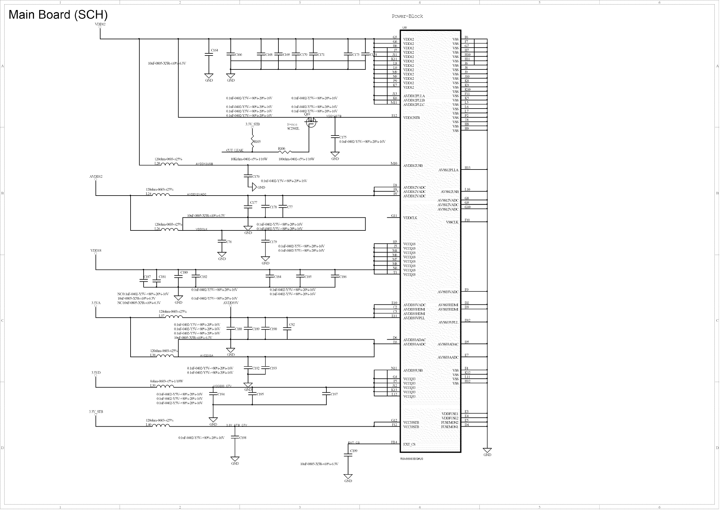
VDDI2
[
10uF-0805-Xq_-±i0q
120olm>0603-_25%
A\rDDI2
O
I120olm>0603-+25%
L24
Power-Block
120olm>0603-+25%
L26
ST
33VA
O
I
NOD hff'-0402-Y-%_-+ 80%-2(P,6- 16_,
10tff-0805-X5R-±t 0%-6 3V _7
NC' 10tLF-0805-X5R-±t_ 6-6 3V ND
33\T)
O
I
63\,
120otml-0603-_25%
33\ STB
L37 _¢-'y--,/%
L1 1111 ]]
.... TC, TC, TC,7OTC, ,----C173--[C14
v v
OND G_'D
AV_12W_
0 htF-0_2-Y5_,c+ 8(Bb-20%- 16V 0 htF-0402-Y5_,c+ 8(B b-20%- 1o%"
0 htF-0402-YS_,C+ 80%-20%- 16%"
0 htF-0402-YS_,C+ 80%-20%- 16%"
0 h_ 0_2-Y5_,_+ 8(Bb-20%- 16V
33\ STB
(LT LEa]4 i RI05
0 htF-0402-Y5V-+80q 6-20° _- 1o%"
0 htF-0402-Y5V-+80_ 6-20° _- to%"
QI9 VDDI: STB
N-rots -_
S(2302L
RI06
"N/N/'--
10Kolml-O_2-+5%- H 6W 100olm1-0_2-+5%- H6W O'ND
120olm>0603-+25%
L?8
---2ZC176
0 htF-0402-Y5V-+g0q 6-20° _- 1o%"
AV_l_YS_ i "177 1 1
10uF-0805-X5R-±I@6-6 3V --- T CI78 T C77
0 htF-(_2-Y5V-+80q 6-20° _-1o%"
----('76 TCI79 0 htF-0402-Y%_-+80%-20$g16_ ,
470 htF- 0402-Y%_-+ 80%-2(B g 16_,
X7
G%'D
OND
0olm>0603-+5%- t,'10W
k_9
120olm>0603-+25%
_1_ _k i
0 htF-O_2-Y5V-+ 80qg20%- 16V 0 htF-0dO2-Y%,C+ 80%-20qg 16X,
0 htF-IMO2-Y%,c+ 80%-2@ g 16X,
0 htF-O_2-Y5V-+ 8_ 6-20%- 16V
AVDD33\
O
hlF-0dO2-Y5_,c+ 80%- 20%- 16V -- -- 1 1 1 v)2
htF-0dO2-Y5_,c+ 80%- 20%- 16V -- --C188 C189 CI90
hlF-IMO2-Y5X'c+80%- 20%- 16X' T T T
_.tF-0805-Xq_-±t 0%-6 3\,
X7
_L
CI86
}
1
0 htF- 0_2-Y%'- + 80%-20%- 16_,
0 htF- 0_2-Y%< + 8(P,b-2(Bb-16_,
-- _._9_ @7Y
V-+ 80%-20%- 16X, -- --C194
%'-+8086-2086-1o%,
V-+8(B b-2(B b- 16_,
11
CI93
-- --C195 i
CI97
V
O]ND 8,8V2¢7V
0 luF-O402-Y%_-+80%-2@ &-16_, _CI98
END
EXT CS
10uF-0805-Xq_-±t 0%-6 3\, ;
G%'D
G6
H6
J7
Jll
Kll
L8
15)
IvD
N9
P9
K7
Jl3
K6
Nil I
E12
NIl0
E8
GII
H5
J5
Nil
M0
NF
M8
N6
TI
El0
(2
(3
Ell
I96
E6
Nll
G4
P5
J12
K13
L12
vuu:z v,'x> F6
F7
"VI)D12 V,_S
VDD12 V,_S G7
H7
HI0
VDD12 V,_S
VDD12 V,_S HII
J6
VDD12 V,_S J8
VDD12 V,_S Jl0
K8
VDD12 V,_S K9
V_ KI0
A_D1 _Ii_A VSS FI 1
AVDD12PLLB \'_ IL<;
A'v_D12PLLC V,_S L5
L6
L7
V,_S P2
T8
V,_S H8
H9
A'v_D12USB HI3
AV,_S12PLLA
A'v_D12\L4DC
A_D12'£&IX" AVSSI2USB L10
A'v_D12'vL4IX" AVSS!2VADC G8
G9
AVS$1Tv'ADC
AVSS!2VAIX" GI0
FI0
V(IX218
VOOQ18
va:r0_s
E9
A_D33YLAIX" AVSq33HDI_R D2
A_D33HDMI AVSS33HDMI D3
A'v_D33HDMI
A'v_D33_v'PLL DI2
D5
A\rDD33AADC AVSS33ADAC
AVSS33AAIX2 E7
A\_D33USB V,_S F4
V_ KI2
Lll
HI2
V(XgQ33 v'SS
VOOQ33
V(XgQ33
VCILQ33
E3
VDDFUSE l
G12 VDDFUSE2 E5E4
FI2 D4
H14
x xxxxxxxx
_7
OND
4
,123:6
1 2 345 6 8
84pad
Main Board (SCH)
R141
100ohm_402@1%-1/16W
R143
100ohmS402@1%-1/16W
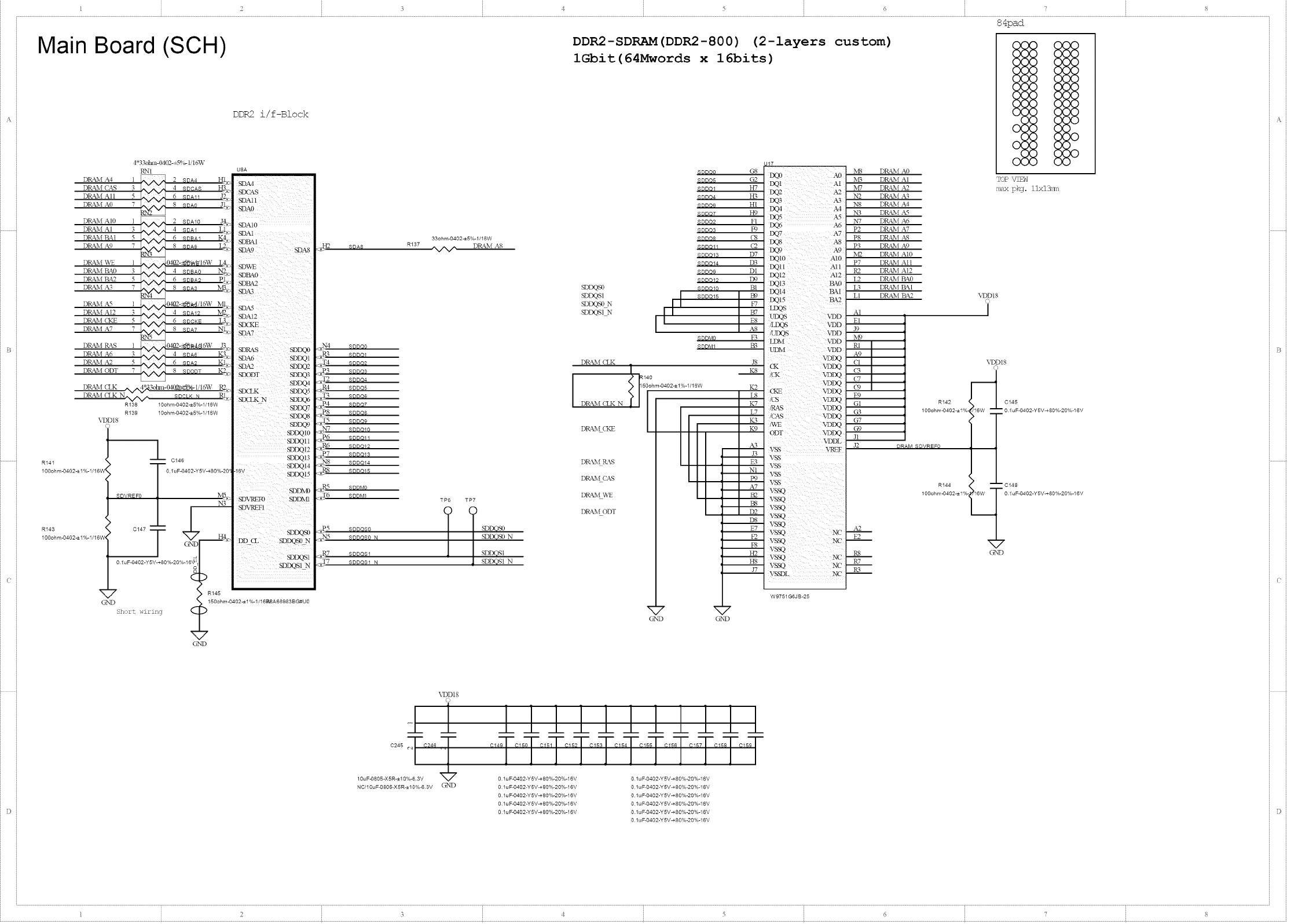
DRa£_f .%4
DRa£_f CAS
DRa£_f AI 1
DR&M A0
DR&M AI0
DRkM AI
DRAb{ BA1
DRAM A9
DRAM WE
DR&M BA0
DR&M BA2
DRAM AB
DRAM A_
DR&M A12
DR¢M <KE
DRAM A7
DRkM Ra_S
DRkM A6
DRkM
DRkM
DRkM
DRkM
4*33otm1-0402-_5%- IildW
RN1
l _ 2 .... HI,
3W 4 SOCA8 H3_
5 W 6 SDAll .12_
7 _ 8 SOAO J_
l'_,JN/ 2SDA10 JQ.
3_._._ 4 SOAI LI_.
5 %/NJ' 6SOSAI K4_
3 @ 4SDBAO ]'_2
5 @ 6 SOSA2 PJ-s
7 _ 8SDA3 N_.
l %/,v _ {2_2-_'8_/16TV MI,
3^._,,,_ 4 80A12 N[_
5 w 6 SOCKE _4_
7 _ 8SDA7 NI:, S
1 W 0402-_,8_Ist6W J3F_
3W 4 SOA5 1<;3,_
,62 5 W 6 SDA2 Kly;
ODT 7 @ 8 SDODT K2k
(LK @3otml-O4/_?Bdk%-lii6W R%
(LK NW SDCLK N P_K
R138 10ohm4}402-=5%-1/16W
R139 10ohm4}402-=5%-1/16W
\DD18
-- -- C146
0.1uF-0402-Y5V-+80%-20
SDVREFO
1-
_ _ /
c147
7
OISD
Sh:)rt wiring
DDR2 i/f-Block
SDAIO
SDA1
SDR_I
SDR&2
SD_
iSDR_S SD_
SDA6 SDD_I
SDA2 SDDQ2
SDODT SDDQ3
SDDQ4
SD(LK SDDQ5
S_IXN SDDC._
7SDDQ7
SDDQ8
SDD_)
SD_m
SDDQ11
SDDQm
SDD_!3
SDDQ14
!_v SDDQ_5
SDDND
IVIS_ SDVREF0 SDDM!
i'3 SDVRF_I
SDDQS0
H4__ DD CL SDDQS0 N
sD_s_
SDI_S!_
?
R145
{_ 5 150°hm-0402"_1%-l/161_A68983BG#U0
G_'D
33ohm-0402_5%-l/18W
3{I_2 SDA5 R137 _ DR_2%{ AS
_N4 800o0
_R_ 80001
<_T4 SDDO2
_P3 SDDO3
_q2P2 $0DO4
<aR4 SDDQ5
<_T3 80005
___P4 $00o7
<_P8 SDDO5
_T5 $0DO9
_R7 S00010
<_P6 $00011
<_R6 SDDO12
_._P7 S00013
< j_2_8 80DQ14
,_P_8 SDDO15
<}LP_S SDDM0
£_6 SDDMI
_P5 800OS5
<_5 800085
1R7 SDDQS1
_ SDDQS1 N
TP6 TP7
SDDOS0 N
] SDDQSt
SDDOS[ N
DDR2-SDRAM (DDR2-800) (2-1ayers
iGbit (64Mwords x16bits)
SDDQSO
SDDQSI
SDDQSO N
SDDQSIN
80000
80005
80DO1 H7
s00o4 _B
$0DO6 H!
80DO7 ]_)
80DQ2 F!
SDDO3 F9
80DO5 {7'8
80D011 _2
SD0013 D7
SD0014 I)-3
so0o9 DI
800012 D9
so0o10 B1
I m
II I ooo15
8DDM0
80DM1 }?8
DR&M (LK
DRk:\I t_\S
DRAb{ C?_,S
DR<M WE
,140iii
50ohm4_402-_1%-1/16W
DR&M ODT
cus tom)
M8 DR&M ,%0
NB DR&M AI
M7 DR&M ,42
i',2 DR&M AB
N8 DR&M ,%4
N3 DR&M A5
R7 DRa2v{ ,%6
P2 DIt_i ,%7
P8 DRAM ,%8
P3 DRAM A9
M2 DEkM A10
P7 DRkM All
R2 DRAM A12
L2 DRAM BAO
L3 DRAM BAI
LI DRAM BA2
A1
El
ND
VDDI8
,i)
TOP VIEW
_-m pkg. llxl]_a
r
Cl
E9
G1
G3
G7
G9
J1
.12 DRAM SOVREFO
,12
E2
R8
R7
PG
VDDt8
O
R142 S 0145
100ohm4}402-±1% 0 1uF-O402-Y5V-+80%-20%-16V
T
R144 10148
100ohm4}402-±1%_O 1uF-O402-Y5V-+80%-28%-15V
OISD
A
\I)D18
O
NC/1OuF-0805-X5R-±10%-6 3V GND O lu F-0402-Y5V-+80%-20%-16V
O lu F-0402-Y5V-+80%-20%-16V
O lu F-0402-Y5V-+80%-20%-16V
O lu F-0402-Y5V-+80%-20%-16V
O 1u F-0402-Y5V-_80%-20%-16V
O 1u F-0402-Y5V-_80%-20%-16V
O 1u F-0402-Y5V_80%-20%-16V
O 1u F-0402-Y5V_80%-20%-16V
O lu F-0402-Y5V_80%-20%-16V
1 2 3 ¢ 5 6 8
1 2 3¢5 6
Main Board (SCH)
A
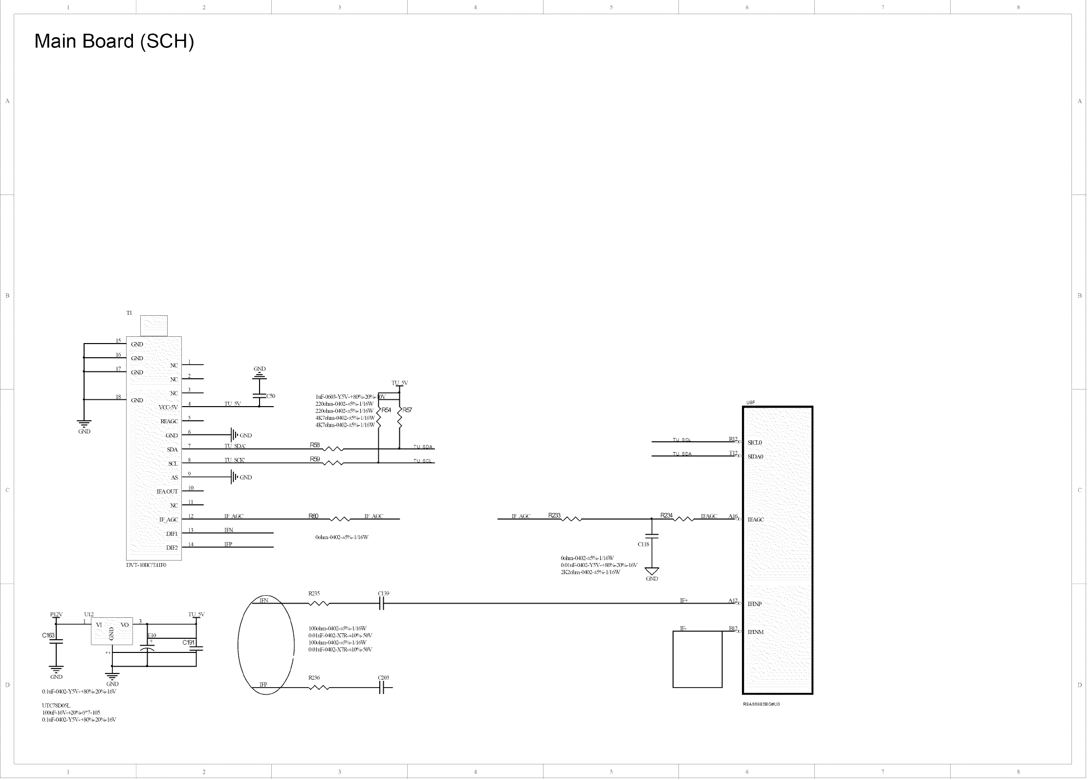
TI
_B
15
16
17 NC --
GND
NC
N_2-
18 GT,]D
1
G_'D
2
3 @(50
4TU _%_
5
htF-0603-'12%'- +80%-2(P, b-
220ohm-Od02-_5%- 1/16TV
220ohm-Od02-_5%- H 6TV
4K7@an-{MO2-+__%-Iq 6TV
5
4K7@an-0102-+2 %- I'I6TV
O'ND
SDA
x
iii /i_
x DIF1
5 x i
D\T- IOBCq'41F0
6 11,G_'D
7 TU SD_
8TLJ S(K'
9 11' O_D
10
11
12 IF ACRP
13 IFN
R58 ,/X/X,
R59 ./XA. •
14 11_
R235 CI39
PI2V UI2 TU _%:
_-_ VI _ VO _+i0 I 100ohln-('_}2-_5%- 1/16TV
G't _ 0 0htF- 0_2-X7R-±t 0%- 50\,
C1 100ohm-('_}2-_5%- H6W
T i r T_- 0 0hlF- 0!02-XTR-±t 0%- 50\,
O%'I) _ R236 {7203
0 hff'-OtO2-Y%_- +8(P,b-20% - 1o%"
UT{778D05L *
100uF- 16V-+20%-6 7-105
0 hff'-0_2-Y%'- +80%-20%- 1o%"
TU 5V
0V
1TU SDA
Ttd _9_,
Ttd _DA
IF AC<"
R238"A/X" 1 FgN'A/X"
0ohm-0d02-_5%- 1/1oWV I
0 0hff'- 0t02-Y52,c+ 80%-20%- 16_,
2K2olmi-O_2-+-_%- H 6TV V
G_'D
IF+
IFAGC
IF-
Pa_
TI2_
AI¢>
A12_2
BI2;>
U8F
IFAG{-"
i iiiiiiiiii
x
]
i i
iiiiiiiii
12 3¢5 6 8
1 2 3¢5 G
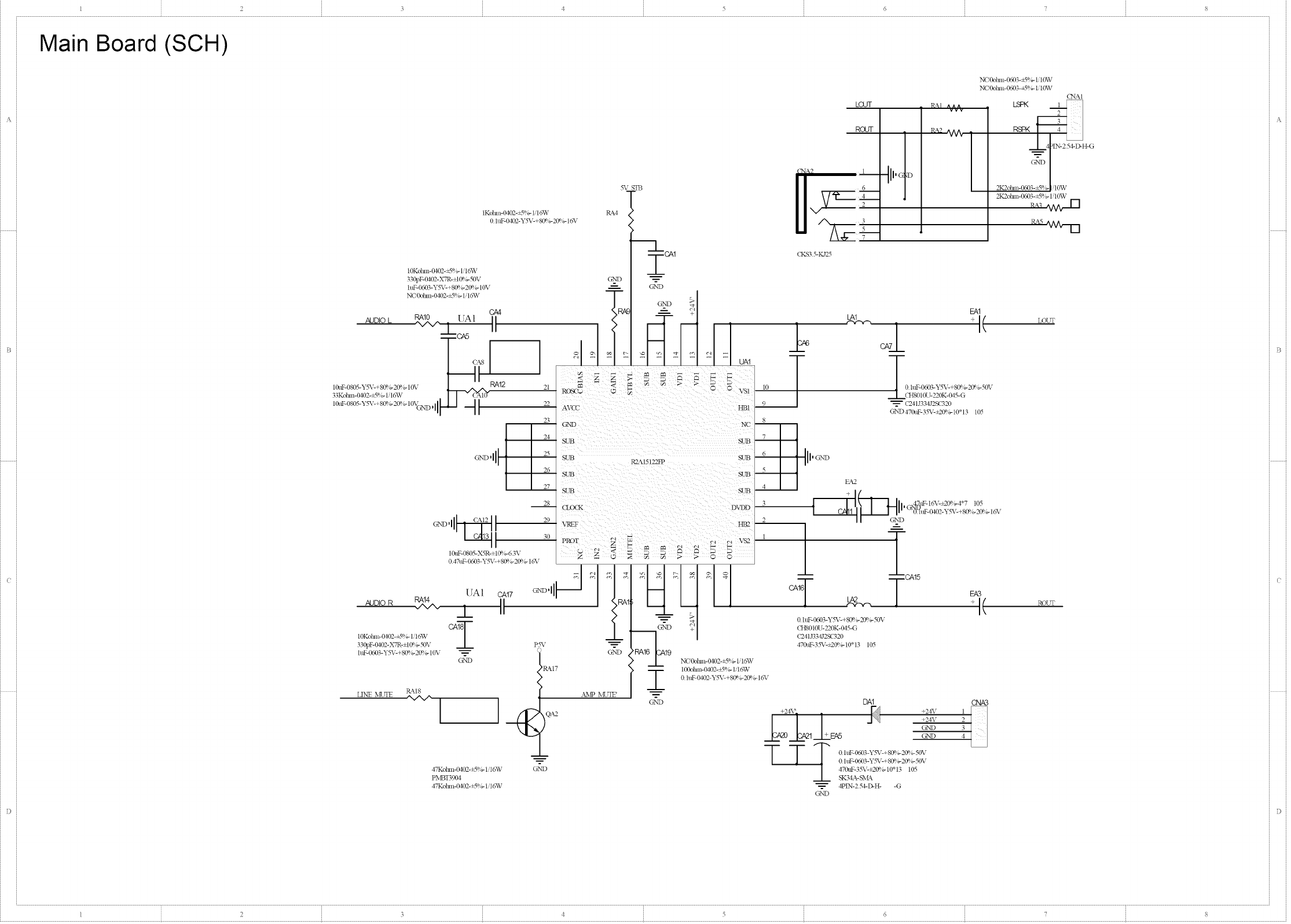
Main Board (SCH)
IKolnn-O_2-+__%- H 6W
0 h_0402-Y5_,c+80%-20%- 16_,
AUDIO L
10Kolml-O_2-_5%- Iit6W
330pF-_O2-X7R-±I0q b-50V
htF-0603-YSX--+80%-20%- 10V
NC'Lbhm-0402-=5%- 1/16_V
10tflz-0805-Y5V-+ 80%-20%- 10V
33Kohm-( '_)2-_5%- H 6_V
28
30
10tiF-0805-XqR-±t 0%-6.3V
0471tF-0603-Y5_,c+ 80%-2(B b-16_,
UA1 CA17
AUDIO R RA14_ i II
IOKolnn-0402-*5%- Iit6W CAI
330pF-0402-X7R-±I 0%-50V
htF-0603-Y5_,_+ 80%-2(Bb- 10\,
GND
LINE MUTE RM8
'N/N/'
5V STB
RM
G%_D
LOUT R_,I
RaJr RA2
6
4
2
3
5
7
(KS3 5-IC125
m
G%_D
NC'Ooln m 0033-+3%- 1/t0W
NC'Ooln n- 0603-+3%- 1/10W
(NAt
F-"'__H_O
2K2ohm-Wo03-_5%- Ii10W
100ohm-_02-+__%- Iit6W
0 htF-0dO2-Y5_,c+ 80%- 20%- 16_,
_'RM7
}&_p MUTE' G_'!','D
tA1 __ (
2A6
__ (241J334,12sc320
GkND470ttF-35V-+20%- 10* 13 105
8
-- -- CA15
CAle
tAP_
0 htF-0603-Y5V-+ 80%- 20%- 50V
CH8010U-220K-04_-G
(241 J334J2SC320
470uF-35V-=20%- 10" 13 105
ILLI
QA2 +24V +24\
+24\
OND
EA5 OND
TTT0htF-0603-YS_,_+80%-20%-50\,
_-- 0 htF- 0603-YSX--+80%-20%- 50\,
47Kolnn-(g(P_-+3%-lq0%V G_'!','D | 470uF-35X--+20%-10*13 105
PMBT390_, _ SK34A- S_A_
47Koln n-0_2-+-5%- l q O%V _ 4PIN-2 5&D-H- -G
GND
LOUT
Ea3
q- ( ROUT
CNA3
1
2
3
4
,%
1 2 3 ¢ 5 6 8
I 2 3 4 5 6
Main Board (SCH)
Diff. pairig_edancel00ohm
<ON3
G%_D
AI 5X
©
I Pd36
21 SH_2
23 SHELIA tlP DET
+5V
G2"D
DIX" DATA
DK<LK
Xc --
CE Remote
CK-
CK Rfidd
OK+
I)0-
n0 Stfield
I30+
D>
D1St_ld
DI+
D2-
D2 Slfield
22 SHFAdB D2+
SHFAI1
471511051
19 AHP{_
18 A1 {V
17 G2N'D
16
15
14
13
12
11 G2N'D
10 AR_<Qp
9AR_<QM
G%_D
AR_<gP
6AR_<IM
5 G%,'D
4 AR_qP
3ARX2M
2G%'D
1AR_<_p
A_A
ASCL
10Kolm>0402-_5%- Ii15W
Q_gl 47Kolm>0402-_5%- 1/16W
AR_<QM 47Kolm>@D2-_5%- Ii16W
OND
<ON4
21 SHELL2
23 SHFJ_LA tlP DET
÷5V
6_n
DIN'DATA
DDCCIX
XC--
_-ERemote
(K-
17KShield
<K+
I:)0-
D0 5tfield
D0+
D1-
D1St_ld
DI+
D2-
22 D2 Slfield
SHFAdB D2+
SHFAI1
471511051
19 _HP_
18 _I {V
17 G%,'D
16 _A
15 _Q_
14
13 CECl
12 BRXCM
11 G%'D
10 _R_QP
9_RXQM
8G%'D
7_RXQP
6_RX1N
5G%'D
4_RX1P
3BRX2M
2G%'D
1#R_P
G%'D
R184 Pd65
10Kolm>0402-+5%- lq6W
47Kolm>_2-+5%- lq6W
47Kolm>0402-+5%- lq6W
OND
M3 3V
L8
120olm>0603-+25%
HDNA 33V
t
OND
4R7ohm-lM02-+5%- Ii16W
4R7ohm-lM02-+5%- Ii16W
4R7otml-_02-+5%- IiI_V
4R7otm_-_02-+5%- IiI_V
4R7otm_-_02-+5%- IiI_V
4R7otm_-_02-+5%- IiI_V
4R7otm_-_02-+5%- IiI_V
4R7olm_-@D2-+5%- IiI_V
040 Do+ ,/_/_ R221 _:
O40 Do- ,/N/N R222 A;
040 [31+ ,/N/N R223 B2 L
o40 D_- ,/N/N R224 aQ_.
CH0 D2+ _VN R225 BI_:
CN0 D2- ,/N/N R226 AL,
CNO CLK+ ,/N/N R227 B4,
CH0 CLK- _R228 A4
CH0 SCL 05 CI6_
CH0 SDA C5 CI_>
PWR R20%N/N_
IKdm>0402-_S_gli16W
IVII2__
0 0 hff:-0402-XTR-±t if%-50V
560@an-0_2-±1%- HoWV
RXOM AVDD33V
RX1P N
(214
RX2P
EXT RKS _C4
_M m
PLL XFC A <<:
]%X(P
DEK'__KL C128 RI86
C130
C135 S - -
3Kohm-lM02-_5%- 1/16'vV_-_'-
2200pF-O_(P_-X7R-±I0°_-53%_q3
4700pF-0402-X7R-±I 0%-50V
2K2olmi-0402-_5%- 1/16W
2 2ttF-0603-Y%'-+80%-20%- 10V
1080 IC82 1091 1094 IC95 1097
T T T T T T
10 u F43805-X 5 R-::= 10%-6 3V
0 1uF-0402-Y5V-+80%-2:0'F_.F'_402-Y5V-+80%-20°/g11&_F-0402-Y5V-+80%-20%-16_1uF-0402-Y5V-+80%-20%-16V
0 1uF-0402-Y5V_80%-20%-16V 0 1uF-0402-Y5V480%-20%-16V
Diff. pairi_oedanoel00ohm
CON1
21
23 SHELL2
- SHELIA tlP DET
+5V
6%'D
DIX" DATA
DDCCLK
XC --
CE Remote
CK-
(2K _field
OK+
1)O-
nO _ield
DO+
Db
D1N_ld
DI+
D2-
22 D2 Shield
SHF3d_ D2+
SHELL1
471511051
OND
CON2
21 SHF3!2
23 SHELIA HP DET
÷5V
6>'D
DIX'DATA
DDCrLK
XC-
tTERelnote
CK-
ffK Shidd
<K+
D0-
DO S_ld
DO+
DL
D_e_eld
DI+
D2-
22 D2 Shield
S_dd3 D2+
SHELL1
471511051
OND
19
18
17
16
15
14
13
12
11
10
9
8
7
6
5
4
3
2
1
G%'D
G%'D
G%'D
G%'D
G%'D
QHP#
ql _V
O_A
O_g_
Oggl
QRKQM
QRKQP
QRKOM
QRKOP
QRKIM
CRXlP
QRK_M
QRKaP
19
18
17
16
15
14
13
12
11
10
9
8
7
6
5
4
3
2
1
_HPP
Pl 8Y
G_ND
DSDA
G%'D
G%'D
G%'D
G%'D
gggl
_RXQM
_RXQP
_RXOM
_RXOP
DRXIM
_RX1P
_RXaM
_RX2p
G%'D
C[ 5X
85 R199
10Kolm>0402-+59g 1/16W
47Kolm>0402-+59g 1/16W
47KolmY0402-_5_g 1/ISW
G%'D
>92
R208
10Kolm>0402-+5%- Ii16W
47Kolm>_2-+5%- Ii16W
47KolmY0402-+5%- lil_vV
BRXCM
BRXCP
BRXOM
BRX0P
BRXIM
_RX1P
BRX2M
BRX2P
ARXCM
ARXQP
ARXOM
ARXgP
ARXIN
ARXIP
ARX_N
ARXaP
INIDln IN4D4p
IN1D3p z
VCr
INIDdn
=
G%'D
IKohm-0d02-+5%- 1/16W
36Kohm-( _(P_-+5%-1/1oWV
36Kohm-0402-+s%- t/1o%V
1Kohm-0d02-+5%- 1/1oWV
U7
P_21
50
22t tF-Wo03-Y%_-+80%-2ff% - 10V
m
9R_aP
CRX2M
O HDN_ 33V
CRXIP
QR_IN
CRXOP
CRXOM
CRXCP
CRXCM
DRX2P
DRX2M
PR_IP
DRXIM
DRX0P
DRXOM
PR_QP
DRXCM
--___-----
G%'D
IKolmY0_2-+5%- Ii16W
499olun-0d02-±I%- H6W
Title
G2X'D Date: 2011-01-07 I Sheet of
i
File: D:',ATK'C,P10 HDIMI.SclE_oc ID_awn By,:
I 2 3 ! 5 6
Power Board (PCB)
OLP
8LgB
_9
_:)o
ra 0
0
_9_ 0
0
0
0
gn
"HX" P054C042A<AYP418101-029 REV:I.0> CEM-1 1.6T 2009.0808 4PCS "S" 191.5'136MM <2010.0320>
L
F
{
0
[=1
ZOB
£r
I
LNO0
T
F1
_P
-[ }-
LO
4 I-
-I,q
L o J
Power Board (PCB)
mm miO|
O [] m •o []mUm ( ill
O nO mmmmmm m- •
Power Board (PCB)
"HX" P054C042A<AYP418101-029 REV:I.0> CEM-1 1.6T 2009.0808 4PCS "S" 191.5"136MM
-4
_-_ I-I-II-IM El II
'' ' i I i m
, _ UUU aU no_
_" U I-I-I LL o_o U
91-1 III I-1
U _ _ U
F-1
L_I
V-1
ga LI
F o
E _3E_-I
E3E3
V-E1
III
[qrq
E _v6_. UU
III n
og_
U
£gag_o g6_ Ho go
_F1F1F1F1 F1
r-fir-El _r_
_01-1 I--1 I--1U
U
_o,r--_U _o U
_,6;9 I__ d _ga t,ga
E3_L_?_E]
L
0UU0000
mr-_
uul_
I--I_ oi-1
u_o
i_1 I-I1-11-1
I-I1-I1-i
gza r-lr-1
_U
N
°)_L_ o Lo
u
j-1 I-1I-1I-1
_U000
g6;s 66W
[qrq
UU LoINO0_
UU
nn
uu
LO1._180l_
0
£lo
F1
u_
/
Power Board (PCB)
"HX" P054C042A<AYP418101-029 REV:I.0> CEM-1 1.6T 2009.0901 4PCS "S" 191.5"136MM
IAYP418101 REV: 1.0
I
I
J
Lo/
Power Board (PCB)
"1-_' PO54CO42A<AYP4L8LOI-029 R_fl/':l.0> C_-1 1,8T 2009.0808 4PCS "S" I91.51L36MM
03.8_ -_ -_
•"4 4 4
4
-_-_ __ _0 4
4 4
-0 -0
4-_ -_ -_ -0_
-_ 4-_ -_ -0
-0 -0 -_
4
0 _.8__ * ÷
-F
+++:
¢.,,,,
+; -_
_1_ ._ -_-F--_-F-
-F
-F
@
++:+
I
¢
T f_, r_ r_
_, ; .,_\:t T
Power Board (SCH)
I1N'pUT 90 264VAC [
26" EXPLORED VIEWING
®
®®
®
o
B
7
6
5
4
3
2
!
No.
ST3XBF
5T3XSF-SJZB22
ST4XIOF
ST4X12F
MSXI2
M4X8
192697000
PCB-KEY-3292
143293100
14329B200
430840001
243292100
143292800
103292000
420807001
143296100
]B42KlSO0
122896020
262680000
[63292100
183292000
183292100
212896300
PCB-DYB-2898
23329801C10
252696000 Bracket 1
213223330 Connecter 4
31265500 ! Rubber 4
Y4 l5 - 1604 Speaker 2
162292200 Bracket speak_ " 2
.CO*26-CIO-¥Z6061-LII Panel l
PCB- IR-4293 IRboard 1
t71930100 Lens sensor 1
I 12697000 Front cabinet 1
Pa_# Name Amount
I I I I I I
IIII I I I
li,I,l,I I I
III II I l_Izl
[14 I Is I161f r TIIT r _ T T,, I T
