RCA Direct View Digital 27 To 40 TV Manual 99020008
User Manual: RCA RCA Direct View Digital 27 to 40 TV Manual RCA Direct View Digital 27 to 40 TV Owner's Manual, RCA Direct View Digital 27 to 40 TV installation guides
Open the PDF directly: View PDF ![]() .
.
Page Count: 32
CONNECTIONS
GUIDE
To Find
Your Hook-up
Turn To
Page 1
Connecting TV to Antenna (or Cable Without Cable Box) and
No VCR (Hook-up 1A) ................................................................................................. .2
Monaural VCR (Hook-up 1B) ...................................................................................... .3
Stereo VCR (Hook-up 1C) ............................................................................................ 4
Cable With Cable Box Required for All Channels and
No VCR (Hook-up 2A) .................................................................................................. 5
Monaural VCR (Hook-up 2B) ................. :..................................................................... 6
Stereo VCR (Hook-up 2C) ............................................................................................ 7
Cable With Cable Box Required for Some Channels and
No VCR (Hook-up 3A) .................................................. :............................................... 8
Monaural VCR (Hook-up 3B) ...................................................................................... 9
Stereo VCR (Hook-up 3C) ........................................................................................... 10
Satellite, Cable, and
No VCR (Hook-up 4A) ................................................................................................ 11
Monaural VCR (Hook-up 4B) ..................................................................................... 12
Stereo VCR (Hook-up 4C) ........................................................................................... 13
Satellite, Antenna, and
No VCR (Hook-up 5A) ................................................................................................14
Monaural VCR (Hook-up 5B) .....................................................................................15
Stereo VCR (Hook-up 5C) ...........................................................................................16
Audio System ......................................................................................... 17
Ordering Accessories Cables and Adapters ..................................................................... 18-19
Order Form .......................................................................................19-20
References Guide to Connection Panel .............................................................. 21
Things to Know Before Connecting Cables ............................... 22
Protect Your Components from Power Surges
Avoid Audio Hum by Positioning Cables Correctly
Protect your Components from Overheal_ag
Connect Audio/Video Cables for Best-Results
Trouble Checks ............................................................................... 23-27
Glossary ........................................................................................... _-29
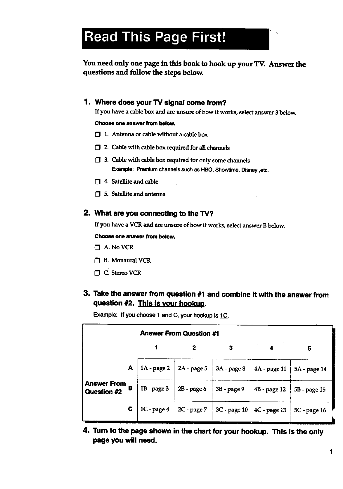
You need only one page in this book to hook up your TV. Answer the
questions and follow the steps below.
1. Where does your TV signal come from?
If you have a cable box and are unsure of how it works, select answer 3 below.
Choose one answer from below.
O 1. Antenna or cable without a cable box
1_ 2. Cable with cable box required for all channels
[_ 3. Cable with cable box required for only some channels
Example: Premiumchannelssuchas HBO, Showtime,Disney,etc.
O4. Satellite and cable
[_ 5. Satellite and antenna
2. What are you connecting to the TV?
If you have a VCR and are unsure of how it works, select answer B below.
Choose one answer from below.
0 A. No VCR
0 B. Monaural VCR
OC. Stereo VCR
3. Take the answer from question #1 and combine it with the answer from
question #2. _[1_.
Example: If you choose 1 and C, your hookup is 1C.
Answer From Question #1
1 2 3 4 5
A1A-page2 2A-page5 I 3A-page8 !4A-page11 I 5A.page14
Answer From B 1B - page 32B - page 6 , 35 - page 9 4B - page 12 5B - page 15
Question #2 !
I
C 1C-page4 2C-page7 !3C-page10 4C-page13 5(2-page16
! i
4. Turn to the page shown in the chart for your hookup. This Is the only
page you will need.
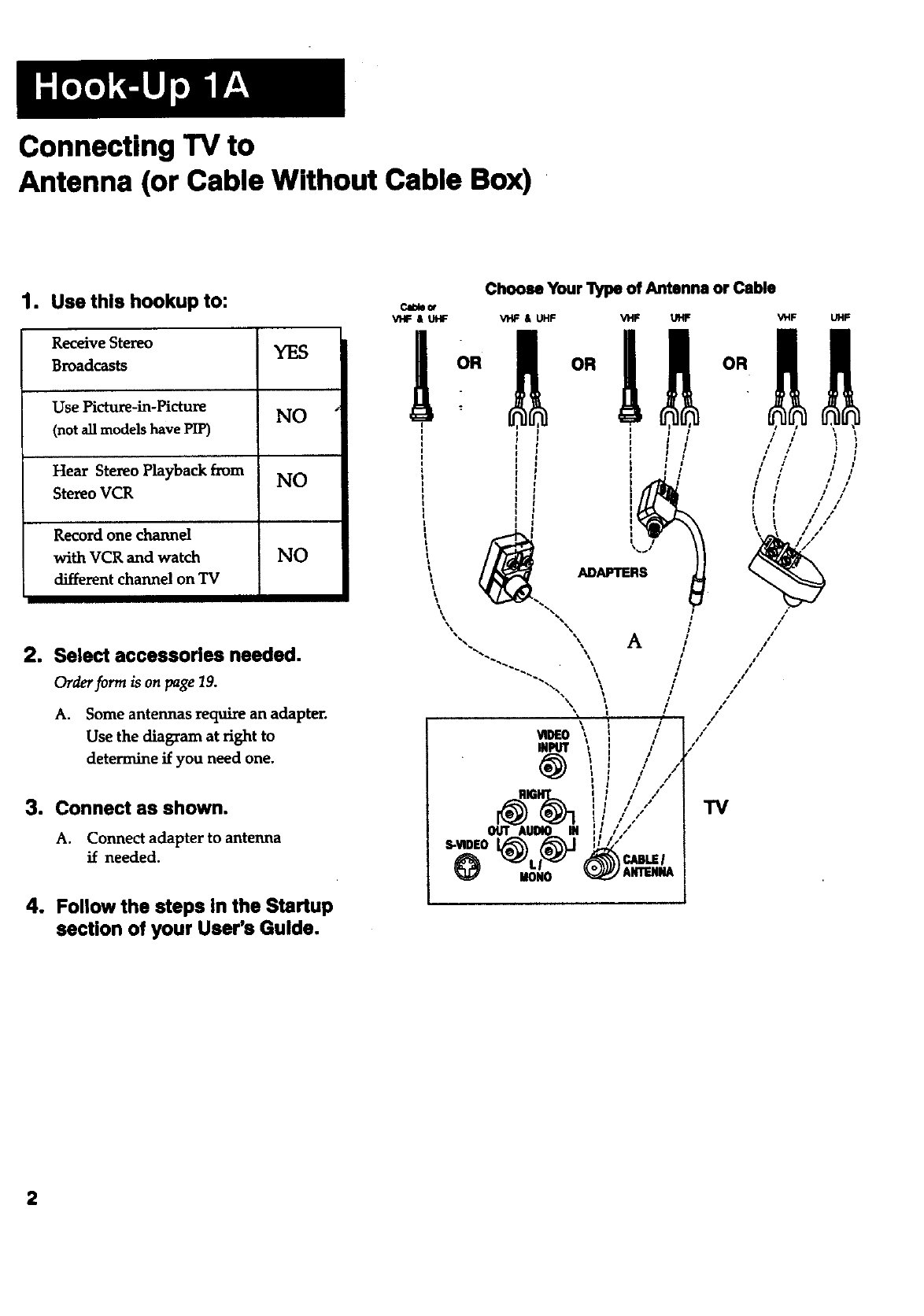
Connecting "IV to
Antenna (or Cable Without Cable Box)
1. Use this hookup to:
ReceiveStereo YES
Broadcasts
Use Picture-in-Picture NO
(not all models have PIP)
Hear Stereo Playback from NO
Stereo VCR
Record one channel
with VCR and watch
different channel on TV
NO
2. Select accessories needed.
Order form is on page 19.
A. Some antennas require an adapter.
Use the diagram at right to
determine if you need one.
3. Connect as shown.
A. Connect adapter to antenna
if needed.
4. Follow the steps in the Startup
section of your User's Guide.
Choose Your _of Antenna or Cable
V'HF & UHF VHF & UHF Vt_ UHF VHF UHF
"IV
S-VIDEO
IlONO
2
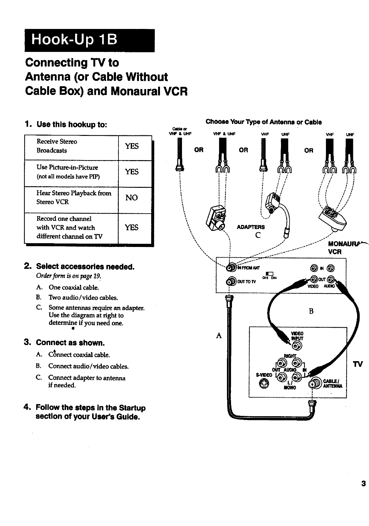
Connecting TV to
Antenna (or Cable Without
Cable Box) and Monaural VCR
1. Use this hookup to:
Receive Stereo YES
Broadcasts
Use Picture-in-Picture YES
(not all models have PIP)
Hear Stereo Playback from NO
Stereo VCR
Record one channel
with VCR and watch YES
different channel on TV
2. Select accessories needed.
Order/orm is on page 12.
A. One coaxial cable.
B. Two audio/video cables.
C. Some antennas require an adapter.
Use the diagram at right to
determine if you need one.
3. Connect as shown.
A. C_nnect coaxial cable.
B. Connect audio/video cables.
C. Connect adapter to antenna
if needed.
4. Follow the steps in the Startup
section of your User's Guide.
Choose Your "1_ of Antenna or Cable
Cable_
VHF & UHF VHF & UHF
OR
MONAURP'_
VCR
A
B
TV
3
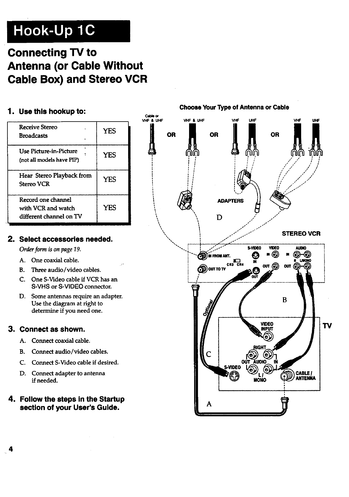
Connecting TV to
Antenna (or Cable Without
Cable Box) and Stereo VCR
1. Use this hookup to:
Receive Stereo YES
Broadcasts
Use Picture-in-Picture :YES
(not all models have PIP)
Hear Stereo Playback from YES
Stereo VCR
Record one channel
with VCR and watch YES
different channel on TV
2. Select accessories needed.
Order form is on page 19.
A. One coaxial cable.
B. Three audio/video cables.
C. One S-Video cable if VCR has an
S-VHS orS-VIDEO connector.
D. Some antennas require an adapter.
Use the diagram at right to
determine if you need one.
3. Connect as shown.
A. Connect coaxial cable.
B. Connect audio/video cables.
C. Connect S-Video cable if desired.
D. Connect adapter to antenna
if needed.
4. Follow the steps in the Startup
section of your User's Guide.
Cl_or
VHF & UHF
OR
Choose Your Type of Antenna or Cable
/
TV
4
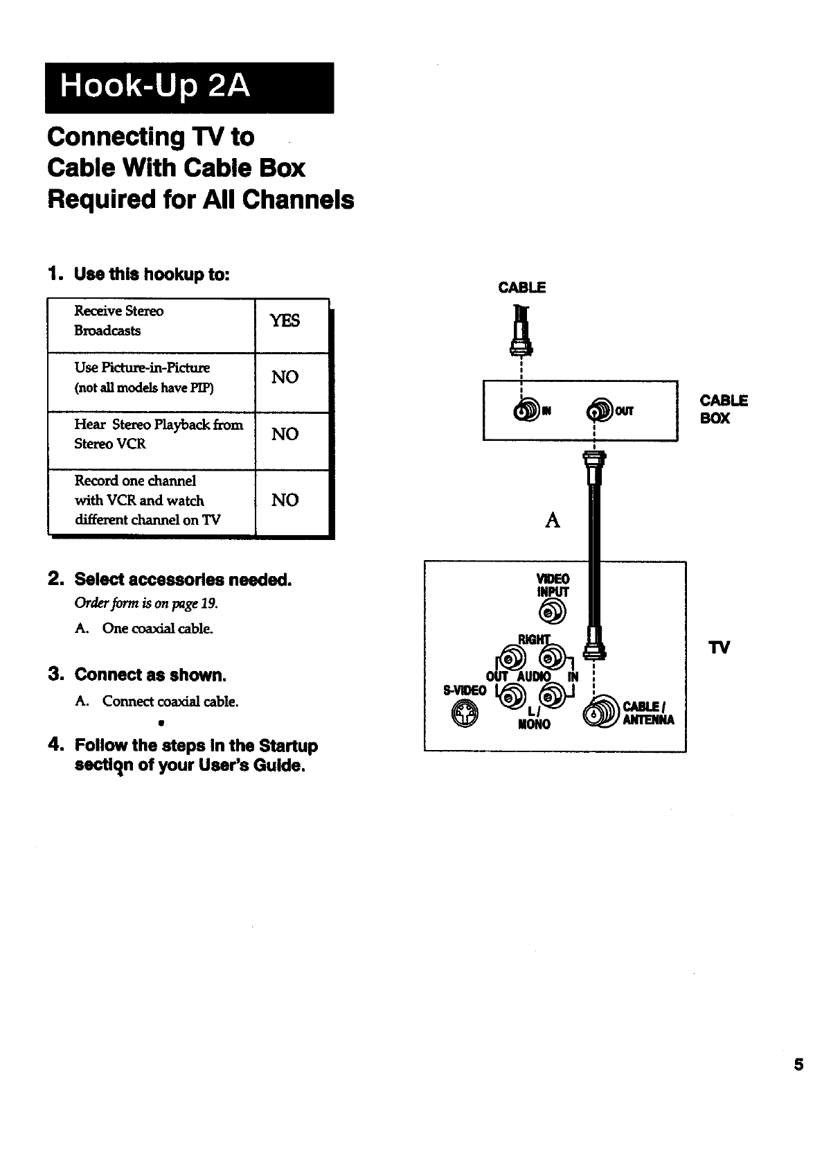
Connecting TV to
Cable With Cable Box
Required for All Channels
1. Use this hookup to:
Receive Stereo YES
Broadcasts
Use Picture-in-Picture NO
(not all models have PIP)
Hear Stereo Playback from NO
Stereo VCR
Record one channel
with VCR and watch NO
different channel on TV
2. Select accessories needed.
Order form is on page 19.
A. One coaxialcable.
3. Connect as shown.
A. Connect coaxial cable.
4. Follow the steps in the Startup
sectlqn of your User's Guide.
CABLE
A
!
I
Ii
I
_. _ cABLE
BOX
A
i
_IOE0
TV
%0 -,
@ @_,.
5
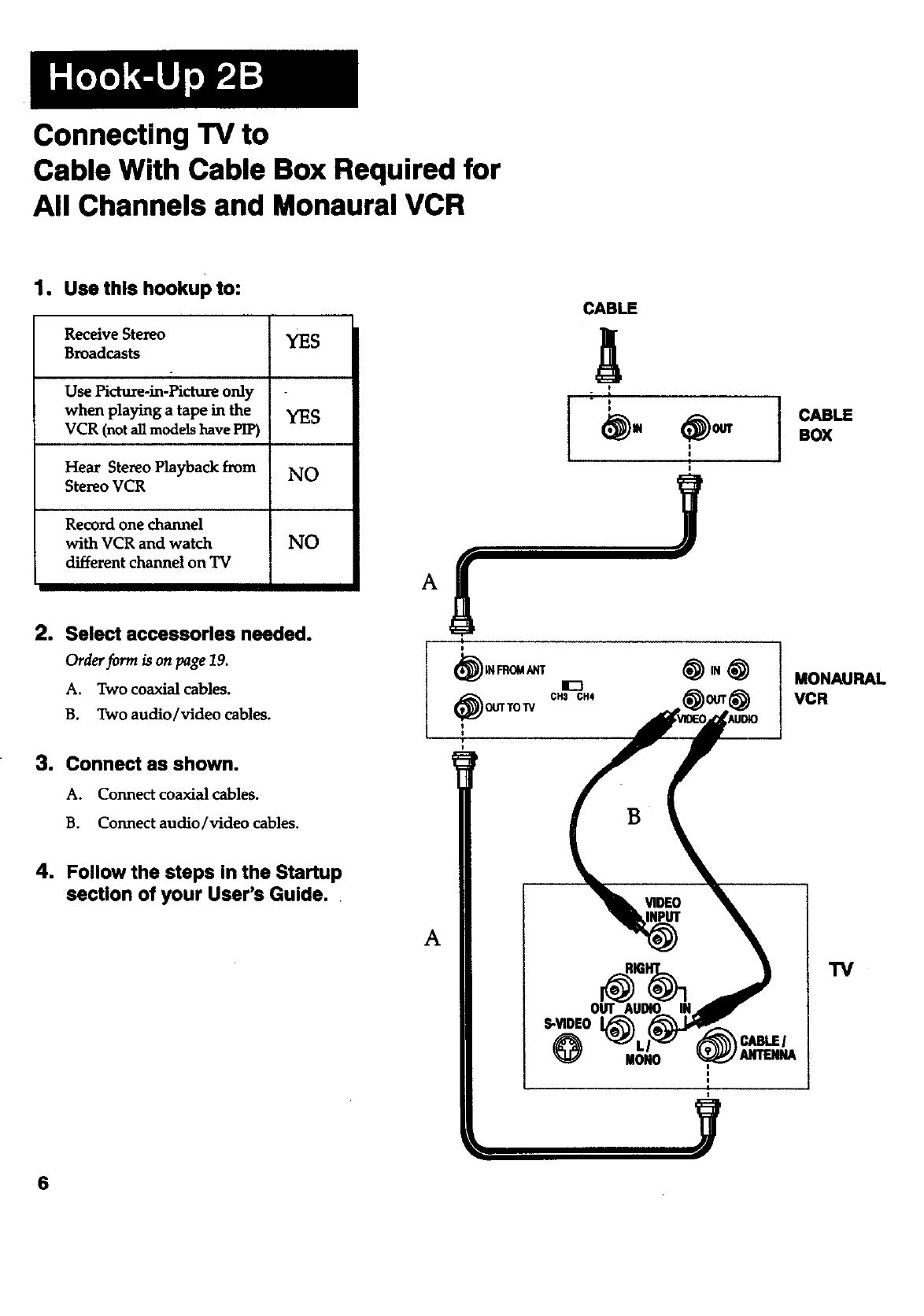
Connecting TV to
Cable With Cable Box Required for
All Channels and Monaural VCR
1, Usethis hookupto:
Receive Stereo YES
Broadcasts
Use Picture-in-Picture only
when playing a tape in the YES
VCR (not all models have PIP)
Hear Stereo Playback from NO
Stereo VCR
Record one channel
with VCR and watch NO
different channel on TV
2. Select acceesorles needed.
Order form is on page 19.
A. Two coaxial cables.
B. Two audio/video cables.
3. Connect as shown.
A. Connect coaxial cables.
B. Connect audio/video cables.
4. Follow the steps in the Startup
section of your User's Guide.
6
CABLE
A
)
I
(_IN FROMANT
_. (_OUTTOW
CH$ CH4
B
A
S-VIDE0
IIONO
I
CJUBLEI
CABLE
BOX
MONAURAL
VCR
TV
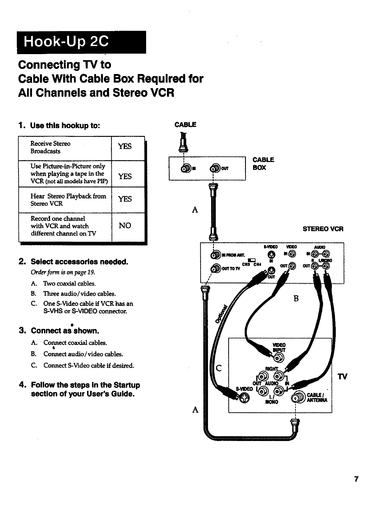
Connecting TV to
Cable With Cable Box Required for
All Channels and Stereo VCR
1. Use this hookup to:
Receive Stereo YES
Broadcasts
Use Picture-in-Picture only
when playing a tape in the YES
VCR (not all models have PIP)
Hear Stereo Playback from YES
Stereo VCR
Record one channel
with VCR and watch NO
different channel on TV
2. Select accessories needed.
Order form is on page 19.
A. Two coaxial cables.
B. 22uee audio/video cables.
C. One S-Video cable if VCR has an
S-VHS or S-VIDEO connector.
3. Connect as shown.
A. Connect coaxial cables.
*
B. Connect audio/video cables.
C. Connect S-Video cable if desired.
4. Follow the steps In the Startup
section of your User's Guide.
CABLE
CABLE
I.ox
A
A
STEREO VCR
TV
7
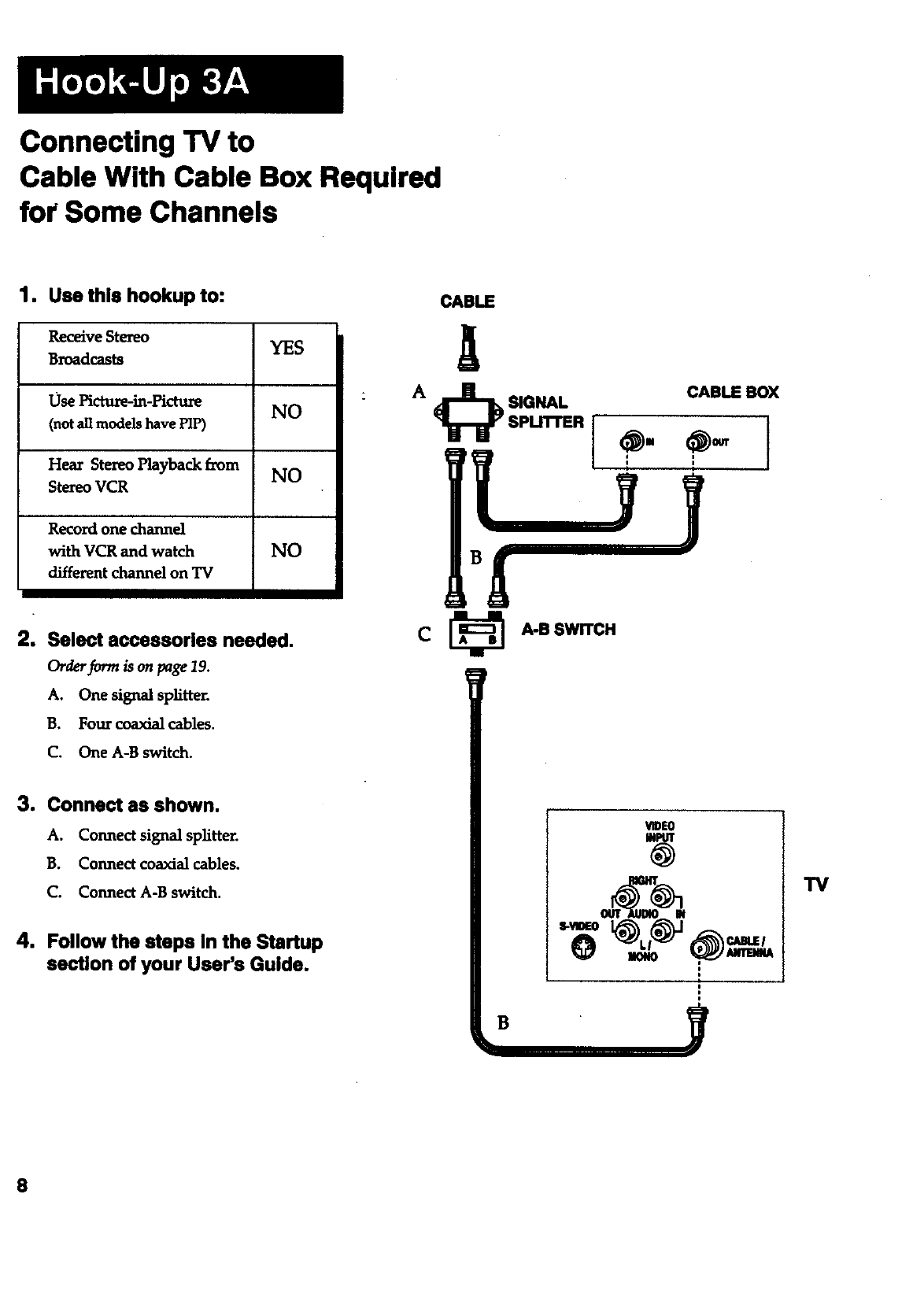
Connecting "IV to
Cable With Cable Box Required
for Some Channels
1. Use this hookup to:
Receive Stereo YES
Broadcasts
Use Pfctu_-m-PictuR NO
(not all models have PIP)
Hear Stereo Playback E_om NO
Stereo VCR
Record one channd
with VCR and watch NO
different channel on TV
2. Select accessories needed.
Order_rrra is on page 19.
A. One signal splitter.
B. Four coaxialcables.
C. One A-B switch.
3. Connect as shown.
A. Connect signal splitter.
B. Connect coaxial cables.
C. Connect A-B switch.
4. Follow the steps in the Startup
section of your User's Guide.
CABLE
CABLE BOX
CA-B SWITCH
VIDE0
t
B
TV
8
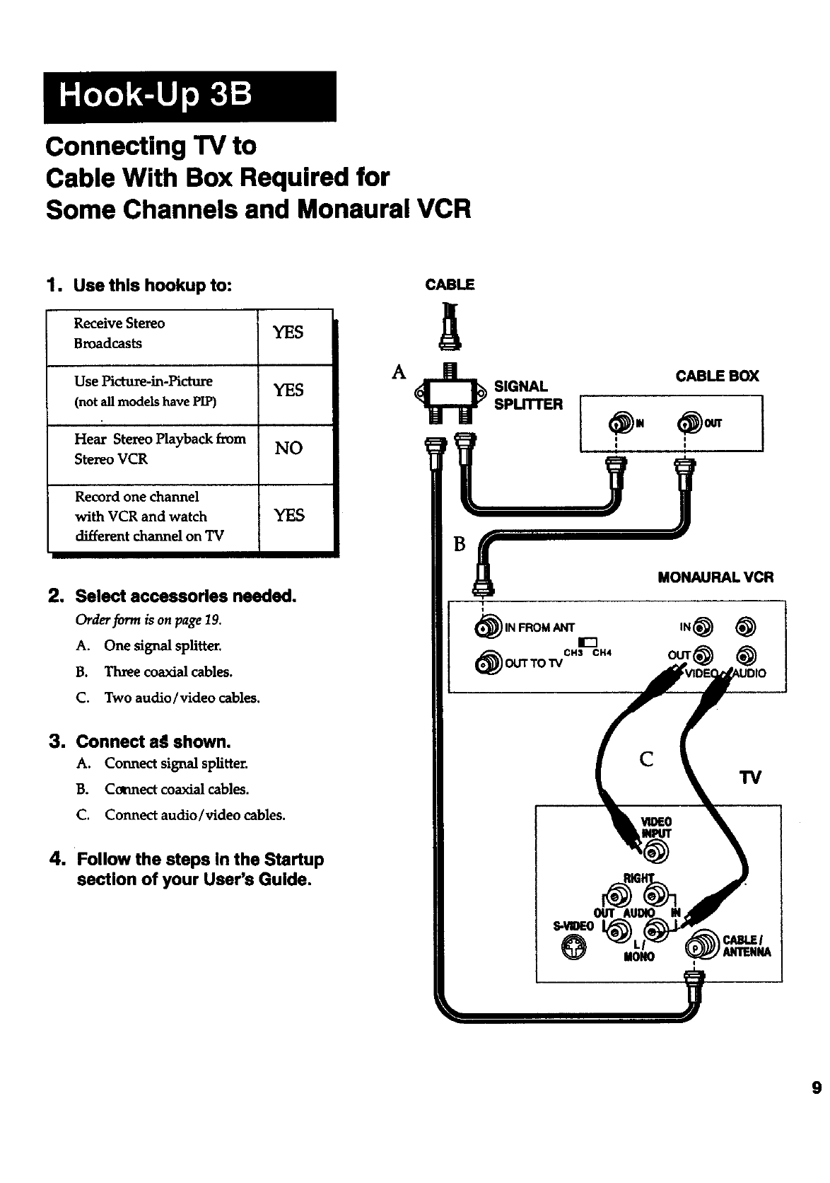
Connecting TV to
Cable With Box Required for
Some Channels and Monaural VCR
1. Use this hookup to:
Receive Stereo YES
Broadcasts
Use Picture-in-picture YES
(not all models have PIP)
Hear Stereo Playback from NO
Ste_o VCR
Record one channel
with VCR and watch YES
different channel on TV
2. Select accessories needed.
Order form is on page 19,
A. One signal splitter.
B. Three coaxial cables.
C. Two audio/video cables.
3. Connect a_l shown.
A. Connect signal splitter.
B. Cormect coaxial cables.
C. Connect audio/video cables.
4. Follow the steps in the Startup
section of your User's Guide.
CABLE
SIGNAL
SPLITTER
CABLE BOX
MONAURAL VCR
(_) IN FROM ANT it-1
(_ CH3 CH4
OUTTo'rv
CTV
MON0
9
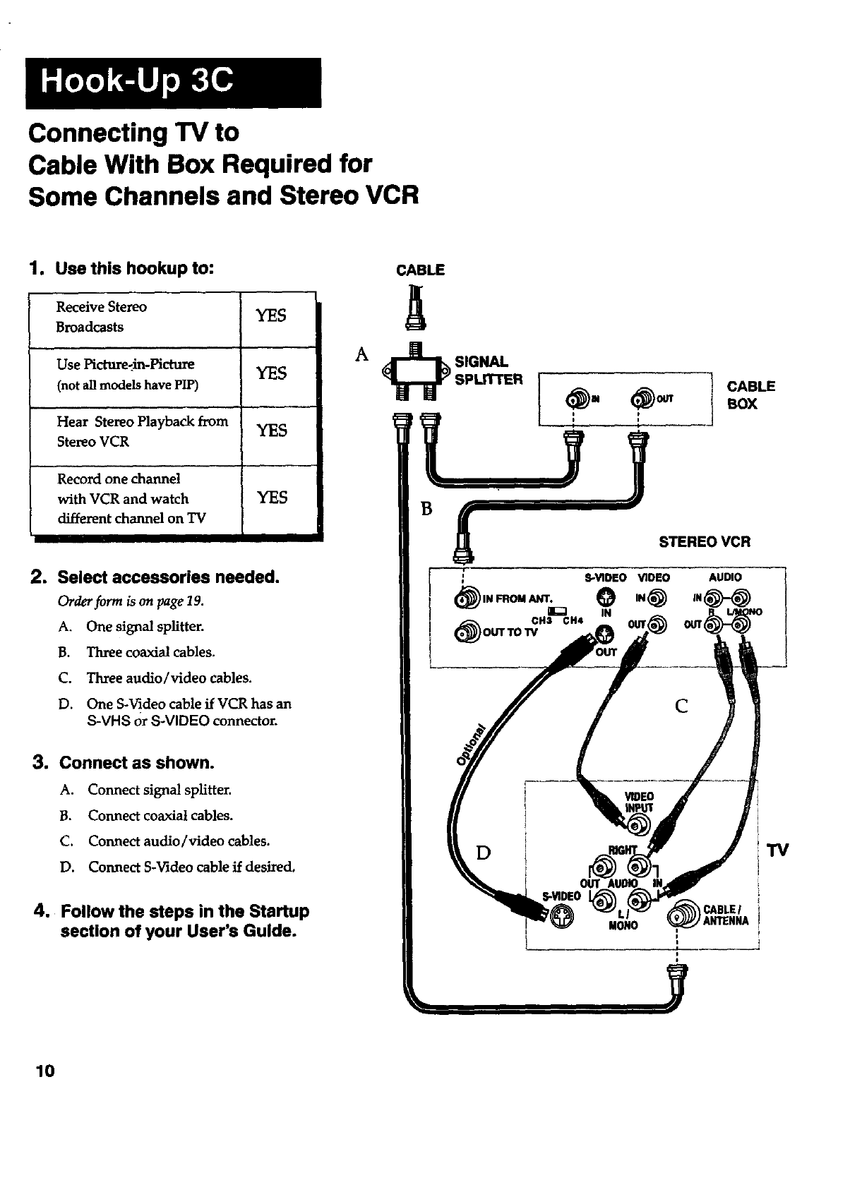
Connecting TV to
Cable With Box Required for
Some Channels and Stereo VCR
1. Use this hookup to:
Receive Stezeo YES
Broadcasts
Use Picture-_in-Hcture YES
(not all models have PIP)
Hear Stereo Playback from YES
Stereo VCR
Record one channel
with VCR and watch YES
different channel on TV
2. Select accessories needed.
Orderform is on page19.
A. One signal splitter.
B. Three coaxial cables.
C. Three audio/video cables.
D. One S-Video cable if VCR has an
S-VHS orS-VIDEO connector.
3. Connect as shown.
A. Connectsignalsplitter.
B. Connectcoaxialcables.
C. Connectaudio/videocables.
D. Connect S-Videocableifdesired.
4. Follow the steps in the Startup
section of your User's Guide.
CABLE
ICABLE
BOX
STEREOVCR
AUDIO
C
"IV
CABLEl
MONO _ANTENNA
10
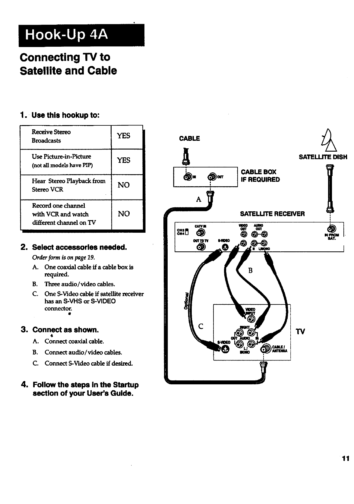
Connecting "IV to
Satellite and Cable
1. Use this hookup to:
Receive Stereo YES
Broadcasts
Use Picture-in-Picture YES
(not all models have PIP)
Hear Stereo Playback from NO
Stereo VCR
Record one channel
with VCR and watch NO
different channel on "IV
2. Select accessories needed.
Order form is on page 19.
A. One coaxial cable if a cable box is
required.
B. Three audio/video cables.
C. One S-Video cable if satellite xeceiver
has an S-VHS or S-VIDEO
connector.
3. Connect as shown.
4
A. Connect coaxial cable.
B. Connect audio/video cables.
C. Connect S-Video cable if desi_d.
4. Follow the steps In the Startup
section of your User's Guide.
CABLE
CABLE BOX
IF REQUIRED
SATELLITE RECEIVER
SATEUJTE DISH
11
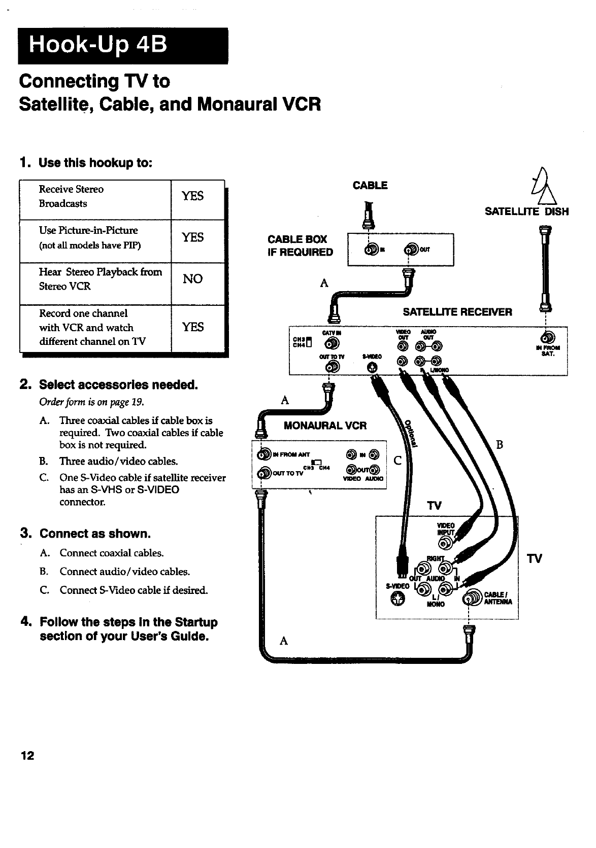
Connecting TV to
Satellite, Cable, and Monaural VCR
1. Use this hookup to:
Receive Stereo YES
Broadcasts
Use Picture-in-Picture YES
(not aUmodels have PIP)
Hear Stereo Playback from NO
Stereo VCR
Record one channel
with VCR and watch YES
different channel on TV
2. Select accessories needed.
Order form ison page19.
A. Three coaxial cables if cable box is
required, Two coaxial cablesif cable
box is not required.
B. Three audio/video cables.
C. One S-Video cable if satellite receiver
has an S-VHS or S-VIDEO
conn_or.
3. Connect as shown.
A. Connect coaxial cables.
B. Connect audio/video cables.
C. Connect S-Video cable if desired.
4. Follow the steps in the Startup
section of your User's Guide.
CABLE
ol,o.
I'I
IF REQUIRED m
SATELLITE RECEIVER
_ E
l
mw i
SAT, i
I
i
B
TV
A
12
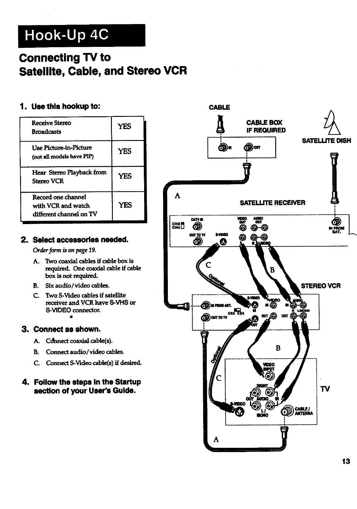
Connecting TV to
Satellite, Cable, and Stereo VCR
1. Usethis hookup to:
Receive Stereo YES
Broadcasts
Use Picture-in-Hcmre YES
(not all models have PIP)
Hear Stereo Playback from YES
Stezeo VCR
Record one channel
with VCR and watch YES
diffe_nt _elon 'IV
2. Select accessorlse needed.
Orderf_rm _ on page19.
A. Two coaxialcablesffcablebox is
required.One coaxialcableifcable
box isnotzequired.
B. Six audio/video cables.
C. Two S-Video cables if satelfite
xeceiver and VCR have S-VHS or
S-VIDEO connector.
I
3. Connect as shown.
A. Connect coaxial cable(s).
B. Connect audio/video cables.
C. Connect S-Video cable(s) if desired.
4. Follow the steps In the Startup
section of your User's Guide.
A
CABLE
CABLE B0_
IF REQUIRED
y
SATELLITE RECEIVER
SATELLITE DISH
B
13
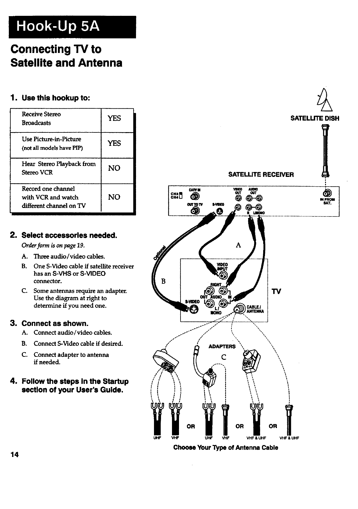
Connecting TV to
Satellite and Antenna
1. Use this hookup to:
Receive Stereo YES
Broadcasts
Use Picture-in-Picture YES
(not all models have PIP)
Hear Stereo Playback from NO
Stereo VCR
Record one channel
with VCR and watch NO
different channel on TV
SATELUTE RECEIVER
SATELLITE DISH
2. Select accessories needed.
Order form is on page 19.
A. Three audio/video cables.
B. One S-Video cable if satellite receiver
has an S-VHS or S-VIDEO
connector.
C. Some antennas require an adapter.
Use the diagram at right to
determine if you need one.
3. Connect as shown.
A. Connect audio/video cables.
B. Connect S-Video cable if desired.
C. Connect adapter to antenna
if needed.
4. Follow the steps in the Startup
section of your User's Guide.
14
A
/
/
/
UHF VHF
I
! \
'iT
OR OR OR
UHF V'rlF VHF & UHF VHF & UHF
Choose Your "l_pe of Antenna Cable
Connecting TV to
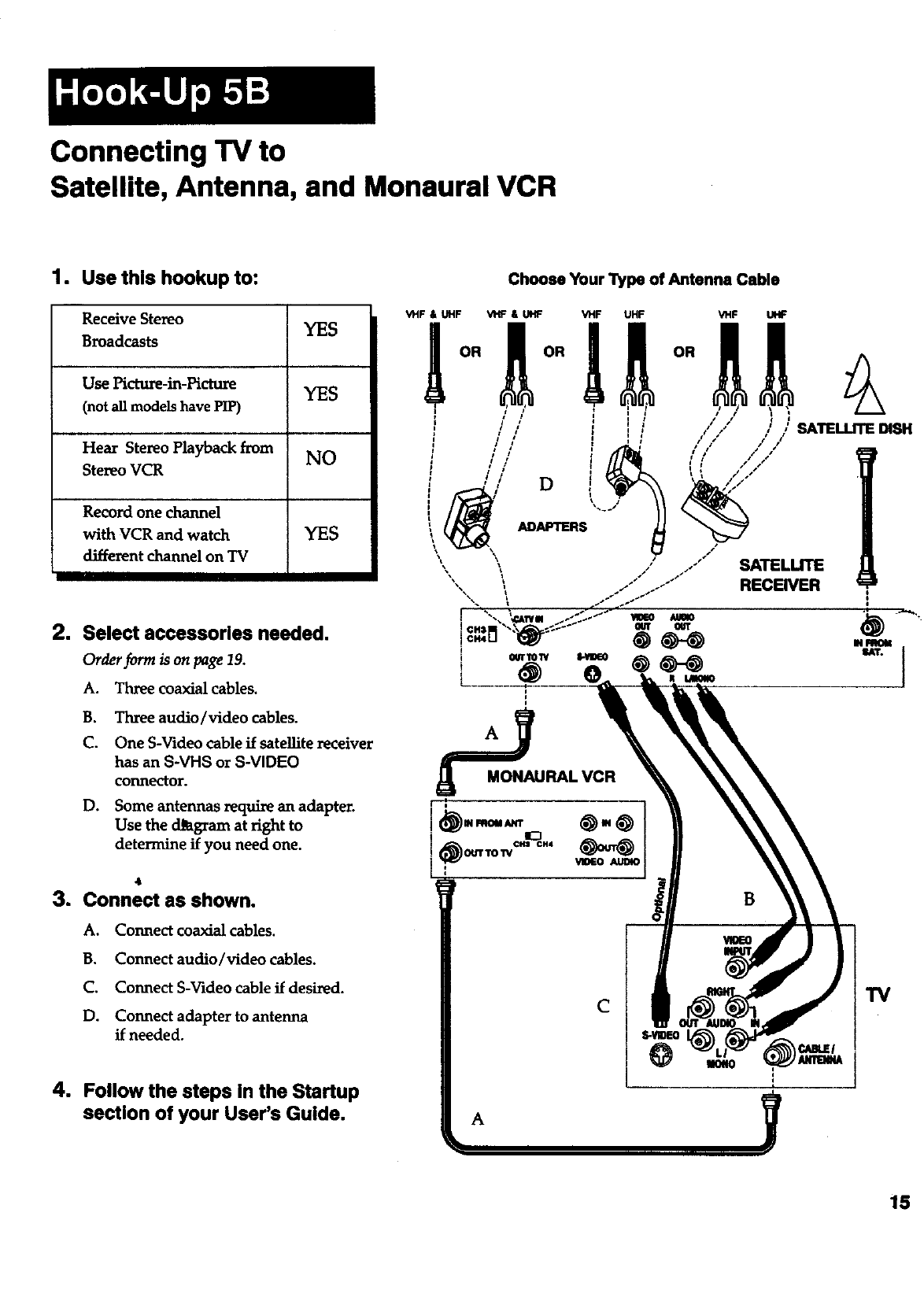
Satellite, Antenna, and Monaural VCR
1. Use this hookup to:
Receive Stereo YES
Broadcasts
Use Picture-in-Picture YES
(not all models have PIP)
Hear Stereo Playback from NO
Stereo VCR
Record one channel
with VCR and watch YES
different channel on TV
2. Select accessories needed.
Order form is on page 19.
A. Three coaxial cables.
B. Three audio/video cables.
C. One S-Video cable if satellite receiver
has an S-VHS or S-VIDEO
connector.
D. Some antennas require an adapter.
Use the d_gram at right to
determine if you need one.
_t
3. Connect as shown.
A. Connect coaxial cables.
B. Connect audio/video cables.
C. Connect S-Video cable if desired.
D. Connect adapter to antenna
if needed.
4. Follow the steps In the Startup
section of your User's Guide.
Choose Your l_pe of Antenna Cable
A
C
15
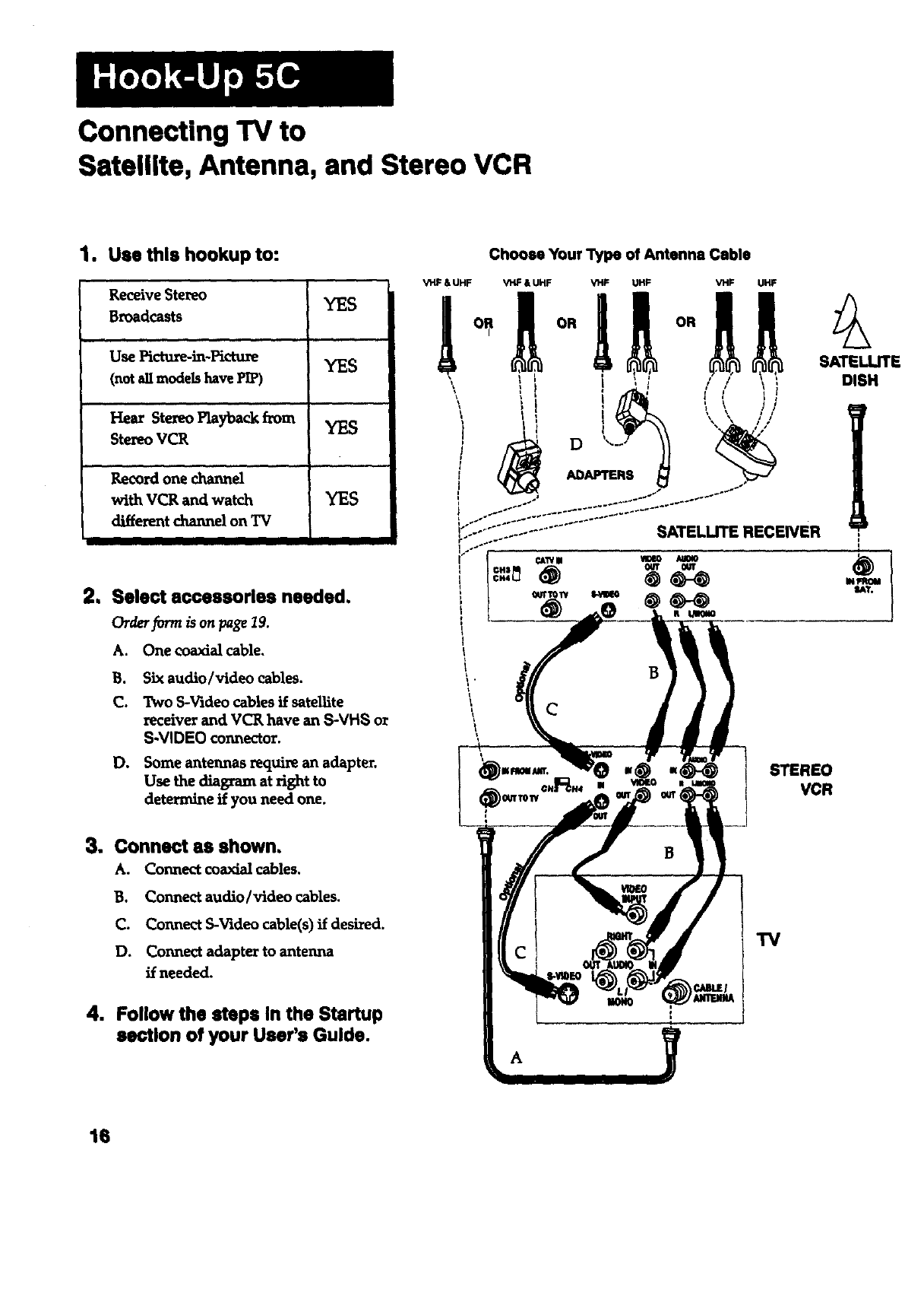
Connecting TV to
Satellite, Antenna, and Stereo VCR
1. Usethishookup to:
Receive Stereo YES
Broadcasts
,, ,,,
Use Pictu_in-Pictu_ YES
(not all models have PI_
' Hear Stereo Playback horn
Stereo VCR
Recordone channel
withVCR and wat_.h YES
different channel on "IV
2, Select accessories needed,
Order form is on page I9.
A. One coaxial cable.
B. Six audio/video cables.
C. Two S-Videocables if sateUite
receiver and VCR have an S-VHS or
S-VIDEO connector.
D. Some antennas require an adapter.
Use the diagram at right to
determine if you need one.
3. Connect as shown.
A. Connectcoaxialcables.
B. Connect audio/videocables.
C. Connect S-Videocable(s)if desired.
D. Connectadaptertoantenna
ifneeded.
4. Follow the steps In the Startup
section of your User's Guide.
VHF & UHF
Choose Your Type of Antenna Cable
STEREO
VCR
TV
16
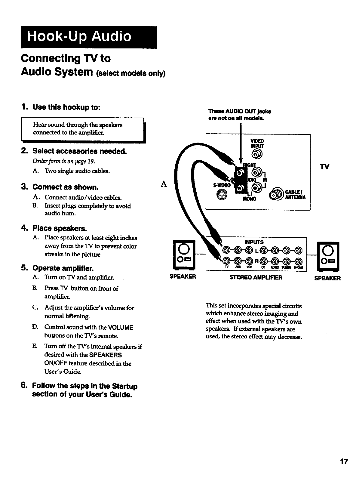
Connecting TV to
Audio System (selectmodels only)
1. Use this hookup to:
1
Hear sound through the speakers |
connected to the amplifier. I
2. Select accessories needed.
Or&,rformisonpage19.
A. Two single audio cables.
3. Connect as shown.
A, Connect audio/_deo cables.
B. Insert plugs completely to avoid
audio hum.
4. Place speakers.
A. Place speakers at least eight inches
away from the TV to prevent color
streaks in the picture.
5. Operate amplifier.
A. Turn on TV and amplifier.
B. Press TV button on front of
amplifier.
C. Adjust the amplifier's volume for
normal li_ening.
D. Control sound with the VOLUME
bulitons on the TV's remote.
E. Turn off the TV's internal speakersif
desiredwith theSPEAKERS
ON/OFF feature deseX_bedin the
User's Guide.
6. Follow the steps In the Startup
section of your User's Guide.
A
SPEAKER
AUDIO OUT Jaokl
are not on ell models.
INPUTS
This set incorporates special circuits
which enhance stereo imaging and
effect when used with the TV's own
speakers. If external speakers are
used, the stereo effect may decrease.
W
SPEAKER
17
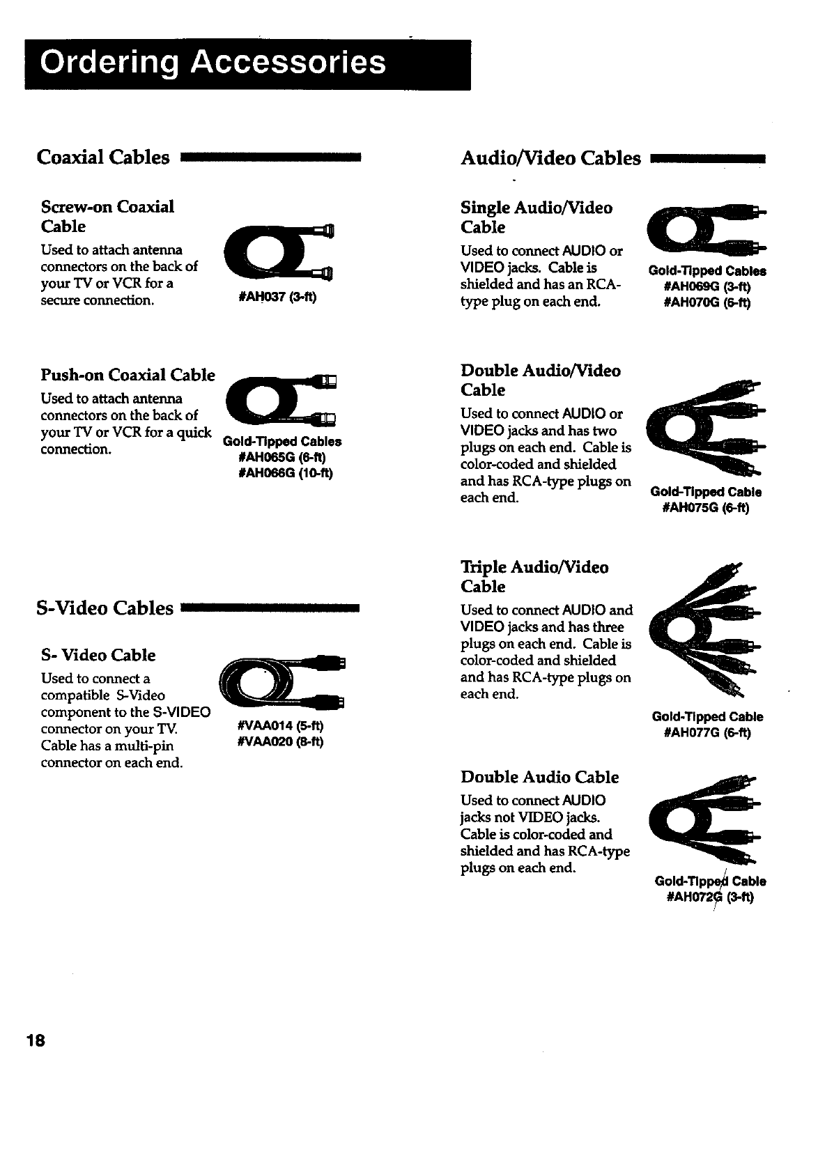
Coaxial Cables Audio/Video Cables
Screw-on Coaxial
Cable
Used to attach antenna
connectors on the back of
your TV or VCR for a
secure connection. #AH037 (3-ft)
Single Audio/Video
Cable
Used to connect AUDIO or
VIDEO jacks. Cable is
shielded and has an RCA-
type plug on each end.
Gold-Tipped Cables
#AH069G (3-ft)
#AH070G (6-ft)
Push-on Coaxial Cable
Used to attach antenna
connectors on the back of
your "IV or VCR for a quick
connection. Gold-Tipped Cables
#AH065G (6-ft)
#AH066G (lO-ft)
Double Audio/Video
Cable
Used to connect AUDIO or
VIDEO jacks and has two
plugs on each end. Cable is
color-coded and shielded
and has RCA-type plugs on
each end. Gold-Tipped Cable
#AH075G (6-ft)
S-Video Cables
S- Video Cable
Used to connect a
compatible S-Video
component to the S-VIDEO
connector on your TV.
Cable has a multi-pin
connector on each end.
#VAA014 (5-ft)
#VAA02O(s-ft)
Triple Audio/Video
Cable
Used to connect AUDIO and
VIDEO jacks and has three
plugs on each end. Cable is
color-coded and shielded
and has RCA-type plugs on
each end.
Double Audio Cable
Used to connect AUDIO
jacks not VIDEO jacks.
Cable is color-coded and
shielded and has RCA-type
plugs on each end.
Gold-Tipped Cable
#AH077G (6-ft)
Gold-Tlppe_ Cable
#AH072_ (3-ft)
18
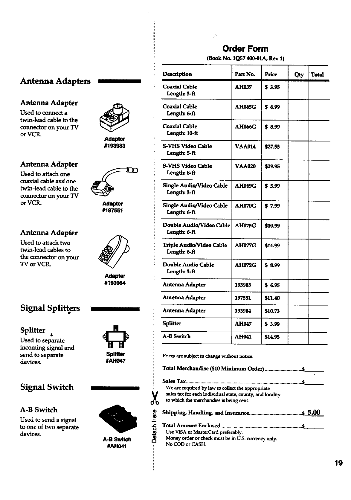
Antenna Adapters
Antenna Adapter
Used to connect a
twin-lead cable to the
connector on your TV
or VCR.
Antenna Adapter
Used to attach one
coaxial cable and one
twin-lead cable to the
connector on your TV
or VCR.
Antenna Adapter
Used to attach two
twin-lead cables to
the connector on your
TV or VCR.
Signal Splitters
Splitter •
Used to separate
incoming signal and
send to separate
devices.
Signal Switch
A-B Switch
Used to send asignal
to one of two separate
devices.
@
adap_r
#193963
Adapter
#197551
Adapter
#193984
Splitter
#AH047
A-B Switch
#AH041
Order Form
(Book No. 1Q57 400-01A, Rev 1)
Description
Coaxial Cable
Length: 3-ft
Coaxial Cable
Length: 6-ft
Coazial Cable
Length: 10-ft
S-VHS Video Cable
Length: 5-ft
S-VHS Video Cable
Length: 8-ft
Single Audio/Video Cable
Length: 3-fl
Single Audio/Video Cable
Length: 6-ft
Double Audio/Video Cable
Length: 6-fl
Triple Audio/Video Cable
Length: 6-ft
Double Audio Cable
Length: 3-ft
Antenna Adapter
Antenna Adapter
Antenna Adapter
SpUtter
A-B Switch
Part No.
AH037
AH065G
AH066G
VAA014
VAA020
AH069G
AH070G
AH075G
AH077G
AH072G
193983
197551
193984
AH047
AH041
$s.gs
$27.55
$29.95
$5.99
$7.99
$I0.99
$24.99
$ 8.99
$6.95
521.4o
51o.75
153.99
514.95
Qty Total
Prices are subject to change without notice.
Total Merchandise (520 Minimum Order) ...............................___
Sales Tax .................................................................................................___
We are required by law to collect the appropriate
sales tax for each individual state, county, and locality
to which the merchandise is being sent.
Shipping, Handling, and Insurance ........................................... .$ 5.00
T
.C Total Amount Enclosed ................................................................... &__
_Use VISA or M_erCard preferably.
Money order or check must be in U.S. currency only.
£3 No COD or CASH.
19
20
(_g eyore orderon your VISA
or MastetCardby .
filling in below
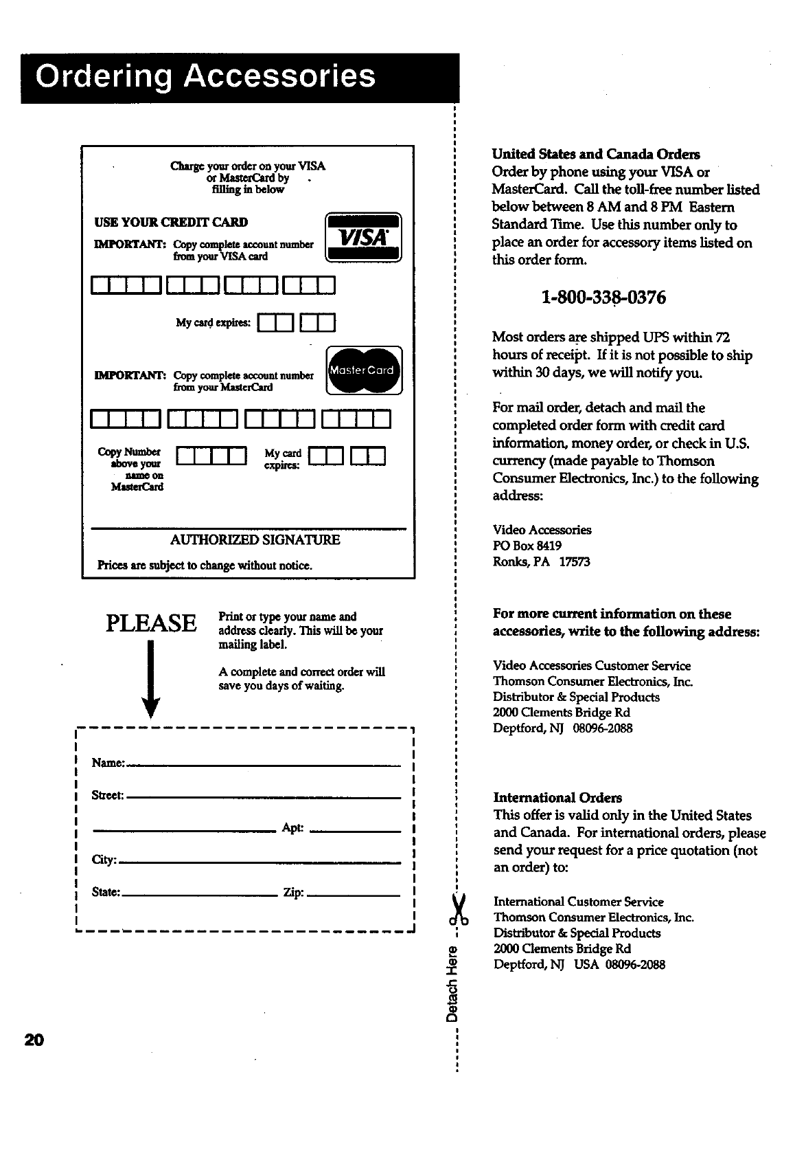
USE YOUR CREDIT
IMIN)RTANT: Copy completeaccountnumber
f_omyourVISA cmd
VISA"
IMPORTANT:. Copy completeaccountnumber
_e_ yourMute_
I-I-I-T-If I I I II I I I''11 1 1 1 1
o_._ I-TTq'q
aboveyour
nllme on
Ivlaste_ard
rTn rnn
¢xpn_;:
AUTHORIZED SIGNATURE
Prices a_esubjectto change withoutnotice.
PLEASE
!Print or type your name and
address dearly. This will be your
mailing label.
A complete and correct orderwill
save you days of waiting.
Name_
Street:
City:
State_
Apt:
Zip:
-1-
.C
United States and Canada Orders
Order by phone using your VISA or
MasterCard. Call the toll-fzee number listed
below between 8 AM and 8 PM Eastern
Standard Tune. Use this number only to
place an order for accessory items listed on
this order form.
1-800-338-0376
Most orders _shipped UPS within 72
hours of receipt. If it is not possible to ship
within 30 days, we will notify you.
For mail order, detach and mail the
completed order form with credit card
information, money order, or check in U.S.
currency (made payable to Thomson
Consumer Electronics, Inc.) to the following
address:
Video Accessories
PO Box 8419
Ronks, PA 17573
For more current information on these
accessories, write to the following address:
Video Accessories Customer Service
Thomson Consumer Einctxonics, Inc.
Distributor & Special Products
2000 Clements Bridge Rd
Deptford, NJ 08096-2088
International Orders
This offer is valid only in the United States
and Canada. For international orders, please
send your request for a price quotation (not
an order) to:
International Customer Service
Thomson Consuraer Elect_nics, Inc.
Distributor & Special Products
2000 Clements Bridge Rd
Depfford, NJ USA 0_096-2088
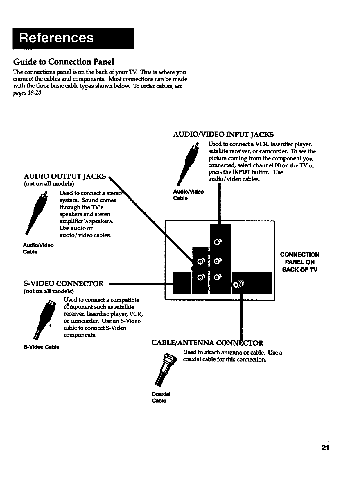
Guide to Connection Panel
The connections panel is on the back of your T_. This is where you
connect the cables and components. Most connections can be made
with the three basic cable types shown below. To order cables, see
pages 18-20.
AUDIO OUTPUT JACKS.
(not on all models)
/system. Sound comes
through the TV's
speakers and stereo
amplifier'sspeakers.
Use audio or
audio/video cables.
Audio/Video
Cable
S-VIDEO CONNECTOR
(not on all models)
fUsed to connect a compatible
c_mponent such as satellite
receiver, laserdisc playe_ VCR,
or camcorder. Use an S-Video
cable to connect S-Video
components.
S-Video Cable
AUDIO/VIDEO INPUT JACKS
/
AudioNIdeo
Cable
Used to connect a VCK laserdisc playe_
satellite l_ceiver, or camcorder. To see the
picture coming from the component you
connected, select channel 00 on the TV or
press the INPUTbutton* Use
audio/video cables.
CONNECTION
PANEL ON
BACK OF TV
CABLE/ANTENNA CONNECTOR
Used to attach antenna or cable. Use a
coaxial cable for this connection.
Coaxial
Cable
21
Thlngs to Know Before Connecting Cables
Protect your components from
power surges
•Connect all components before plugging any power cords into the
wall outlet.
• Always turn off the TV and/or component before you connect or
disconnect any cables.
Avoid audio hum or interference by
positioning cables correctly
Insert all cable plugs firmly into their jacks.
Place the audio/video cables to the sides of the TV's back panel
instead of straight down the middle after you connect your
components.
Try not to coil any twin-lead cables and keep them away from the
audio/video cables as much as possible.
Make sureallantennasand cablesareproperlygrounded. Referto
theSafetyTipssheetpacked with your TV.
Protect your components from
overheating
•Do not block ventilation holes in any of the components. Arrange
the components so that air can circulate freely.
• Do not stack components.
- Allow adequate ventilation when placing your components in a
stand.
•Place an amplifier on the top shelf of the stand so heated air rising
from it win not flow around other components.
Connect audio/video cables for best
results • Required for picture-in-picture feature (this feature is not on all
models).
22
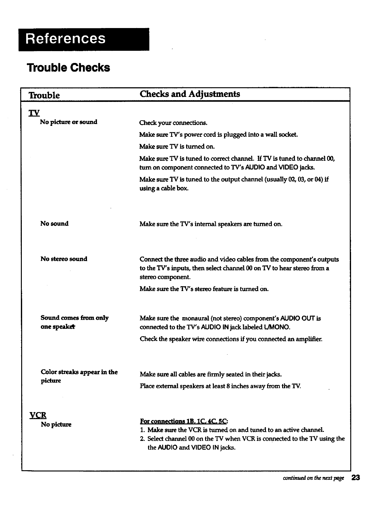
Trouble Checks
Trouble
TV
No picture or sound
Checks and Adjustments
Check your connections.
Make sure TV's power cord is plugged into a wall socket.
Make sure TV is turned on.
Make sure TV is tuned to correct channeL If TV is tuned to channel 00,
turn on component connected to TV's AUDIO and VIDEO jacks.
Make sure TV is tuned to the output channel (usually 02, 03, or 04) if
using a cable box.
No sound Make sure the TV's internal speakers are turned on.
No stereo sound Connect the three audio and video cables from the component's outputs
to the TV's inputs, then select channel 00 on TV to hear ste_o from a
stereo component.
Make sure the TV's stereo feature is turned on.
Sound comes from only
one speak_
Make sure the monaural (not stereo) component's AUDIO OUT is
connected to the TV's AUDIO IN jack labeled IJMONO.
Check the speaker wire connections if you connected an amplifier.
Color streaks appear in the
picture Make sure all cables are firmly seated in their jacks.
Place external speakers at least 8 inches away from the TV.
VCR
No picture For connections lB. 1C. 4C. f,C:
1. Make sure the VCR is turned on and tuned to an active channeL
2. Select channel 00 on the TV when VCR is connected to the TV using the
the AUDIO and VIDEO IN jacks.
conanuedon thenextpage 23
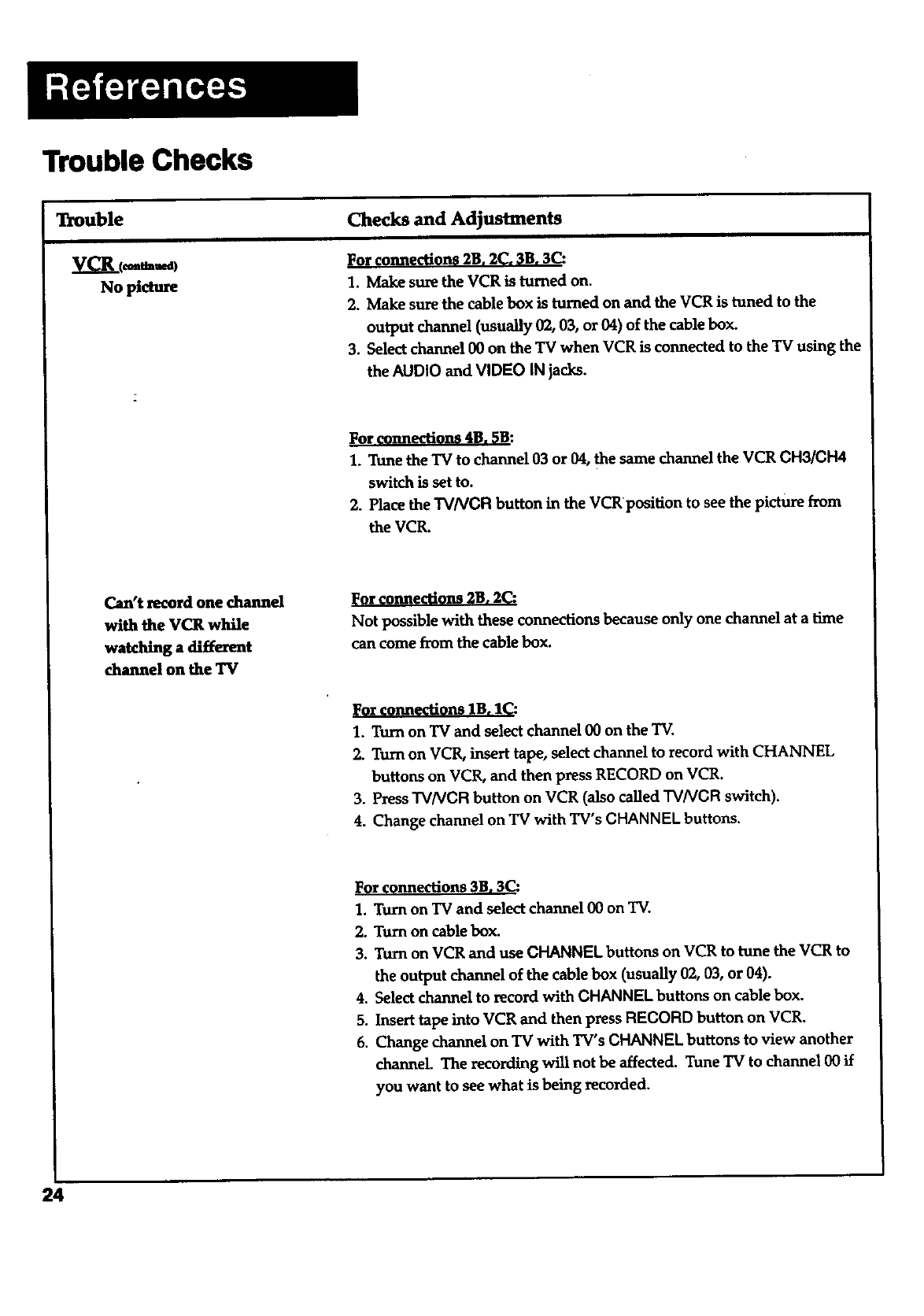
Trouble Checks
Trouble
No picture
Checks and Adjustments
For connections 2B. 2C, 3B. 3C:
1. Make sure the VCR is turned on.
2. Make sure the cable box is turned on and the VCR is tuned to the
output channel (usually 02, 03, or 04) of the cable box.
3. Select channel 00 on the TV when VCR is connected to the TV using the
the AUDIO and VIDEO IN jacks.
For connecti@ns 4B. 5B:
1. Tune the TV to channel 03 or 04, the same channel the VCR CHS/CH4
switch is set to.
2. Place the TVNCR button in the VCRpositian to see the picture from
the VCR.
Can't record one channel
with the VCR while
watching a different
channel on the TV
l_or connections 2B. 2C:
Not possible with these connections because only one channel at a time
can come from the cable box.
]_or connections lB. I_:
1. Turn on TV and select channel 00 on the TV.
2. Turn on VCR, insert tape, select channel to record with CHANNEL
buttons on VCR, and then press RECORD on VCR.
3. Press TVNCR button on VCR (also called TVNCR switch).
4. Change channel on TV with TV's CHANNEL buttons.
]Forconnections 3B. 3C:
1. Turn on TV and select channel 00 on TV.
2. Turn on cable box.
3. Turn on VCR and use CHANNEL buttons on VCR to tune the VCR to
the output channel of the cable box (usually 02, 03, or 04).
4. Select channel to record with CHANNEL buttons on cable box.
5. Insert tape into VCR and then press RECORD button on VCR.
6. Change channel on TV with TV's CHANNEL buttons to view another
channel. The recording will not be affected. Tune TV to channel 00 if
you want to see what is being recorded.
24
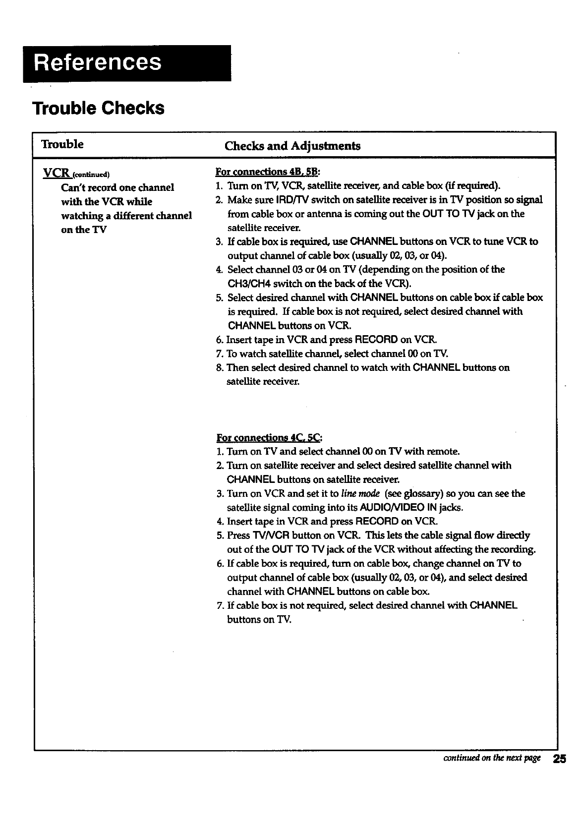
Trouble Checks
Trouble
VCR ((onfiatued)
Can't record one channel
with the VCR while
watching a different channel
on the TV
Checks and Adjustments
For connections 4B. 5B:
1. Turn on TV, VCR, satellite receiver, and cable box (if required).
2. Make sure IRD[I'V switch on satellite receiver is in "IV position so signal
from cable box or antenna is coming out the OUT TO "IVjack on the
satellite receiver.
3. If cable box is required, use CHANNEL buttons on VCR to tune VCR to
output channel of cable box (usually 02, 03, or 04).
4. Select channel 03 or 04 on TV (depending on the position of the
CH3/CH4 switch on the back of the VCR).
5. Select desired channel with CHANNEL buttons on cable box if cable box
is required. If cable box is not required, select desired channel with
CHANNEL buttons on VCR.
6. Insert tape in VCR and press RECORD on VCR.
7. To watch satellite channel, select channel 00 on TV.
8. Then select desired channel to watch with CHANNEL buttons on
satellite receiver.
For connections 4Co 5C:
1. Turn on TV and select channel 00 on TV with remote.
2. Turn on satellite receiver and select desired satellite channel with
CHANNEL buttons on satellite receiver.
3. Turn on VCR and set it to line mode (see glossary) so you can see the
satellite signal coming into its AUDIONIDEO IN jacks.
4. Insert tape in VCR and pressRECORD on VCR.
5. PressTVNCR button on VCR. This lets the cable signal flow directly
out of the OUT TO TV jack of the VCR without affecting the recording.
6. If cable box is required, turn on cable box, change channel on TV to
output channel of cable box (usually 02, 03, or 04), and select desired
channel with CHANNEL buttons on cable box.
7. If cable box is not required, select desired channel with CHANNEL
buttons on TV.
continued on the next page 25
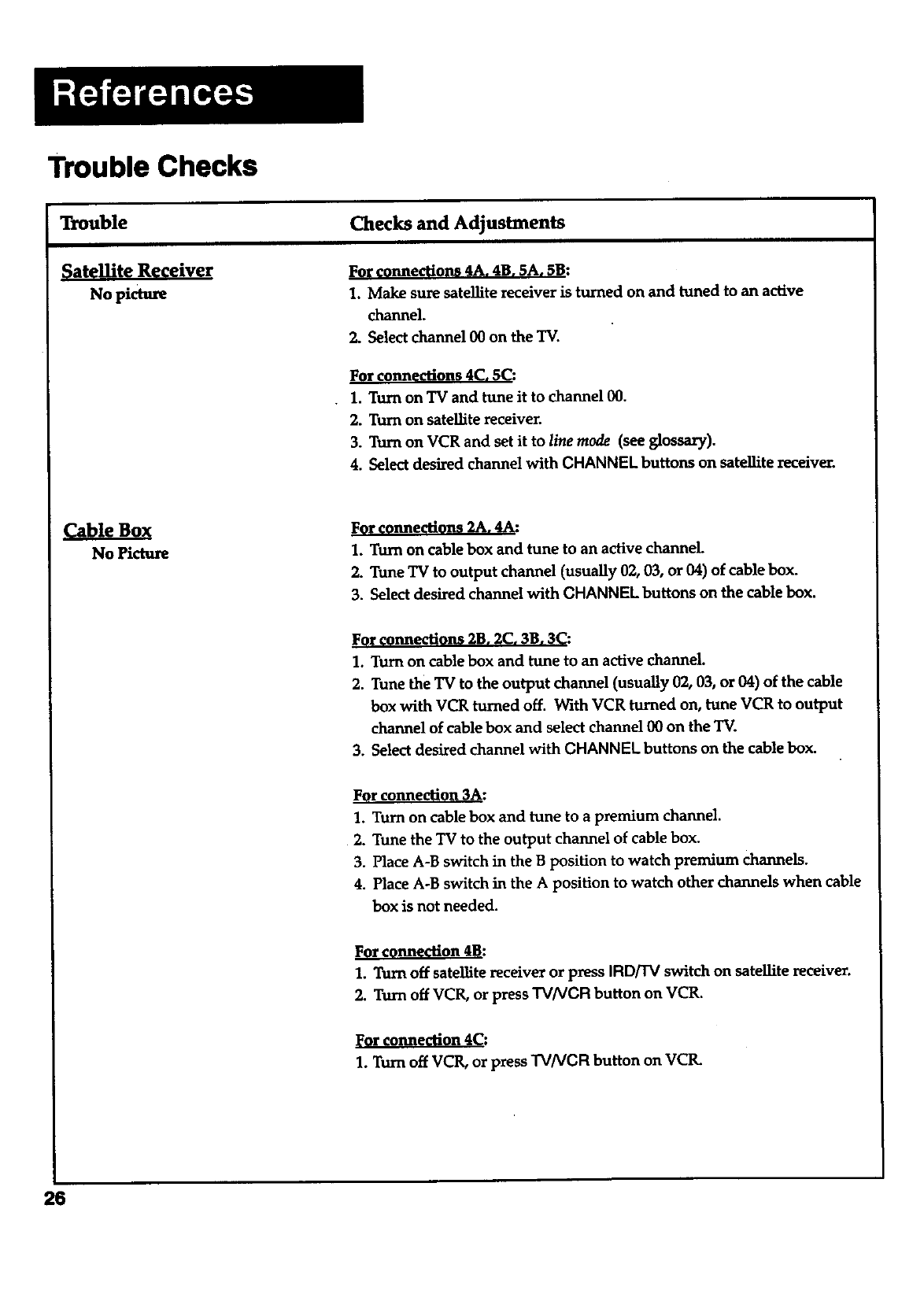
Trouble Checks
Trouble
Nopiaure
Checks and Adjustments
FOr connections 4A. 4B. 5A, 5B:
1. Make sure satellite receiver is turned on and tuned to an active
channel.
2. Select channel 00 on the TV.
For connections 4C. 5C:
1. Turn on "IVand tune it to channel 00.
2. Turn on sateUite receiver.
3. Turn on VCR and set it to line mode (see glossary).
4. Select desired channel with CHANNEL buttons on satellite receiver.
Cable Box
No Picture
Fnne'n 2A :
1. Turn on cable box and tune to an active channel.
2. Tune TV to output channel (usually 02, 03, or 04) of cable box.
3. Select desired channel with CHANNEL buttons on the cable box.
For connections 2B. 2C. 3B, 3C:
1. Turn on cable box and tune to an active channeL
2. Tune the TV to the output channel (usually 02, 03, or 04) of the cable
box with VCR turned off. With VCR turned on, tune VCR to output
channel of cable box and select channel 00 on the TV.
3. Select desired channel with CHANNEL buttons on the cable box.
For connection 3A:
1. Turn on cable box and tune to a premium channel.
2. Tune the TV to the output channel of cable box.
3. Place A-B switch in the B position to watch premium channels.
4. Place A-B switch in the A position to watch other channels when cable
box is not needed.
For connection 4B:
1. Turn off satellite receiver or press IRD/TV switch on satellite receiver.
2. Turn off VCR, or press "rv/VCR button on VCR.
lForconnection 4(=."
1. Turn off VCR, or press "rv/VCR button on VCIL
26
Trouble Checks
Trouble
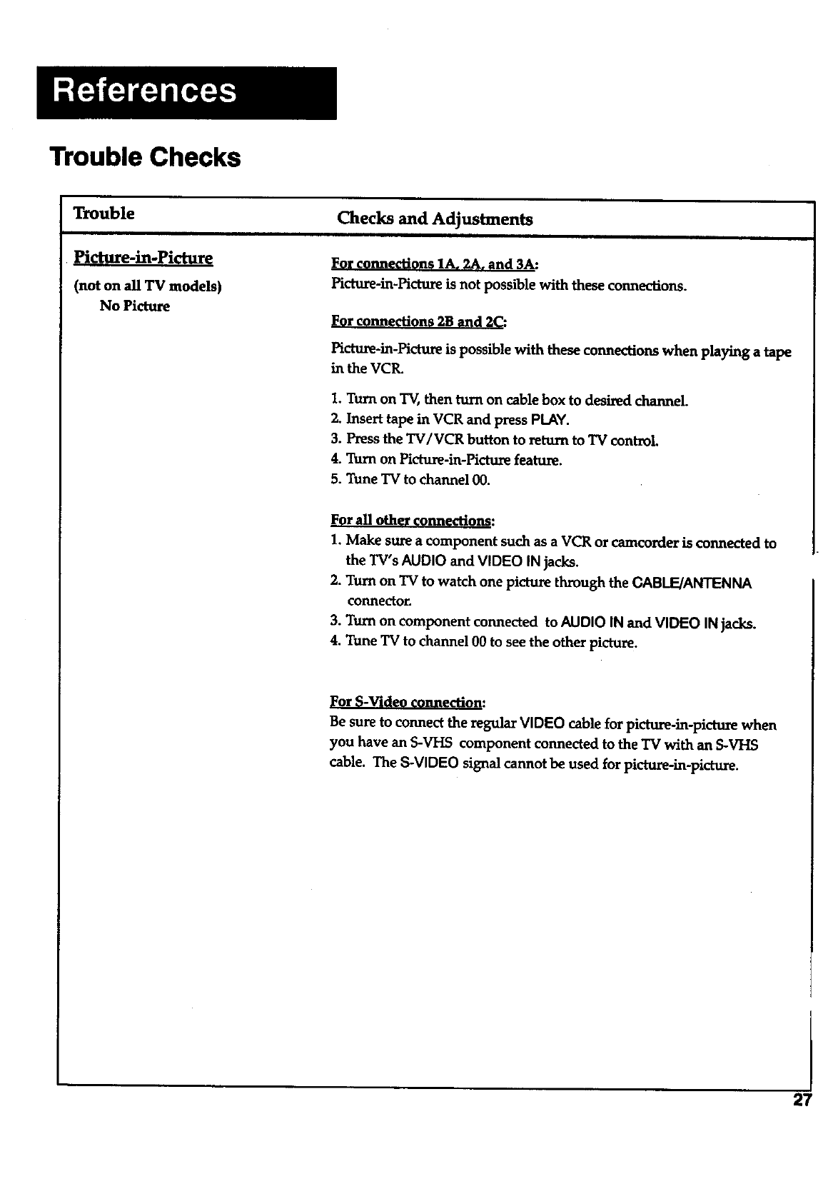
Pictttre-in-Picture
(not on all TV models)
No Picture
Checks and Adjustments
For connections 1A, 2A, and 3A:
Picture-in-Picture is not possible with these connections.
For connections 2B and 2C:
Pictm_-in-Picture is possible with these connections when playing a tape
in the VCR.
1. Turn on TV, then turn on cable box to desired channel.
2. Insert tape in VCR and press PLAY.
3. Press the TV/VCR button to return to TV control
4. Turn on Picture-in-Picture feature.
5. Tune TV to channel 00.
F r all oth nn "ons:
1. Make sure a component such as a VCR or camcorder is connected to
the TV's AUDIO and VIDEO IN jacks.
2. Turn on TV to watch one picture through the CABLE/ANTENNA
connector.
3. Turn on component connected to AUDIO IN and VIDEO IN jacks.
4. Tune TV to channel 00 to seethe other picture.
r -V" "on:
Be sure to connect the regular VIDEO cable for picture-in-picture when
you have an S-VHS component connected to the TV with an S-VHS
cable. The S-VIDEO signal cannot be used for picture-in-picture.
27
Glossary
28
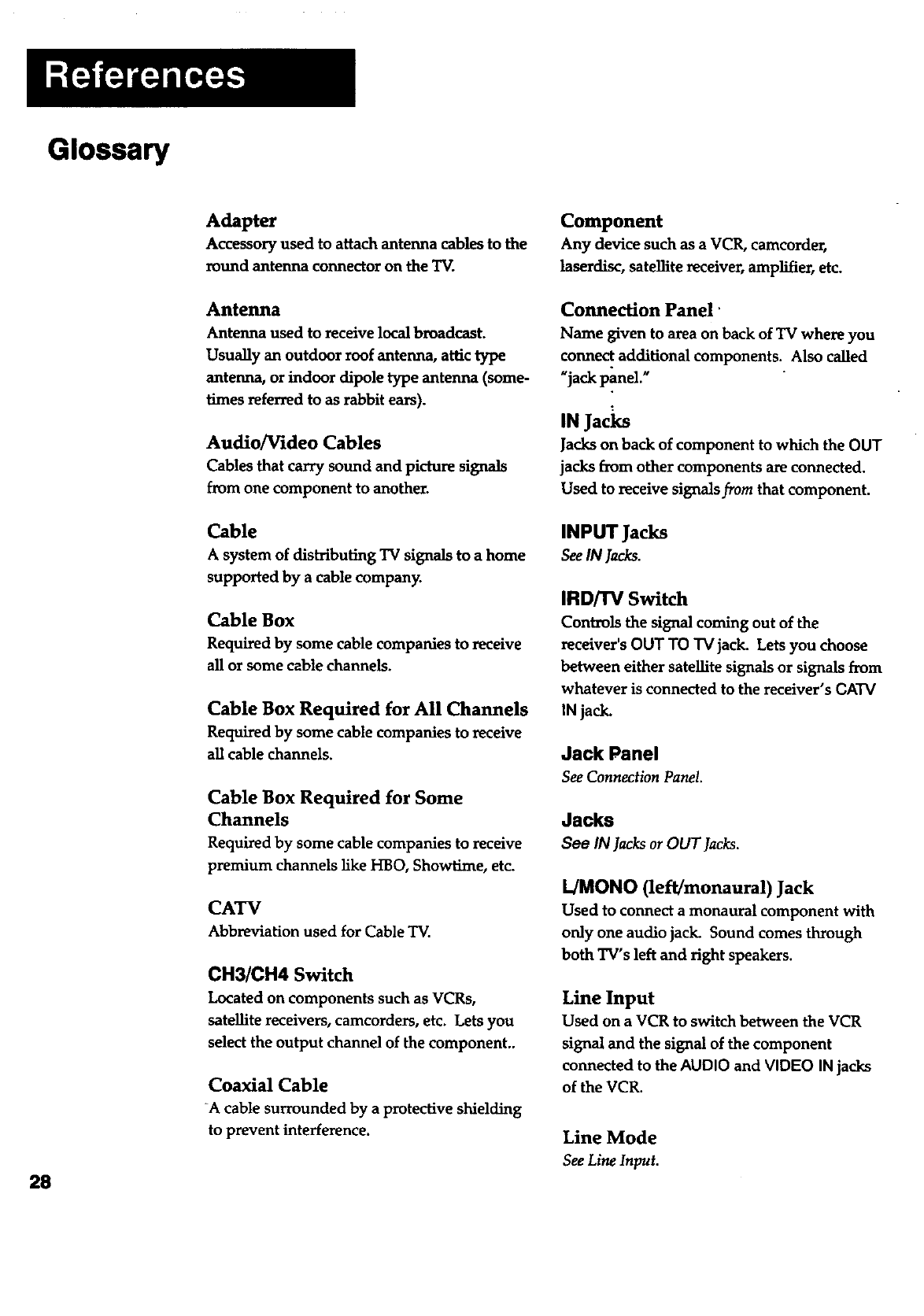
Adapter
Accessory used to attach antenna cables to the
round antenna connector on the "IV.
Antenna
Antenna used to receive local broadcast.
Usually an outdoor roof antenna, attic type
antenna, or indoor dipole type antenna (some-
l_aes referred to as rabbit ears).
Audio/Video Cables
Cables that carry sound and picture signals
from one component to another.
Cable
A system of distributing TV signals to a home
supported by a cable compan_
Cable Box
Required by some cable companies to receive
all or some cable channels.
Cable Box Required for All Channels
Required by some cable companies to receive
all cable channels.
Cable Box Required for Some
Channels
Required by some cable companies to receive
premium channels like HBO, Showtime, etc.
CATV
Abbreviation used for Cable TV.
CH3/CH4 Switch
Located on components such as VCRs,
satellite receivers, camcorders, etc. Lets you
select the output channel of the component..
Coaxial Cable
-A cable surrounded by a protective shielding
to prevent interference.
Component
Any device such as a VCR, camcorder,
lasardisc, satellite receiver, amplifier, etc.
Connection Panel'
Name given to area on back of TV where you
connect additional components. Also called
Ujack panel."
IN Jacl<s
Jacks on back of component to which the OUT
jacks from other components are connected.
Used to receive signals from that component.
INPUT Jacks
SeeIN Jacks.
IRD/'I'V Switch
Controls the signal coming out of the
receiver's OUT TO TV jack. Lets you choose
between either satellite signals or signals from
whatever is connected to the receiver's CATV
IN jack.
Jack Panel
SeeConnectionPanel.
Jacks
See IN lacks or OUT Jacks.
L/MONO (left/monaural) Jack
Used to connect a monaural component with
only one audio jack. Sound comes through
both TV's left and right speakers.
Line Input
Used on a VCR to switch between the VCR
signal and the signal of the component
connected to the AUDIO and VIDEO IN jacks
of the VCR.
Line Mode
SeeLineInput.
Glossary
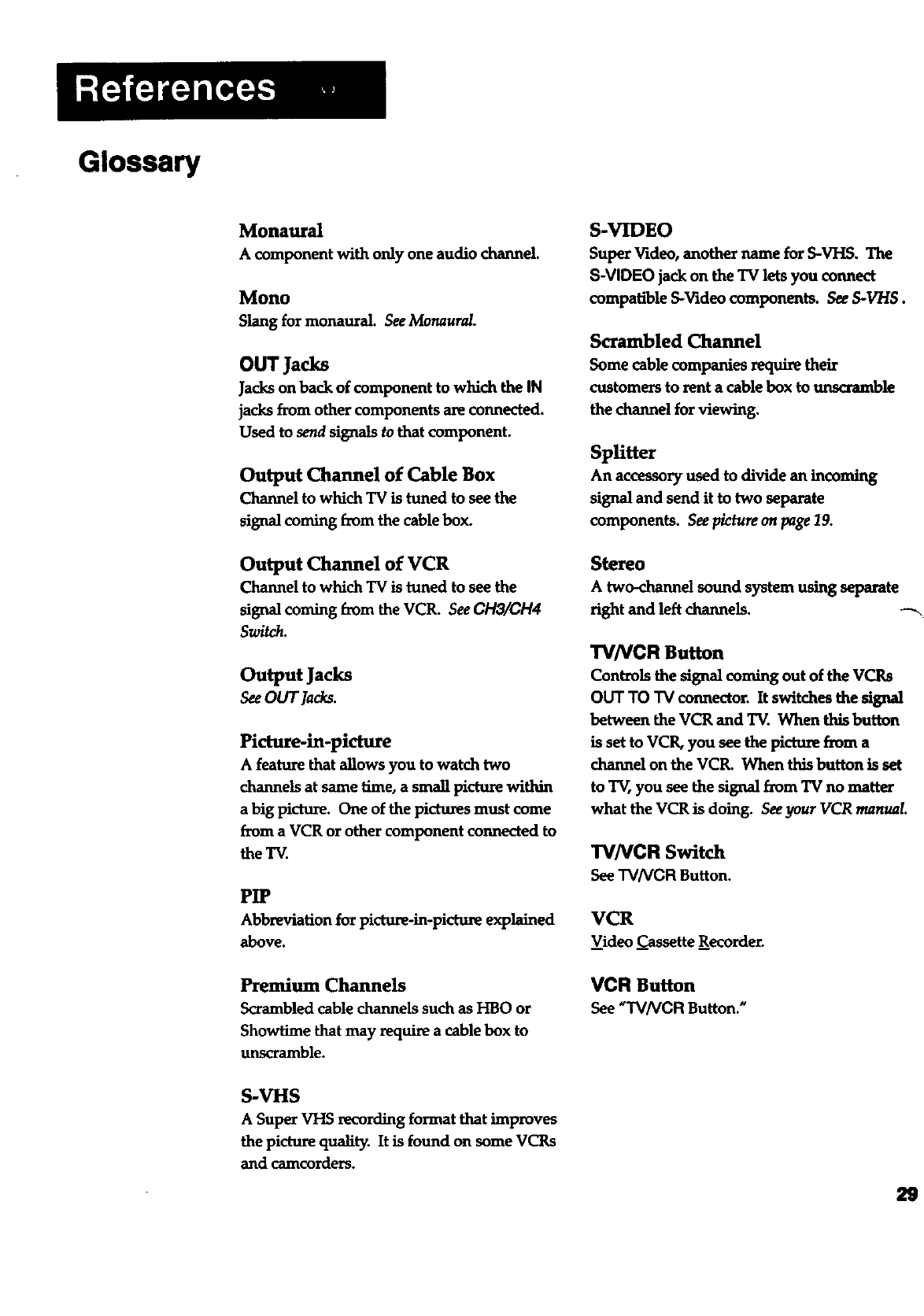
Monaural
A component with only one audio channel.
Mono
Slang for monaural. See Monaurcd.
OUT Jacks
Jacks on back of component to which the IN
jacks from other components are connected.
Used to send signals to that component.
Output Channel of Cable Box
Channel to which TV is tuned to see the
signal coming from the cable box.
Output Channel of VCR
Channel to which TV is tuned to see the
signal coming from the VCR. See CH3/CH4
Switch.
Output Jacks
SeeOUT Jacks.
Picture-in-picture
A feature that allows you to watch two
channels at same time, a small picture within
a big picture. One of the pictures must come
from a VCR or other component connected to
the TV.
PIP
Abbreviationforpicture-in-pictureexplained
above.
Premium Channels
Scrambled cable channels such as I-IBOor
Showtime that may require a cable box to
unscramble.
S-VHS
ASuper VHS xecording format that improves
the picture quality. It is found on some VCRs
and camcorders.
S-VIDEO
Super Video, another name for S-VHS. The
S-VIDEO jack on the "IV lets you connect
compatible S-Video components. See S-V/'/S.
Scrambled Channel
Some cable companies require their
customers to rent a cable box to unscramble
the channel for viewing.
SpUtter
An accessoryused to dividean incoming
signaland send ittotwo separate
components. Seepictureon page19.
Stereo
Atwo-channelsound system usingseparate
right and left channels. _-_
TVNCR Button
Controls the signal coming out of the VCRs
OUT TO TV connector. It switches the signal
between the VCR and TV. When this button
is set to VCR, you see the picture fnnn a
channelon theVCR. When thisbuttonisset
toTV,you seethesignalfrom TV no matter
what theVCR isdoing.SeeyourVCR manual.
TVNCR Switch
SeeTVNCR Button.
VCR
Video Cassette Recorder.
VCR Button
See"TVNCR Button."
29
If your TV needs service, please refer to the warranty in the TV User's
Guide. Please do not send any products to the indianapolis address
listed in this manual or on the carton. This will only add delays in
service for your product.
Thomson Consumer Electronics
600 N Sherman D_ PO Box 1976
indianapolis, IN46206-1976
FL68690
©1994 Thomson Consumer Electronics, Inc.
Trademark(s)@ Registered
Marca(s) Re_trada(s)
Printed in the U.S.A.
Part Number 1Q57400-01A, Rev I
