RCI 9212i LW Stand Alone Keypads Installation Instructions Is9212ilw R1113
User Manual: RCI 9212iLW Stand Alone Keypads Installation Instructions Installation Instructions
Open the PDF directly: View PDF ![]() .
.
Page Count: 6
IS9212iLW
Features:
• FlushMount,SingleGang
•IlluminatedBacklitKeys
•KeypadProgrammable
• KeypressFeedbackviaBuilt-InSounder
•Bi-ColorRed/GreenLEDIndicatesRelayStatus
•YellowLEDIndicatesProgramMode
•120Users
•SingleUseCodes
•LockoutUsers
•Passage/ToggleCodes
•10to30VoltDCOperation
•12to24VoltACOperation
•2AmpMainRelay
•RemoteTriggerInput(REX)
• 2YearWarranty
Product Description:
The212iLWkeypadfeaturesasingle-relayoutputtocontrolany
devicerequiringanon/offswitch.Theoutputistimedorlatchedand
operatedbyauser’sPINcode.Additionally,the212iLWkeypad
providesbasickeylessentrybycontrollingadoorlockingdevice
wheresecurityisnotanissue.
The212iLWstylekeypadsaredesignedforbothindoorandoutdoorush
mountapplications.Theelectronicsareconformalcoatedinthe
manufacturingprocessinordertoprovidethislevelofapplication
exibility.Inaddition,eachkeypaduseshardenedkeystoassurelong-term,
high-qualityperformance.
Eachkeypadcontainsilluminatedclearkeysthatmakeoperationinlow
lightsituationseasyandaccurate.iLWstylekeypadsmounttoanystandard
single-gangelectricalboxordirectlytoanywall.
Specifications:
Parameter Range/Description
Voltage 10–30VDC,12-24VAC(Auto-Adjusting)
Current 93mA@10VDC;158mA@30VDC,148mA@12VAC;198mA@24VAC
Environment ForIndoorandOutdoorUse
TemperatureTolerance -20°Fto130°F(-28°Cto54°C)
Dimensions 51/8”Hx33/8”Wx5/8”D
MainRelay(FormC) ContactRating:2A@30VAC/DC
REXInput NormallyOpenDryContact
DoorPositionInput NormallyClosedDryContact
LEDs Bi-ColorRed/Green;Yellow
Default Keypad Settings
Parameter Default Setting
MasterCode 1234
LockOutput Relay1(Mainrelay)
AudioAlerts Notassigned
REX TriggersLockOutput
REXOperation AlwaysTriggers(regardlessofDoorLoop)
ErrorLockout/Threshold Enabled/3Attempts
ErrorLockoutDuration 10seconds
LockOutputTime 5seconds
Visual/AudioKeypressFeedback Enabled
Auto-Entry Disabled
UserLockout Enabled
PCN13023
R11/13CA
INSTALLATION 9212iLW
Interior/Exterior Use Stand-Alone Keypad
©2013 RutheRfoRd contRols • www.RutheRfoRdcontRols.com
usA: 2517 sQuAdRon couRt, suIte 104, VIRGInIA BeAch, VA 23453 • cAnAdA: 210 sheARson cRescent, cAmBRIdGe, on n1t 1j6
Phone • 1.800.265.6630 • 519.621.7651 • fAX: 1.800.482.9795 • 519.621.7939 • e-mAIl: sAles@RutheRfoRdcontRols.com
9212iLW Keypad Installation Instructions (Continued)
©2013 RutheRfoRd contRols • www.RutheRfoRdcontRols.com
usA: 2517 sQuAdRon couRt, suIte 104, VIRGInIA BeAch, VA 23453 • cAnAdA: 210 sheARson cRescent, cAmBRIdGe, on n1t 1j6
Phone • 1.800.265.6630 • 519.621.7651 • fAX: 1.800.482.9795 • 519.621.7939 • e-mAIl: sAles@RutheRfoRdcontRols.com
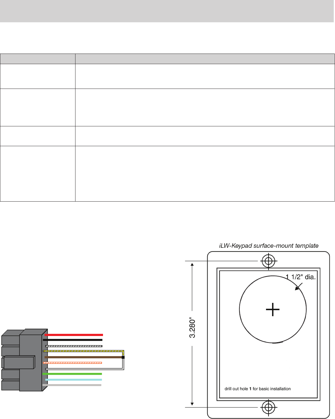
MOUNTING
Thekeypadisdesignedtobeushmountedusingastandardsinglegangelectrical
box.Inaddition,itcanbeushmounteddirectlytothewallsurfacebycuttingahole
inthewall.Toproperlysizethemountingandwireaccesshole,usetheinstallation
templateonthelastpageinthismanual.
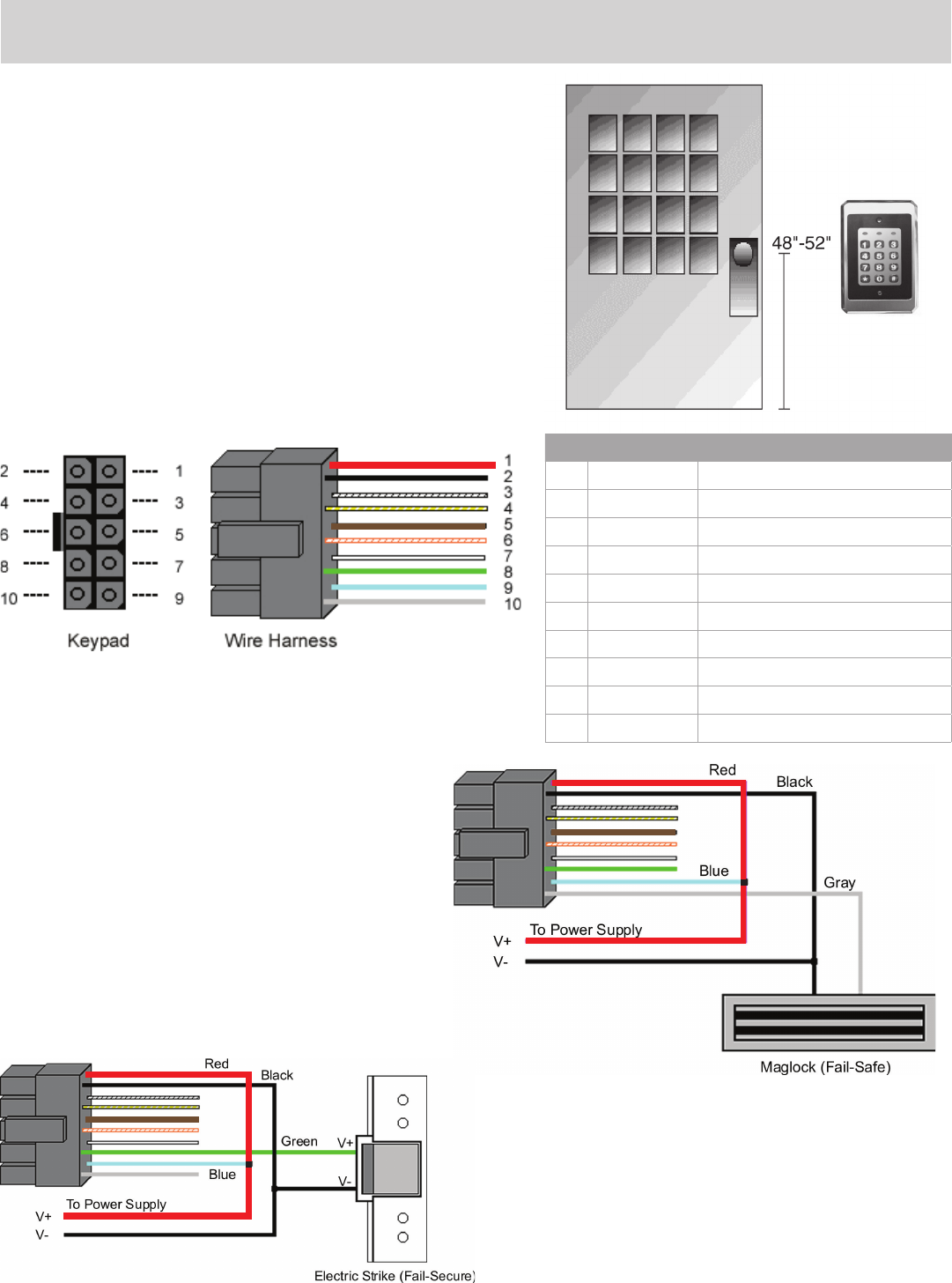
Mountingheightcanvarydependingonrequirements.Anappropriaterangeis
typicallybetween48and52inchesoncenterofftheoor.
Foroutdoorinstallations,useaweatherproofbackboxandsealthewireentrylocations
withsiliconeandprovideadrainhole.Inaddition,usetheanti-oxidantgreasepackfor
thewireharnessconnectors. Figure 1 Keypad
MountingHeight
WIRING : Wire Harness Configuration
Figure 2 Keypad Connector
and Wire Harness
Pin Wire Color Signal name
1 Red V+(KeypadPower)
2 Black V-(KeypadPower)
3 White/Black NotUsed
4 White/Yellow NotUsed
5 Brown RemoteTrigger(REX)
6White/Orange LoopCommon(REXandDoorLoop)
7White DoorLoopMonitor
8 Green MainRelay–NormallyOpen
9Blue MainRelay-Common
10 Gray MainRelay–NormallyClosed
Wiring the Keypad to a Maglock (Fail-Safe)
UsethefollowingstepstoconnectthekeypadtoaMaglock
(Fail-Safe):
1.Connecttheredwire(V+)tothebluewire(common),andthen
connectthemtothepositiveonthepowersupply.
2.Connectthegraywire(normallyclosed)tothepositiveonthe
Maglock.
3.Connecttheblackwire(V-)tothenegativeontheMaglock,and
thenconnectthemtothenegativeonthepowersupply.
Figure 3 WiringtheKeypadtoa
Maglock(Fail-Safe)
Wiring the Keypad to an Electric Strike (Fail-Secure)
Usethefollowingstepstoconnectthekeypadtoanelectricstrike
(fail-secure)(seeFigure4forreference):
1. Connecttheredwire(V+)tothebluewire(common),andthen
connectthemtothepositiveonthepowersupply.
2. Connectthegreenwire(normallyopen)tothepositiveonthe
strike.
3. Connecttheblackwire(V-)tothenegativeonthestrike,and
thenconnectthemtothenegativeonthepowersupply.
Figure 4 WiringtheKeypadtoan
ElectricStrike(Fail-Secure)
9212iLW Keypad Installation Instructions (Continued)
©2013 RutheRfoRd contRols • www.RutheRfoRdcontRols.com
usA: 2517 sQuAdRon couRt, suIte 104, VIRGInIA BeAch, VA 23453 • cAnAdA: 210 sheARson cRescent, cAmBRIdGe, on n1t 1j6
Phone • 1.800.265.6630 • 519.621.7651 • fAX: 1.800.482.9795 • 519.621.7939 • e-mAIl: sAles@RutheRfoRdcontRols.com
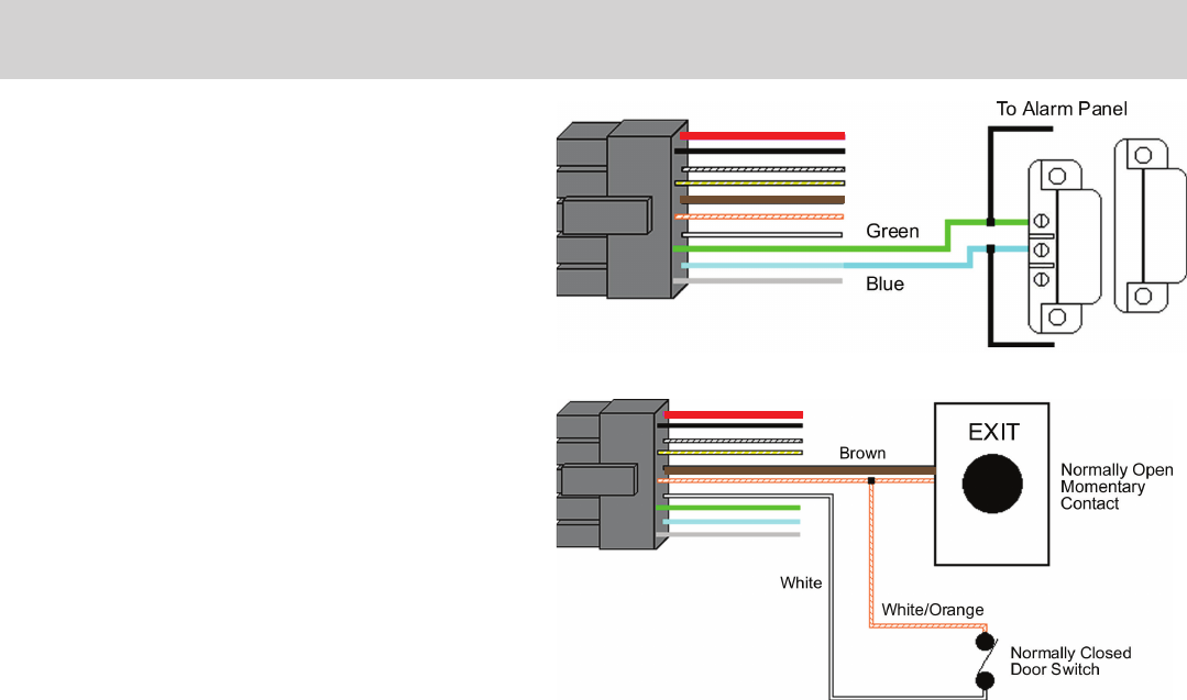
Shunting a Normally Closed Zone
Usethefollowingstepstousethekeypadtoshuntanormallyclosed
zone:
1.Connectthebluewire(common)tothecommonconnectionon
thedoorpositionswitch.
2.Connectthegreenwire(normallyopen)tothenormallyclosed
connectiononthedoorpositionswitch.
Figure 5: Shunting a Normally Closed Zone
Wiring Remote Trigger as Request to Exit (REX)
Button and Door Contacts
Use the following steps to connect the keypad to a normally
open REX device and normally closed door switch:
1. Connect the brown wire (REX Input) to the normally
open connection on the REX device.
2. Connect the white/orange (loop common) to the
common on the REX device and the common on the
door switch.
3. Connect the white wire (door loop) to the normally
closed connection on the door switch.
NOTE: Doorloopdoesn’tneedtobeclosedfortheREXfunctiontooperate,by
default,butsettingoption8to0undercommand30,programstheREXfunctionto
operateonlywhenthedoorloopisclosed.ThispreventstheREXfromre-triggering
whenthedoorisopen
Figure 6: Wiring a REX Button
and Door Contacts
TESTING THE KEYPAD
After installing the keypad, RCI recommends that you perform the keypad self-test once a year, to ensure that the keypad works properly.
1. To perform the self-test, with the unit powered up, press the following keys on the keypad: 7890#123456*
•Ifall12keypressesareaccepted,thekeypadentersself-testmode.
•TheLEDsalternategreen,yellow,andredfollowedbythesounderbeepingthreetimes.
2. Verify that the master code works correctly. (The master code accesses program mode and activates the main relay to verify that
the locking device is working.)
The default master code is 1234. (If the default is not working, refertoWIREHARNESSLOOPBACKCONNECTIONSsectiononpg.6)
PROGRAMMING
Toenterprogrammode,press99#MasterCode*.TheyellowLEDmustthenstartblinkingslowing(ifnotverifythemastercodeis
correct–refertoWIREHARNESSLOOPBACKCONNECTIONSsection).ThedefaultMasterCodeis1234.
NOTE: If auto-entry is enabled, the * (asterisk) key is not used to enter Program mode. To change the Master Code, enter:
1 # new Master Code * new Master Code * (When finished press the * to exit program mode.)
Note: RefertoPROGRAMMINGUSERSsectiononpg.4foraddingusercodes
A record of all user locations must be maintained to effectively manage keypad and maintain proper security of site. A sample form is
available for download at www.rutherfordcontrols.com - Support - Keypads & Readers section.
To Alarm Panel

9212iLW Keypad Installation Instructions (Continued)
©2013 RutheRfoRd contRols • www.RutheRfoRdcontRols.com
usA: 2517 sQuAdRon couRt, suIte 104, VIRGInIA BeAch, VA 23453 • cAnAdA: 210 sheARson cRescent, cAmBRIdGe, on n1t 1j6
Phone • 1.800.265.6630 • 519.621.7651 • fAX: 1.800.482.9795 • 519.621.7939 • e-mAIl: sAles@RutheRfoRdcontRols.com
PROGRAMMING USERS
To enter program mode press 99 # master code *.
Command/Action Keys to Enter/Details
MasterCode User#1isthemastercode;itcanaccessallcommandsinprogrammode.Thedefaultcodeis1234.Themastercode
canbeprogrammedwith60asastandarduseronly.
SupervisorCode
User#2,whenprogrammed,isthesupervisorcode.Thesupervisorcanaccessprogrammode,butislimitedto
addinganddeletingusers,aswellasenablingordisablingusers.Thesupervisorcodecan’tchange,delete,ordisable
themastercodeorsupervisorcodeitself.
AddStandardUser (shortversion)userlocation#code*code*
AddUserwithSpecicUnlock
Time
unlocktime#userlocation#code*code*(Thiscommandisusedtoprogramauserwithaspecicunlocktime.
Thisuseractivatesthevirtuallockoutput.)
DeleteUser userlocation#**
Command 60.
Add/ModifyEnhancedUser
60 # user type # user location # code * code *
(codescanbefrom1to10digitsinlength)
User Types
0–ToggleUser
1–StandardUser
3–LockoutUser
5–SingleUseCode
7–EmergencyUser
8–DuressUser
9–Two-PartUserTypeA
10–Two-PartUserTypeB
ToggleUser Atoggleuserlatchesthevirtuallockoutput.
StandardUser Activatesthevirtuallockoutputusingthelockdurationprogrammedwithcommand11.
LockoutUser
Thisusertypelocksoutusersinuserlocationshigherthanthelockoutuserwhenthelockoutusercodeisentered.
Forexample,ifthelockoutuserisprogrammedforuser20,anyuserinlocation21to120islockedoutandtheir
codesnolongerworktogainaccess.Alockoutisremovedbyenteringthesamelockoutcode.Ifanotherlockoutcode
inanotheruserlocationisentered,thelockoutuserlocationlevelissettothenewlockoutuserlocation.Themaster
codeandemergencyuserscan’tbelockedout.Thecurrentlockoutisclearedwhenprogrammodeisentered.“Lock-
outactivated”isindicatedbytwodoublebeeps.“Lockoutcanceled”isindicatedbyonedoublebeep.“Accessdenied
duetolockout”isindicatedby1longbeepfollowedby3shortbeeps.“Userlockout”canbeenabledordisabledwith
command30.
SingleUseCode
Thiscodecanonlybeenteredoncetogainaccessusingthelockvirtualoutput.Onceused,thiscodeisnolonger
active.Asingleusecodecanbeveriedbyentering5#code*.Ifthecodeisasingleusecode,thegreenLEDashes
for½asecond.An“invalidcode”isindicatedby3quickbeeps.
EmergencyUser Thisusertypeisastandarduserthatcannotbelockedoutbyalockoutuser.
DuressUser Enteringaduresscodeactivatesthelockandduressvirtualoutputs.Thisallowsyoutotriggeranotherdevicesilently,
suchasanalarm,andstillgainaccessincaseofanemergency.
Two-PartUsersAandB
Whenthetwo-partuseroptionisenabled,twocodesarerequiredtogainaccess.A“Two-PartTypeA”and“Two-Part
TypeB”usermustentertheircode(notnecessarilyinthatorder).Aftertherstcodeisentered,theLEDalternates
betweenredandgreen,indicatinganothercodeisrequired.Thesecondcodemustbeenteredwithin15secondsof
therstcode.Whentwocodesofthesametypeareentered,atypemismatchisindicatedby5beeps.WhenTwo-
PartUserisdisabled,allTypeAandBusercodesareconvertedtostandardusercodes.
Two-Partusersactivatethevirtuallockoutput.Two-PartUserscanbeenabledordisabledwithcommand30.
Command 56.
Enable/DisableUser 56 # enable/disable # user location # * *
Options:
1=Disable
0=Enable
Themastercodeandsupervisorcodecan’tbedisabled.
9212iLW Keypad Installation Instructions (Continued)
©2013 RutheRfoRd contRols • www.RutheRfoRdcontRols.com
usA: 2517 sQuAdRon couRt, suIte 104, VIRGInIA BeAch, VA 23453 • cAnAdA: 210 sheARson cRescent, cAmBRIdGe, on n1t 1j6
Phone • 1.800.265.6630 • 519.621.7651 • fAX: 1.800.482.9795 • 519.621.7939 • e-mAIl: sAles@RutheRfoRdcontRols.com
PROGRAMMING KEYPAD OPTIONS
To enter program mode press 99 # master code *.
Command/Action Keys to Enter/Details
Command 30.
Enable/Disable
KeypadOptions
30 # option # enable/disable # * *
Option
0–AudioKeypressFeedback
1–VisualKeypressFeedback
2–AutoEntry
3–ErrorLockout
4–UserLockout
5–Two-PartUsers
6–KeypadIllumination
7–KeypadDimming
8–REXOperation
Disable
0=disabled
0=disabled
0 = disabled
0=disabled
0=disabled
0=disabled
0=disabled
0=disabled
0=onlywhendoorloopclosed
Enable
1 = ENABLED
1 = ENABLED
1=ENABLED
1 = ENABLED
1 = ENABLED
1 = ENABLED
1 = ENABLED
1 = ENABLED
1 = ALWAYS
AutoEntry
Whenauto-entryisenabled,userswithcodesthesamelengthasthemastercodedonothavetopressthe*keyafterenteringtheir
code.Ifyouhaveacodegreaterthanthemastercode,youcanuseAuto-EntrySuspend.Justenterthe#keypriortoyourcode
followedbythe*key.
Example:#23456*ifthemastercodeisfourdigits.
Command 32.
ChangeKeypadParameters 32 # parameter # value # * *
Parameter
0-DuressOutputDuration
1-PanicOutputDuration
2-ErrorLockoutThreshold
3-ErrorLockoutDuration
Value
1-255(default=5)
1-255(default=5)
1-50(default=3)
1-255(default=10)
ErrorLockout
Whenenabled,thekeypadkeepstrackofthenumberofconsecutiveinvalidcodesentered,includingattemptsto
accessprogrammode.Whenthethresholdisreached,theyellowLEDturnsonsolidandthekeypadnolongerrespondstokey
pressesfortheprogrammedtimeduration.Thecountisresetbyenteringavalidcode,includingenteringprogrammode.
KeypadIllumination Keypadbacklightingcanbeenabledordisabled.
KeypadDimming Whenenabled,thebacklightingilluminationleveldecreases15secondsafterthelastkeypress.Whendisabled,thebacklighting
remainsatfullilluminationatalltimes.
Command 40.
ResetDefaultsOnly 40 # 00000 # 00000 # **(mastercode,allkeypadoptionsandparameters)
Command 46.
EraseUsersandResetDefault
Settings.
46 # 00000 # 00000 # **
PROGRAMMING OPTIONS CHART - QUICK REFERENCE
To enter program mode press 99 # master code *.
Command/Action Keys to Enter/Details
AddStandardUser user location # code * code *
AddStandardUserwithSpecic
UnlockTime unlocktime#userlocation#code*code*
Add/ModifyEnhancedUser 60#usertype#userlocation#code*code*(refertoPROGRAMMINGUSERSsectiononpg.4fordetails)
DeleteUser userlocation#**
SetLOCKOutputTimeDuration 11#time#0#**(1to255seconds)
Enable/DisableKeypadOptions 30#option#enable/disable#**(refertoPROGRAMMINGKEYPADOPTIONSsectiononpg.5fordetails)
Enable/DisableUser 56#enable/disable#userlocation#**
ResetDefaultsOnly 40 # 00000 # 00000 # **
EraseUsersandResetDefault
Settings 46 # 00000 # 00000 # **
9212iLW Keypad Installation Instructions (Continued)
©2013 RutheRfoRd contRols • www.RutheRfoRdcontRols.com
usA: 2517 sQuAdRon couRt, suIte 104, VIRGInIA BeAch, VA 23453 • cAnAdA: 210 sheARson cRescent, cAmBRIdGe, on n1t 1j6
Phone • 1.800.265.6630 • 519.621.7651 • fAX: 1.800.482.9795 • 519.621.7939 • e-mAIl: sAles@RutheRfoRdcontRols.com
TROUBLESHOOTING
Refer to this section if the keypad is not operating correctly as described in this manual.
Problem Solution
TheLEDsareslowlycycling
fromrighttoleftand
backlightingisoff.
The keypad is designed to monitor the input voltage and this is an indication of under-voltage.
The under-voltage threshold is set to 8.5VDC, and when the voltage drops below this limit, the low
voltage warning starts and backlighting is turned off. To solve, raise the voltage to between 12-24V.
TheLEDsarerapidlycycling
fromlefttorightandthekeypad
haslostalloperation.
Thekeypadisdesignedtomonitortheinputvoltage,andthisisanindicationofover-voltage.
Theover-voltagethresholdissetto36VDC,andwhenthevoltagerisesabovethislimit,the
overvoltagewarningstartsandthekeypadlosesalloperation.Tosolve,verifyvoltageiscorrectat
powersupply.
Themastercodedoesnotwork. Performtheprogrammingmodeloopbackandresetthemastercodeusingtheprogramming
command.
NoLEDsarelitonthekeypad
Powerisnotreachingthekeypad.Usingavoltmeter,conrmthatthereisvoltageatthe
keypadontheredandblackwires.Ifthereisnovoltageatthekeypad,verifythatthereisvoltage
atthepowersupply.Ifthereisnovoltageatthepowersupply,callthemanufacturerofthepower
supply.Ifthereisvoltageatthepowersupplybutnotatthekeypad,verifythereisnobreakinthe
wires,thencheckcontinuityinthewholelengthofthewirerun.Toverifythatthekeypadis
working,youcanpowerthekeypadwitha12-VoltBattery.
If the keypad still does not work after troubleshooting, please call RCI’s techinal support department at
1-800-265-6630 or 519-621-7651.
WIRE HARNESS LOOPBACK CONNECTIONS
IftheMasterCodeiseithernotworkingorforgotten,powerdownthesystem,
connectthewireharnessasshowninFigure7below,andthenpowerthe
systemupagain.Theunitshouldnowbeinprogrammode.Next,change
yourMasterCodeusingtheprogrammingcommandandpowerdownthe
systemandrestorethewireharnesstoitsoriginalcongurationandpower
thesystembackup.
Figure 7 ProgramModeLoopback
White/Yellow
TO
Brown and White
