RDI Technology CA110 WIRELESS CAMERA User Manual SETTING UP THE RECEIVER

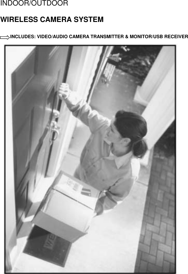
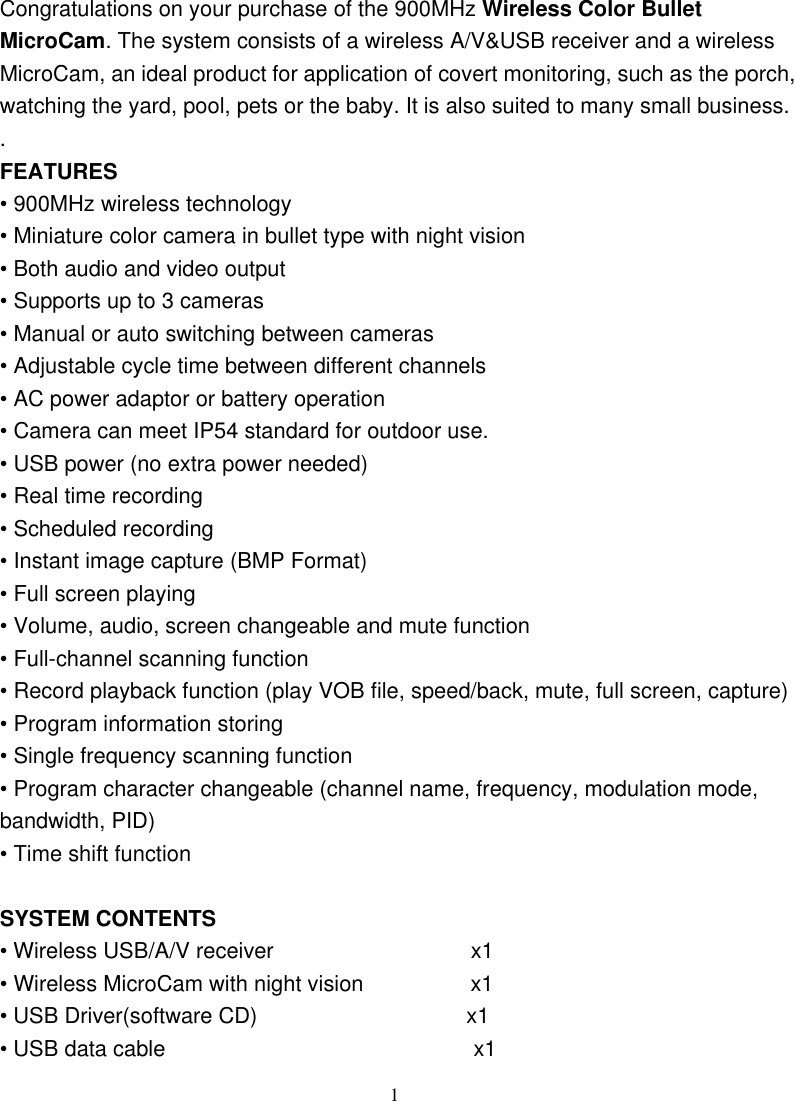
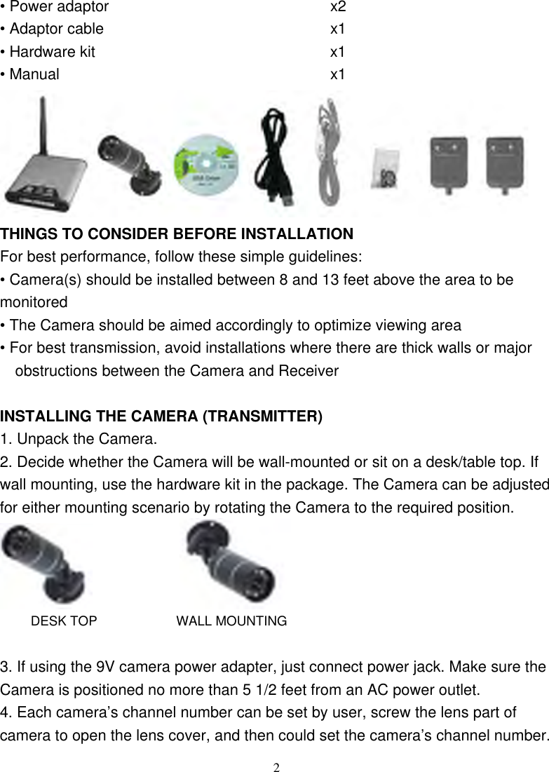
RDI Technology (Shenzhen) Co., Ltd. WIRELESS CAMERA SETTING UP THE RECEIVER

USERS MANUAL

INDOOR/OUTDOOR WIRELESS CAMERA SYSTEM USINCLUDES: VIDEO/AUDIO CAMERA TRANSMITTER & MONITOR/USB RECEIVER                         CR1122  USER’S GUIDE
 1Congratulations on your purchase of the 900MHz Wireless Color Bullet MicroCam. The system consists of a wireless A/V&USB receiver and a wireless MicroCam, an ideal product for application of covert monitoring, such as the porch, watching the yard, pool, pets or the baby. It is also suited to many small business.. FEATURES • 900MHz wireless technology • Miniature color camera in bullet type with night vision • Both audio and video output • Supports up to 3 cameras • Manual or auto switching between cameras • Adjustable cycle time between different channels • AC power adaptor or battery operation • Camera can meet IP54 standard for outdoor use.   • USB power (no extra power needed)   • Real time recording   • Scheduled recording   • Instant image capture (BMP Format)   • Full screen playing   • Volume, audio, screen changeable and mute function   • Full-channel scanning function   • Record playback function (play VOB file, speed/back, mute, full screen, capture) • Program information storing   • Single frequency scanning function   • Program character changeable (channel name, frequency, modulation mode, bandwidth, PID)   • Time shift function    SYSTEM CONTENTS • Wireless USB/A/V receiver               x1 • Wireless MicroCam with night vision         x1 • USB Driver(software CD)                   x1 • USB data cable                            x1
• Power adaptor                       x2 • Adaptor cable                       x1 • Hardware kit                     x1 • Manual                          x1  THINGS TO CONSIDER BEFORE INSTALLATION For best performance, follow these simple guidelines: • Camera(s) should be installed between 8 and 13 feet above the area to be monitored • The Camera should be aimed accordingly to optimize viewing area • For best transmission, avoid installations where there are thick walls or major obstructions between the Camera and Receiver  INSTALLING THE CAMERA (TRANSMITTER) 1. Unpack the Camera. 2. Decide whether the Camera will be wall-mounted or sit on a desk/table top. If wall mounting, use the hardware kit in the package. The Camera can be adjusted for either mounting scenario by rotating the Camera to the required position.                 DESK TOP            WALL MOUNTING  3. If using the 9V camera power adapter, just connect power jack. Make sure the Camera is positioned no more than 5 1/2 feet from an AC power outlet. 4. Each camera’s channel number can be set by user, screw the lens part of camera to open the lens cover, and then could set the camera’s channel number.  2
 3After finish setting the channel, screw the lens cover on. 5. The Camera (Transmitter) installation is now complete.  Night Vision/// The Camera includes IR LEDs, which allows viewing up to 12 feet in the dark when used with the adapter. It can automatically turn to night vision in low light.  SETTING UP THE RECEIVER 1. Connect one end of the cable to the back of the receiver, the another end (RCA cord) to your television's A/V inputs, the yellow plug to the VIDEO IN jack and the white plug to the AUDIO IN jack. 2. Plug the receiver power adapter into the 9V DC power jack on the back of the receiver and plug the power adapter into any 120 V power outlet. 3. Place the receiver either on top or near to your TV. Rotate the antenna to a vertical position. 4. When just use the USB function, firstly, put the software CD into the CD-ROM and install the USB driver software into your computer, then you will see “Soho surveillance” and “AMCAP W” on your computer table. Secondly, open the “Soho surveillance” and then connect the USB cable to the computer( there is no extra power needed), now you can control the receiver by computer.  OPTIMIZING THE WIRELESS CAMERA SYSTEM The 900MHz video signals pass easily through your home’s interior walls, but the signal may be reflected by power wires or plumbing inside the wall. Usually a slight adjustment of the Receiver and/or Camera antenna will improve reception. Take care not to force the antennas past their lock positions. The most common source of interference are microwave ovens. Try to avoid mounting the Receiver near WiFi wireless network or other source of RF interference such as cordless phones.  OPERATING THE SYSTEM Set your TV to monitor the VIDEO INPUT designated for the Receiver. The receiver can support up to three different camera/transmitter signals. You can
 4switch from one camera to the next either manually or automatically via button on the top panel of the receiver.  MANUAL MODE To select one of the three channels manually, press the MANUAL button on the panel of the receiver.   The receiver will switch to a different channel (CAM1, CAM2) each time when the MANUAL button is pressed. To avoid searching channels that do not have cameras/transmitters assigned to them, set the DIP switches (located on the rear panel of the receiver) for those corresponding channels to the OFF position (up). When you have selected a channel with an active camera, that video will appear on your TV screen    AUTO MODE To have the receiver automatically rotate through the channels, press the AUTO button on the top panel of the receiver. The receiver will continuously scan through all channels which are ON. To avoid searching channels that do not have cameras/transmitters assigned to them, set the DIP switches for those corresponding channels to the OFF position. The monitor will display the picture from one camera to the next, while the beeper will sound. The dwell time (time taken to switch between cameras) is preset to 4 seconds and can be adjusted between 2-30 seconds. To adjust the dwell time, press both the AUTO and MANUAL button simultaneously. Each flash of the LED increases the dwell time by one second.  TROUBLE SHOOTING If you are having trouble operating this product, please consult the guide below: SYMPTOM REMEDIES No camera picture 1. Check all connectors. Make sure camera(s) and receiver are switched ON. 2. Ensure camera(s) and receiver are set to correct
 channel(s). 3. Make sure camera is within range of receiver.   Blank monitor 1. Make sure receiver is switched ON. 2. If using AC adapter, make sure it is plugged in.      Interference on camera picture 1. Make sure each camera (transmitter) is within range, and that no large obstructions are blocking the signal. 2. Try repositioning the camera, receiver or both to improve the reception quality. 3. If a camera is positioned close to the receiver, point antenna away from the receiver. 4. Reposition other nearby equipment transmitting on 900MHz frequency    Audio problems 1. Ensure the volume is turned up sufficiently on the TV.2. Make sure the sound is within the microphone range. 3. If the unit emits a loud wailing sound (feeds back), try moving the camera away from the receiver or angle the receiver differently.    Camera SPECIFICATIONS TV System  PAL or NTSC Resolution  360 horizontal TV Lines Signal/Noise Ratio  48dB High-Speed Electronic Shutter  1/60 - 1/15,000 sec Image Sensor  1/3” CMOS Min. Illumination  0.5 lux Current Consumption  160mA Overall Size  3.25”Lx1.2”Diameter (antenna not included) Frequency Range  900-930MHz Modulation FM Video Signal/Noise Ratio  48dB  5 910, 920MHz
                       APPROVALS///   This device complies with part 15 of the FCC rules. Operation is subject to the following two conditions: (1) this device may not cause harmful interference, and (2) this device must accept any interference received, including interference that may cause undesired operation.  FCC NOTE: The manufacturer is not responsible for any radio or TV interference caused by unauthorized modifications to this equipment. Such modifications could void the user's authority to operate the equipment   WARRANTY/// This product has a one year manufacturer’s warranty which covers parts and labor only. In the Unlikely event that you encounter a problem, the unit should be returned to the place of purchase   Drilling Template for Wall Mounting Camera(s)/// For  wall-mounting  Camera  (s),  drill  three  holes  using  a  1/4”  drill  bit   and   the template below. Insert supplied wall anchors into holes and secure Camera to wall with supplied screws.        6 910,920MHz
                   DRILL HOLES IN THIS TWO POSITIONDRILL HOLE IN THIS  POSITION                   7

Navigation menu