RDI Technology CA190 Wireless Camera User Manual
RDI Technology (Shenzhen) Co., Ltd. Wireless Camera
Users Manual
900 MHz WIRELESS COLOR CAMERA SYSTEM
US INCLUDES: VIDEO/AUDIO CAMERA & RECEIVER
CR1916-9 USER’S GUIDE
1
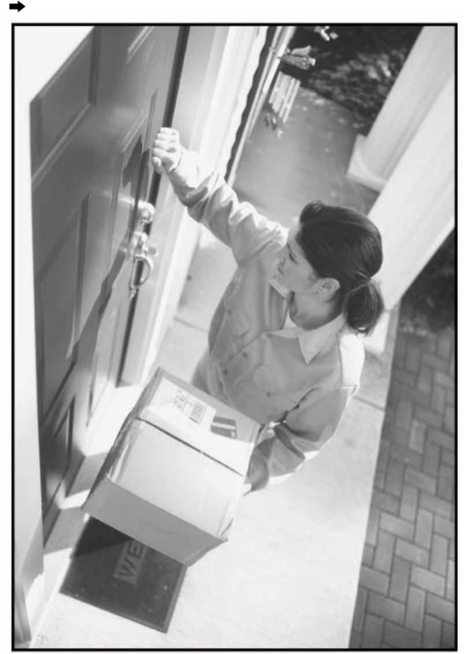
Congratulations on your purchase of the 900 MHz Wireless Color Camera System. The system
consists of a wireless color camera with night vision and an A/V receiver, which is an ideal product
for application of monitoring the porch, the yard, the pool, the pets and the baby. It is also suited to
small business surveillance application.
FEATURES
• 900MHz wireless technology with WiFi interference free
• Each system supports 2 cameras
• Color camera with good night vision
• Camera can be desktop stand or wall mounted
• Manual or auto switching between cameras
• Adjustable cycle time between different channels
• Sun shield for camera outdoor use
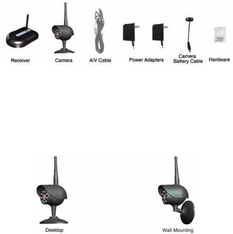
SYSTEM CONTENTS
• Wireless A/V Receiver x1
• Wireless Color Camera x1
• Power Adaptor x2
• A/V Cable x1
• Camera Battery Cable x1
• Hardware Kit x1
• Manual x1
THINGS TO CONSIDER BEFORE INSTALLATION
For best performance, follow these simple guidelines:
• Camera(s) should be installed between 8 and 13 feet away from the area to be monitored
• Camera(s) should be aimed accordingly to optimize viewing area
• For best transmission, avoid installations where there are thick walls or major obstructions between
the camera and receiver
INSTALLING THE CAMERA
1. Unpack the camera.
2
2. Decide whether the camera will be wall mounted or sit on a tabletop. If on a tabletop, install it as it
is. If wall mounted, loosen the screw on the bracket and pull the camera out of the base bracket.
Then insert the camera to the other hole in the base bracket (as shown in above pictures), then tight
the screw. Use the hardware kit in the package and drill template to mount the base bracket onto the
wall. The camera can be adjusted by rotating the camera to required position.
3. Plug the power adapter for the camera to a power outlet and connect the other end to the camera.
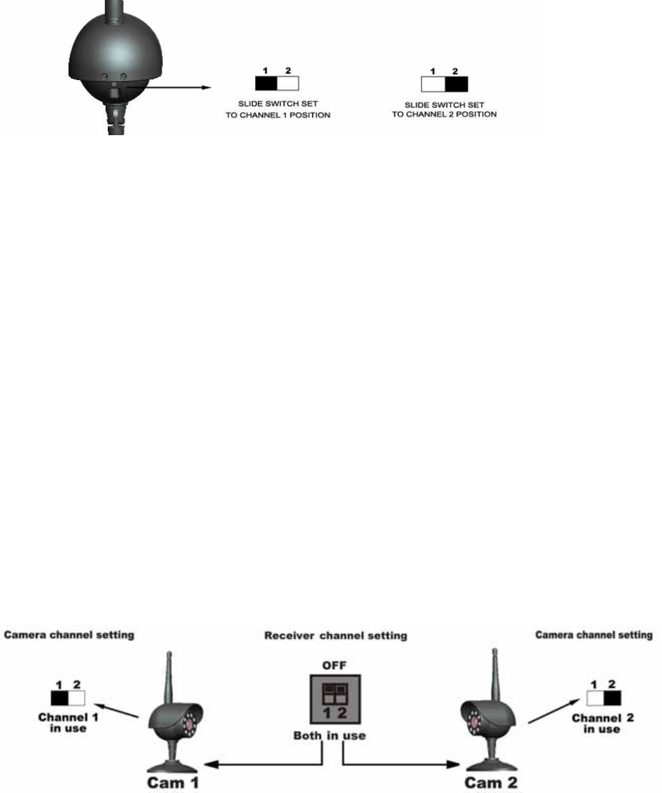
4. Each camera’s channel can be set by users. Move the slide switch to position 1 or 2 to set the
camera channel
The camera installation is completed.
Night Vision///
The camera includes 8 IR LEDs, which allows viewing more than 20 feet in the dark when used with
the power adapter. It can automatically turn to night vision mode in low light.
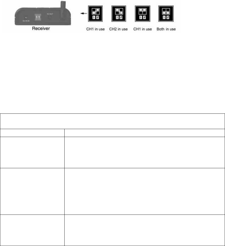
SETTING UP THE RECEIVER
1. Connect the A/V cable to the back of the receiver, the other end (RCA cord) to the A/V inputs of a
TV or other viewing and recording devices, the yellow plug to the ‘VIDEO IN’ jack and the white
plug to the ‘AUDIO IN’ jack.
2. Plug the power adapter for the receiver to a power outlet and connect the other end to the
receiver.
3. Rotate the antenna to vertical position.
The receiver installation is completed.
OPTIMIZING THE WIRELESS CAMERA SYSTEM
The 900MHz video signals can pass easily through your home’s interior walls. And usually a slight
adjustment of the receiver antenna can improve the signal reception. Take care not to force the
antenna past their lock positions.
TWO CAMERAS OPERATION
This 900MHz Wireless Color Camera System can support 2 cameras. Additional camera is sold
separately. When using 2 cameras, please set the 2 cameras to different channels, accordingly the
two dip switches located on the back of the receiver should be both switched on.
3
OPERATING THE SYSTEM
The system supports two cameras. Users can switch from one camera to the other one manually or
automatically by pressing the buttons on the top panel of the receiver. Be sure that the both dip
switches in the receiver should be switched on.
MANUAL MODE///
To select one of the two channels manually, press the MANUAL button on the top panel of the
receiver. The receiver will switch to a different channel (CAM1, CAM2) each time when the MANUAL
button is pressed. When you select a channel with an activated camera, the video will appear on TV
screen.
AUTO MODE///
To have the receiver automatically switch between the 2 channels, press the AUTO button on the top
panel of the receiver. The receiver will continuously scan through both channels which are on. The
TV screen will display the picture from one camera to the other. The dwell time (time taken to switch
between cameras) is preset to 4 seconds and can be adjusted between 2-30 seconds. To adjust the
dwell time, press both the AUTO and MANUAL button simultaneously. Each sound of the receiver
increases the dwell time by one second. And the dwell time equals to the number of sound added to
one second.
TROUBLE SHOOTING
If you have trouble operating this product, please consult the guide below:
SYMPTOM REMEDIES
No camera picture
1. Check all connections. Make sure the adapter is plugged in.
Camera(s) and receiver should be switched ON.
2. Ensure camera(s) and receiver are set to correct channel(s).
3. Make sure camera is within range of receiver.
Interference on camera
picture
1. Make sure each camera is within range, and that no large
obstructions are blocking the signal.
2. Try repositioning the camera, receiver or both to improve the
reception quality.
3. If a camera is positioned close to the receiver, point antenna
away from the receiver.
Audio problems
1. Ensure the volume is turned up sufficiently on the TV.
2. Make sure the sound is within the microphone range.
3. If the unit emits a loud wailing sound (feeds back), try moving
the camera away from the receiver or angle the receiver differently.

4
SPECIFICATIONS
Camera
TV System NTSC
Integrated Lens 5.6mm, F2.0 fixed focus
Resolution 360 horizontal TV Lines
High-Speed Electronic Shutter 1/60 - 1/15,000 sec
Image Sensor 1/4” CMOS
Min. Illumination 0.1 lux
Current Consumption Approx. 160mA with IR lights on
Overall Size 1.4"Dia x 2.5”H (excluding antenna length)
Frequency 910MHz and 920MHz
Modulation FM
Signal/Noise Ratio 48dB
Case Finish ABS Plastic
Receiver
Frequency 910MHz and 920MH
Signal/Noise Ratio 48dB
Operating Temperature -10oC to +40oC
Output Audio/Video
Humidity Less than 85%
Current Consumption Approx. 100 mA
Overall Size 3.25” W x 1.0” H x 5.0” D
Approvals
This device complies with part 15 of the FCC rules. Operation is subject to the following two
conditions: (1) this device may not cause harmful interference, and
(2) this device must accept any interference received, including interference that may cause
undesired operation.
FCC NOTE
The manufacture is not responsible for any radio or TV interference caused by unauthorized
modifications to this equipment. Such modifications could void the user's authority to
opereate the equipment.
WARRANTY
This product has a one year manufacturer’s warranty which covers parts and labor only. In the
Unlikely event that you encounter a problem, the unit should be returned to the place of purchase.
5
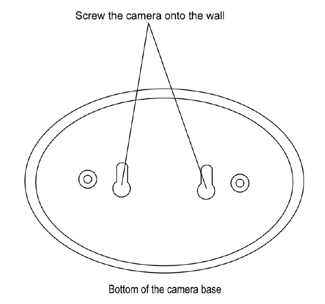
Drilling Template for Wall Mounting Camera(s)
For wall-mounting Camera (s), drill two holes using a 1/4” drill bit and the template below. Insert
supplied wall anchors into holes and secure Camera to wall with supplied screws.