RDI Technology CA670C DIGITAL WIRELESS CAMERA User Manual CA670C Manual
RDI Technology (Shenzhen) Co., Ltd. DIGITAL WIRELESS CAMERA CA670C Manual
USERS MANUAL
DIGITAL WIRELESS CAMERA
INSTRUCTION MANUAL
MODEL: CA670
1
Features
• Digital wireless technology provides excellent image quality and clarity
• Interference free, secure and private signal
• Up to 300ft wireless transmission range ①
• VGA resolution camera
• Night vision allows for low light viewing up to 40 feet / 12 meters
• Built-in microphone
• Weatherproof for outdoor use
• PIR Sensor for motion detection
① IR illumination range of 40ft./12m under ideal conditions. Objects at or beyond this range may be
partially or completely obscured, depending on the camera application.
Overviews
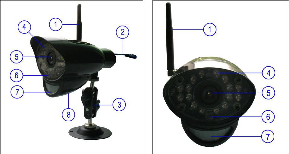
Front & Side Controls
1. Camera Antenna – Sends & receives signals to or from the receiver.
2. AC Adaptor Jack – Plug the AC adaptor to the jack for camera’s power supply.
3. Wall Mounting Bracket – Use the bracket to mount the camera on a wall or other flat surfaces.
4. IR LEDs – Infrared LEDs provide viewing in no/low light conditions
5. Lens – Catches the video in front of the lens and transmits video from camera to receiver.
6. Microphone – Receives sounds from the area near the camera, and transmits sound from the
camera to the receiver.
7. PIR Sensor – Detects motion in front of the lens and emits detection signal to transmitter.
2
8. Speaker – Produces the sound transmitted from the receiver.
Back Controls
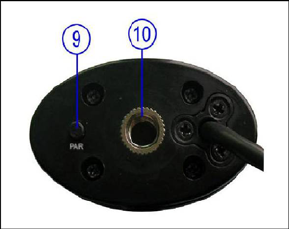
9. Pair Button – The pair button is located on the back of the camera,
it is used to pair the camera with receiver.
10. Bracket Jack – Screw the wall mounting bracket to the jack, and
fix the bracket on a wall or other flat surfaces.
Camera Installation
Before you install the camera, carefully plan where and how it will be positioned, and where you will
route the cable that connects the camera to the power adaptor.
Before starting permanent installation, verify its performance by observing the image on the receiver
when camera is positioned in the same location/position where it will be permanently installed and the
receiver is placed in the location where it will be used most of the time.
Installation Warnings
Aim the camera(s) to best optimize the viewing area: Select a location for the camera that provides a
clear view of the area you want to receive, which is free from dust, and is not in line-of-sight to a strong
light source or direct sunlight.
Avoid installing the cameras where there are thick walls, or obstructions between the cameras and the
receiver.
Night Vision
This camera has built-in IR LEDs, which provides the camera with the ability to view images in no/low
light conditions. Night vision will be automatically switched on in low illumination condition.
Installing the Camera
1. Carefully unpack the camera.
NOTE: If you are installing cameras that did not come with the system, please see the pairing camera
section of this manual for installation details.
2. Mount the camera to the wall.
Mark the position of the screw holes on the wall, drill holes and insert the supplied 3 plastic anchors, then
firmly fix the camera bracket to the plastic anchors with supplied screws.
3. Adjust the viewing angle of the camera
You can adjust the viewing angle to monitor desired area by rotating the camera bracket.
4. Connect camera power
After the camera is installed, plug the AC adaptor power output cable into the 9V POWER jack of the
camera, and plug the power plug into a wall outlet or surge protector.
NOTE: You can install additional cameras (maximum of 4 cameras). When adding cameras that were
3
not included in the original box, you will need to pair the cameras with the receiver. Refer to the camera
pairing section of this manual.
Camera installation is now completed.
Camera Pairing
The system comes with camera(s) that have already been paired. These cameras will communicate with
the receiver once powered on.
The pairing function assigns each camera to a different channel on the wireless receiver (up to 4
cameras), and is necessary for configuring additional cameras.
NOTE: It is highly recommended to pair the cameras to the receiver before permanently mounting the
cameras.
1. Power on the receiver by connecting it to power outlet with supplied 5V power adaptor.
2. Power on the camera by connecting it to power outlet with supplied 9V power adaptor.
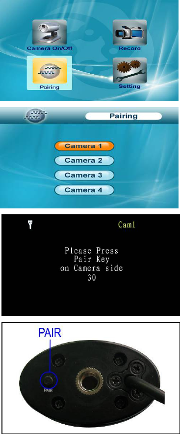
3. Press the Menu button on the receiver or remote controller.
Navigate to the Pairing menu option by pressing the ▼▲◄►
buttons on the remote controller or operating the joystick on the
receiver. Press the Enter button to enter the pairing operation.
4. Select a channel by pressing the UP and DOWN ▼▲ buttons
on the remote controller or pushing upwards/downwards the
joystick on the receiver. Press the Enter button to confirm the
selection.
5. A message will be displayed on the receiver screen.
The receiver will count down from 30~0 – you must press the
Pair button on the camera during this time to successfully pair
the camera.
If the button on the camera is not pressed, the receiver will
return to the view screen, and no pairing will take place.
6. Press the Pair button on the back of the camera.
Once the camera has been paired, it will be immediately
viewable on the receiver monitor.

4
Troubleshooting
If you have problems with the system, there is often a quick and simple solution. Please try the following:
Problem Solution
No picture from a camera
1. Check all connections to the camera. Make sure the adaptor is
plugged in.
2. Make sure that the receiver is ON.
3. Make sure that the camera is in range of the receiver.
The picture is dropping
1. Move the camera closer to the receiver.
2. Try repositioning the camera, receiver or both to improve the
reception.
Audio problems
1. Increase the volume when there is no sound.
2. Make sure that there is sound within range of the camera
microphone.
3. If the unit emits a loud screeching noise (audio feedback), move
the camera or receiver farther apart.
The picture is or has become
choppy
The picture may become choppy when experiencing a lower frame
rate (i.e. 10 frames per second vs. a higher 20 frames per second).
Try moving the camera closer to the receiver. Remove obstructions
between the receiver and camera.
The Picture appears to be grainy
when using AV out function to
view on a large screen TV/Monitor
The purpose of the AV output is for convenience only. When using
with large screen TV/Monitor, the picture might be grainy as the
camera limits video resolution to VGA (640x480 pixels). This is not a
product defect.
1. For best performance use with TV/Monitor PIP (Picture in Picture)
function. Check your TV/Monitor product manual to see if this feature
is available on your TV/Monitor.
2. View video on a smaller screen TV/Monitor.
Recording Problems
1. Make sure the SD card is inserted to SD card slot correctly.
2. Check the SD card is not full of memory.
3. Make sure the size of SD card is compatible with the system. The
system can support up to 16GB SD card.

5
Appendix #1 – System General Specifications
Operating Frequency Range 2.400GHz~2.483GHz
TX Power 14dBm
RX Sensitivity -81dBm
Type of Spread Spectrum Used FHSS
Type of Modulation Used GFSK
Data Rate 2Mbps
Communication Range 100m Line of Sight
Appendix #2 - Camera Specifications
Camera(s)
Image Sensor Type 1/4" Color CMOS Image Sensor
Effective Pixel H: 640, V: X: 480,
Image Resolution H: 640, V: 480 @ 9fps. H:320, V: 240 @25fps
Lens 4.5mm F 2.0
AGC Auto
AES Speed 1/60~1/15,000 Sec
White Balance Auto
Power Requirement 9V DC +/-10%.
Power Consumption Max 350mA with IR LED, Max 145mA without IR LED.
Operating Temp Range -10~50 degree C
Operating Humidity Range Within 85%RH
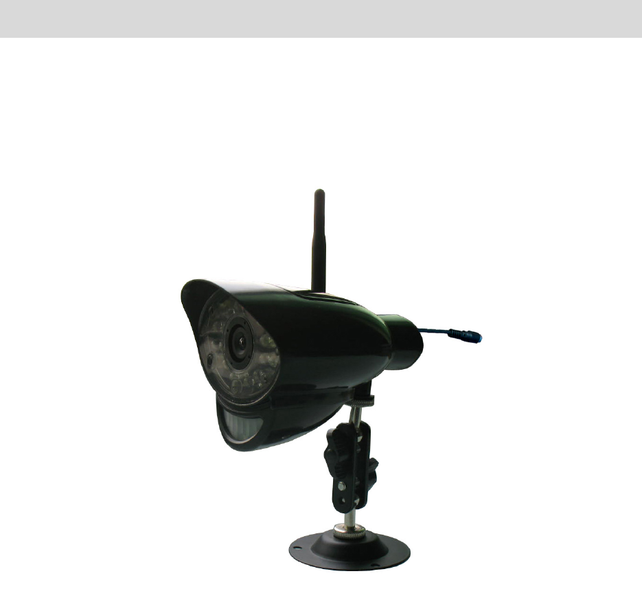
Dimension 115mm x 72mm x 70mm
Environment Rating IP54
Regulation Compliance FCC/IC
RoHS Compliance Yes
Camera Housing Material ABS Plastic
FCC NOTE:
This equipment has been tested and found to comply with the limits for a Class B digital
device, pursuant to Part 15 of the FCC Rules. These limits are designed to provide reasonable
protection against harmful interference in a residential installation. This equipment generates,
uses and can radiate radio frequency energy and, if not installed and used in accordance with
the instructions, may cause harmful interference to radio communications. However, there is
no guarantee that interference will not occur in a particular installation. If this equipment does
cause harmful interference to radio or television reception, which can be determined by
turning the equipment off and on, the user is encouraged to try to correct the interference by
one or more of the following measures:
-- Reorient or relocate the receiving antenna
-- Increase the separation between the equipment and receiver.
-- Connect the equipment into an outlet on a circuit different
from that to which the receiver is connected.
-- Consult the dealer or an experienced radio/TV technician for help.
This device complies with Part 15 of the FCC Rules. Operation is subject to the following two
conditions: (1) this device may not cause harmful interference, and (2) this device must accept
any interference received, including interference that may cause undesired operation.
The manufacturer is not responsible for any radio or TV interference caused by unauthorized
modifications to this equipment. Such modifications could void the user's authority to operate
the equipment.
The antenna used for this transmitter must be installed to provide a separation distance of at least
20 cm from all persons and must not be co-located or operated in conjunction with any other
antenna or transmitter
IC NOTE:
This device complies with Industry Canada licence-exampt RSS standard(s):Operation is
subject to the following two conditions: (1) this device may not cause interference, and (2)
this device must accept any interference, including interference that may cause undesired
operation of the device."
This Class [B] digital apparatus complies with Canadian ICES-003.